manuals.online logo
Brands
  1. Home
  2. •
  3. Brands
  4. •
  5. Ekinex
  6. •
  7. Gateway
  8. •
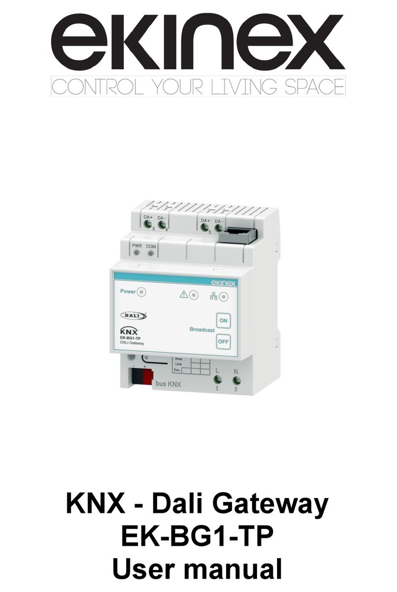
  9. Ekinex EK-BG1-TP User manual

Ekinex EK-BG1-TP User manual

1
Description
The ekinex EK-BG1-TP gateway establishes the bidirec-
tional data connection between a DALI system and a KNX
bus system. The gateway allows you to control lighting
devices equipped with a standard DALI interface and
di󰀨erent light sources (such as uorescent lamps, high
intensity discharge lamps and LEDs) by means of KNX
devices (such as buttons, motion and presence sensors
or touchpanels). The device has an integrated KNX bus
communication module and is designed for mounting on a
35 mm profile DIN rail. The device is powered at 230 VAC
and supplies SELV power to the DALI bus.
DALI
DALI (Digital Addressable Lighting Interface) is an open
and interoperable worldwide standard dedicated to ligh-
ting applications and specified by the IEC (International
Electrotechnical Commission). The DALI protocol is inclu-
ded in the technical standard IEC 62386 Digital addressa-
ble lighting interface.
For further information: www.dali-ag.org.
Main features
• Plastic case
• Version for mounting on 35 mm profile DIN rail (accor-
ding to EN 60715)
• Degree of protection IP20 (according to EN 60529)
• Security class II
• Weight 200 g
• 4 UM modular device (1 UM = 18 mm)
• Dimensions 72 x 95 x 60 mm (LxHxP)
Datasheet STEKBG1TP_EN
Technical data:
Connections:
• Power supply (230 V AC)
• KNX bus
• DALI bus
• Ethernet
DALI System:
• Transmission medium: unshielded cable
• Topology: linear, star or mixed
• Current consumption: max 250 mA
• DALI voltage: 9.5 V ... 22.5 V (typical 16 V)
• Max cable length: 300 m (section 1.5 mm²)
• Baud rate: 1200 bps
• Max number of DALI devices: 64
• Max number of DALI groups: 16
• Max number of DALI scenes: 16
Environmental conditions:
• Temperature range: -5 ... + 45°C
• Relative humidity: 95% non condensing
Operating, signaling and connecting elements
The appliance is equipped with:
• One terminal for the KNX bus line connection (1)
• Two terminals for the power supply connection (4)
• Two 2-pole terminals for the DALI bus connection(5)
• One RJ45 connector (6)
• One KNX programming button (2) with associated LED
(3)
• Three signaling LEDs (9, 10, 11)
• Two membrane keys (12)
KNX - Dali Gateway
Code: EK-BG1-TP
Mounting
The device has degree of protection IP20 and is there-
fore suitable for use in dry indoor environments. The en-
closure is designed to be mounted on a DIN profile rail
according to EN 60715 inside switchboards or electrical
distribution cabinets. The device must be mounted in a
vertical position; correct positioning is with the terminal for
the KNX bus is located at the bottom.
i
Note. When installing in switchboards and distribution cabinets,
the necessary ventilation must be ensured in order to maintain
the temperature within the operating range allowed for the ap-
pliance.
11
4
6
10
12
3
9
8
7
5
12
2
Connections
Electrical power supply
!
!
Warning! The electrical connection of the device can be carried
out only by qualied personnel. The incorrect installation may
result in electric shock or re. Before making the electrical con-
nections, make sure the power supply has been turned off.
The connection to the power supply takes place via the
screw terminals located on the front of the appliance at
the bottom.
Terminal characteristics:
• Screw tightening of conductors
• Max section of conductors 2,5 mm²
• Wire stripping recommended approx. 6 mm
• Max torque 0.5 Nm
Bus KNX
Warning! In order to supply the KNX bus lines use only KNX bus
power supplies (e.g. ekinex EK-AB1- TP or EK-AG1-TP). The
use of other power supplies can compromise the communication
and damage the devices connected to the bus.
The connection to the KNX bus line takes place via the
black / red terminal included in the supply and inserted in
the special housing located on the front of the appliance
at the bottom.
Characteristics of the KNX terminal:
• Spring tightening of conductors
• 4 conductor seats for each polarity
• Suitable for KNX bus cable with single-wire conductors
with a diameter between 0.6 and 0.8 mm
• Recommended wire stripping approx. 5 mm
• Color coding: red = bus conductor + (positive), black =
bus conductor - (negative)
DALI Bus
The connection to the DALI bus takes place via the screw
terminals located on the front of the device on the top
side. For convenience there are two pairs of terminals:
the bus can be connected indi󰀨erently to one or the other
pair. The remaining pair can be used for support or for
other purposes (measurement etc.)
Characteristics of the DALI terminals:
• Screw tightening of conductors
• Max section of conductors 2,5 mm²
• Wire stripping recommended approx. 6 mm
• Max torque 0.5 Nm
Ethernet Port
The Ethernet port is used to program the device and for
communication with a LAN network.
The Ethernet connection must be made with a cable of
at least category 5E using the appropriate connector (10)
located on the top side of the device. The maximum cable
length should not exceed 100 m. The cable must comply
with T568 standards for category 5 connections up to 100
Mbps.
Configuration and commissioning
For the configuration of the device, the standard KNX
ETS application (v. 5.6.x or higher) must be installed on
the PC; throgh ETS, you can define the type and beha-
vior of the KNX communication objects that the device
exposes.
It is also necessary to install the CGEKBG1TP software
on the PC, which allows you to:
• configure the DALI system and define its parameters
• set the DALI devices (groups, scenes, IDs, etc.)
• test the communication on the DALI bus
• update the device
The software applications and files can be freelydownloa-
ded from the website www.ekinex.com; their operation is
described in the application manual. The software works
i
with Microsoft Windows (7 and following).
Note. The operation of the CGEKBG1TP conguration software
may require the installation of .NET Framework 4, freely downlo-
adable from the Microsoft website.
These activities must be carried out in conformance with
the building automation system project carried out by a
qualified professional. For detailed information on the
configuration options, refer to the appliance’s application
manual available on the website www.ekinex.com.
The following activities are finally required to complete the
commissioning of the appliance:
• carry out the electrical connections as indicated above;
• apply power;
• connect to an active KNX bus;
• switch the appliance operation to programming mode
by pressing the appropriate button located on the front.
In this operating mode the programming LED is on;
• download the physical address and configuration to the
device using the ETS program.
At the end of the download, the operation of the appliance
automatically returns to normal mode; in this operating
mode the programming LED is o󰀨. Now configure the
DALI system using the CGEKBG1TP software. The bus
device is programmed and ready for operation.
Markings
CE: the product complies with the Low Voltage Directive
(2014/35 / EU) and the Electromagnetic Compatibility Di-
rective (2014/30 / EU).
Maintenance
The appliance is maintenance-free. To clean it, use a dry
cloth. The use of solvents or other aggressive substances
is absolutely to be avoided.
3
!
The product described in this technical sheet at the end
of its useful life is classified as waste from electronic
equipment according to the European Directive 2012/19 /
EU (WEEE), and cannot be disposed of as unsorted mu-
nicipal solid waste.
Disposal
Warning! Incorrect disposal of the product can cause serious
damage to the environment and human health. For correct di-
sposal, inquire about the collection and treatment methods pro-
vided by the local authorities.
Warnings
• Assembly, electrical connection, configuration and
commissioning of the appliance may only be carried
out by qualified personnel in compliance with the ap-
plicable technical standards and laws in force in the
respective countries
• The opening of the device housing determines the im-
mediate interruption of the warranty period
• In the event of tampering, compliance with the essential
requirements of the applicable directives for which the
appliance has been certified is no longer guaranteed
• Faulty ekinex® appliances must be returned to the ma-
nufacturer at the following address: EKINEX S.p.A. Via
Novara 37, I-28010 Vaprio d’Agogna (NO)
Other useful information
This datasheet refers to the release A1.0 of the ekinex®
device EK-BG1-TP, and is available for download at www.
ekinex.com as a PDF (Portable Data Format) file.
File name Device release Update
STEKBG1TP_EN.pdf A1.0 02 / 2021
• The instruction sheet must be delivered to the end cu-
stomer together with the project documentation
• For more information on the product, you can contact
ekinex® technical support at the e-mail address: sup-
[email protected] or consult the website www.ekinex.
com
• DALI is a registered trademark of ZVEI (Zentralverband
Elektrotechnik- und Elektroindustrie e.V.
KNX® is a registered trademark of the KNX Association
cvba, Brussels.
© EKINEX S.p.A. The company reserves the right to make chan-
ges to this technical documentation without notice.

Other manuals for EK-BG1-TP

1

Other Ekinex Gateway manuals

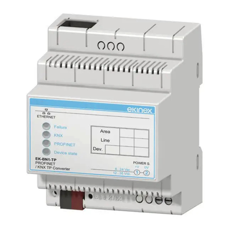
Ekinex EK-BN1-TP Instruction sheet

Ekinex

Ekinex EK-BN1-TP Instruction sheet

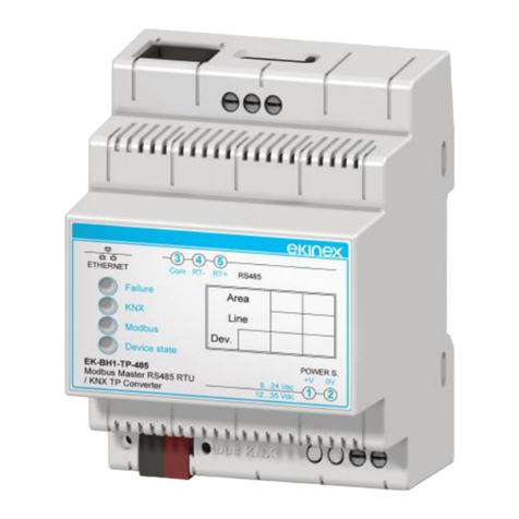
Ekinex EK-BH1-TP-485 User manual

Ekinex

Ekinex EK-BH1-TP-485 User manual

Ekinex EK-BK1-TP User manual

Ekinex

Ekinex EK-BK1-TP User manual

Ekinex EK-BF1-TP-D1 Instructions for use

Ekinex

Ekinex EK-BF1-TP-D1 Instructions for use

Ekinex EK-BG1-TP User manual

Ekinex

Ekinex EK-BG1-TP User manual

Popular Gateway manuals by other brands

OpenVox iAG801 Series user manual

OpenVox

OpenVox iAG801 Series user manual

Ultrative UTT-901 Series user manual

Ultrative

Ultrative UTT-901 Series user manual

IFM Electronic CR3146 operating instructions

IFM Electronic

IFM Electronic CR3146 operating instructions

Allied Telesis AT-iMG646PX-ON Specifications

Allied Telesis

Allied Telesis AT-iMG646PX-ON Specifications

Ihse Draco tera 480 Series Quick setup guide

Ihse

Ihse Draco tera 480 Series Quick setup guide

National Instruments WSN-9791 Getting started guide

National Instruments

National Instruments WSN-9791 Getting started guide

Spirent DX3-QSFP-DD-8 installation instructions

Spirent

Spirent DX3-QSFP-DD-8 installation instructions

Viessmann Vitogate 200 Installation and service instructions

Viessmann

Viessmann Vitogate 200 Installation and service instructions

4IPNET WHG201 user manual

4IPNET

4IPNET WHG201 user manual

RTA 460MRSBMS-NNA4 Product user guide

RTA

RTA 460MRSBMS-NNA4 Product user guide

MIKRODEV MMS100 Hardware manual

MIKRODEV

MIKRODEV MMS100 Hardware manual

Cisco Meraki Go Troubleshooting

Cisco

Cisco Meraki Go Troubleshooting

Amit IOG500AM-0T001 user manual

Amit

Amit IOG500AM-0T001 user manual

H3C MSR2600-10-X1 quick start guide

H3C

H3C MSR2600-10-X1 quick start guide

tilgin HG2700 Series quick guide

tilgin

tilgin HG2700 Series quick guide

IFM AC1401 Programming manual

IFM

IFM AC1401 Programming manual

Chipkin CAS 2700 user manual

Chipkin

Chipkin CAS 2700 user manual

Syris SY120SA-V5EM Operation manual

Syris

Syris SY120SA-V5EM Operation manual

manuals.online logo
manuals.online logoBrands
  • About & Mission
  • Contact us
  • Privacy Policy
  • Terms and Conditions

Copyright 2025 Manuals.Online. All Rights Reserved.