Ekinex EK-BA1-TP User manual

1
Line/area coupler
Product code: EK-BA1-TP
• Dimensions 36 x 90 x 70 mm (WxHxD)
Technical data
Power supply
• 30 Vdc from KNX bus line
• Current consumption (from main bus line) ca.10 mA
Environmental conditions
• Operating temperature: - 5 ... + 45°C
• Storage temperature: - 25 ... + 55°C
• Transport temperature: - 25 ... + 70°C
• Relative humidity: 95% not condensing
Switching, display and connection elements
The device is equipped with 6 LEDs, a function pushbut-
ton, 2 terminals for connecting the KNX bus lines, a pro-
gramming LED and a programming pushbutton.
KNX device with function of line/area coupler. It has to be
used in KNX installations for control of homes and buil-
dings.
Description
The ekinex®EK-BA1-TP line/area coupler allows the cou-
pling of a KNX bus main line with a KNX bus secondary
line. The device provides the galvanic isolation between
the two connected lines. Thanks to its exibility, the cou-
pler can be used as a line coupler to connect a secondary
line with a main line or as an area coupler to connect a
main line with a backbone line. The main task of the devi-
ce is ltering the trafc according to the installation place
in the hierarchy or according to the built-in lter tables
for group oriented communication. The device provides
support for long messages (up to 250 bytes) and a con-
gurable pushbutton for the activation of special functions
which are helpful during installation, run time operation
and troubleshooting. 6 LEDs accurately display the bus
status on each line. This helps identifying common com-
munication problems due to bus load or retransmissions
on both lines. The device is powered by the KNX bus line
with SELV voltage 30 Vdc and does not require any auxi-
liary power supply.
Functions
• Suppress device conguration on the sub line
• Enable or disable ltering of group messages
• Suppress device oriented messages
• Trace the trafc on the sub line
• Reduced number of retransmissions
• Auxiliary power supply not necessary
Main characteristics
• Housing in plastic material
• Mounting on 35 mm rail (according to EN 60715)
• Protection degree IP20 (according to EN 60529)
• Safety class II
• Weight 100 g
• 2 modular units (1 unit = 18 mm)
REAEKBA1TP
Switching elements
• Pushbutton (10) for switching between the normal and
programming operating mode
• Function pushbutton (4)
Long press (3 sec)
- Switch to manual overwrite, conguration is done via
ETS
- Status LED main bus line red:
On: switch on manual overwrite
Off: switch to congured routing
Very long press (15 sec)
LED: Bus Status Main (1), Bus Status Sub (7), Group
Address (3), Physical Address (9) on red. Release but-
ton and press again for some seconds: resets all the
parameter to factory default (incl. physical address).
Display elements
• Status LED main bus line (1)
- off: error
- on (green): main line ok
- on (red): manual override active
• Status LED secondary bus line (7)
- off: secondary line error or not connected
- on (green): secondary line ok
Datasheet STEKBA1TP_EN
1) Status LED main KNX bus line (green/red)
2) Trafc LED main KNX bus line (green/red)
3) Status LED lter table group addresses (green/red)
4) Function pushbutton
5) Programming LED (red)
6) Terminal block for main KNX bus line
7) Status LED secondary KNX bus line (green/red)
8) Trafc LED secondary KNX bus line (green/red)
9) Status LED lter table physical addresses (green/yellow)
10) Programming pushbutton
11) Terminal block for secondary KNX bus line
DCEKBA1TP
1
bus
status
traffic
GA
function
PA
R
EK-BA1-TP
MAIN SUB
Line/area coupler
2
3
4
5
6
7
8
9
10
11
TP1
S

2
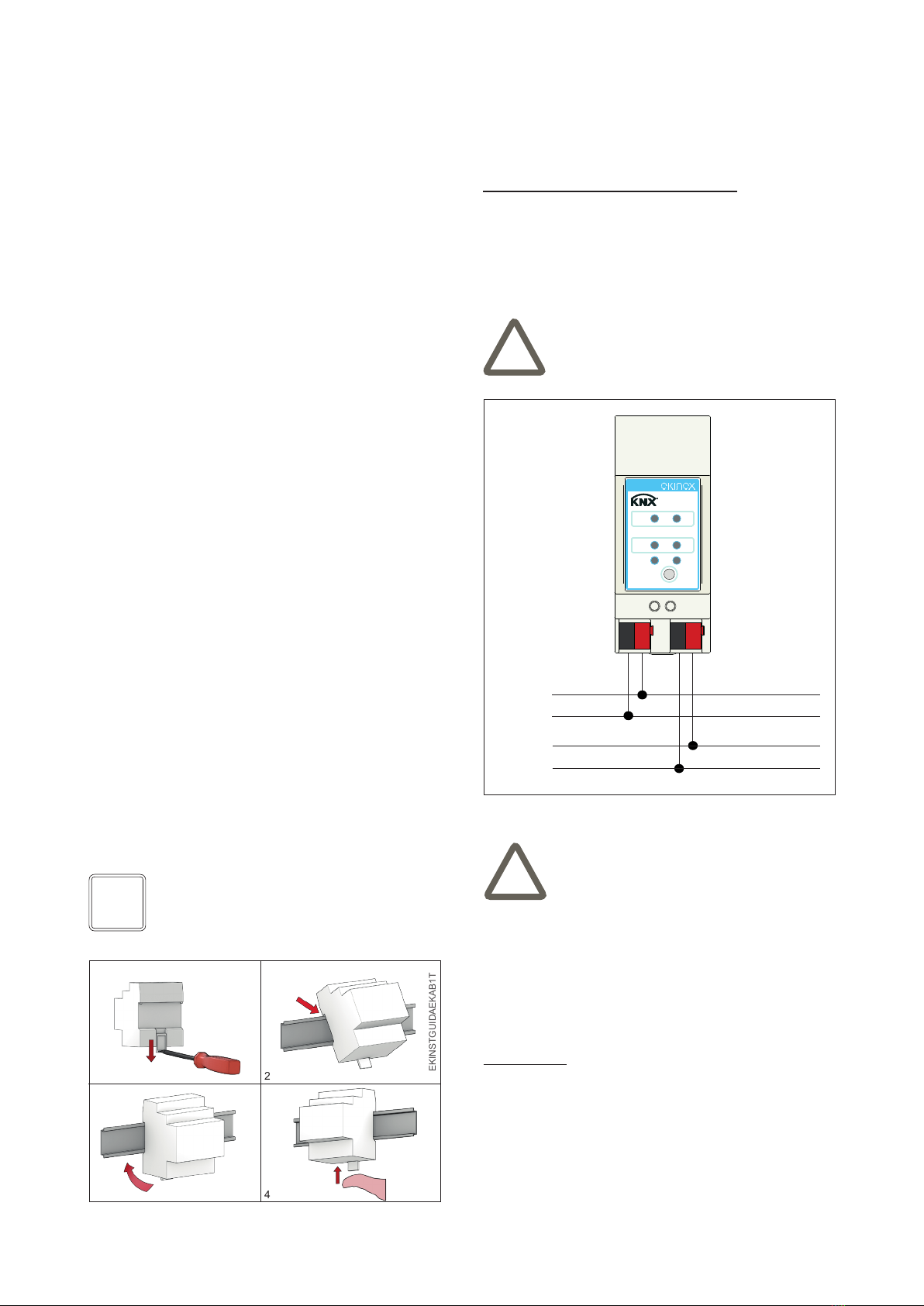
Connection of the KNX bus line
The connection to the main and secondary KNX bus lines
is made with the terminal blocks (black/red) included in
delivery and inserted into the slots located on the bottom
part of the front.
Characteristics of the KNX terminal block
• spring clamping of conductors
• 4 seats for conductors for each polarity
• terminal suitable for KNX bus cable with single-wire
conductors and diameter between 0.6 and 0.8 mm
• recommended wire stripping approx. 5 mm
• color codication: red = + (positive) bus conductor,
black = - (negative) bus conductor
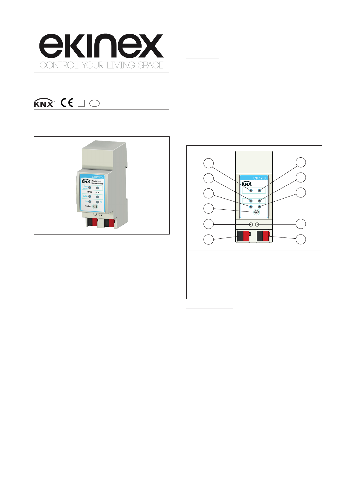
• Trafc LED main bus line (2)
- blinking (green): trafc on main bus line
- off: no trafc on main bus line
- blinking (red): transmission error
• Trafc LED secondary bus line (8)
- blinking (green): trafc on secondary bus line
- off: no trafc on secondary bus line
- blinking (red): transmission error
• Status LED group addresses (3)
Routing of group telegrams
- off: main and sub different
- on (green): lter table active
- on (green+red): route all
- on (red): block
• Status LED physical addresses (9)
Routing of physical telegrams
- off: main and sub different
- on (green): lter table active
- on (green+yellow): route all
- on (yellow): block
• LED red (5) for displaying the active operating mode
(on = programming mode, off = normal operation
mode). After receiving the physical address, the line/
area coupler automatically returns from programming
mode to the normal operating mode.
Mounting
The device has degree of protection IP20, and is there-
fore suitable for use in dry interior rooms. The housing is
made for rail mounting according to EN 60715 in boards
or cabinets for electrical distribution. The installation is in
horizontal position, the correct position is when the KNX
bus terminals are located at the bottom. For the installa-
tion of the device on the rail proceed as follows:
• with the aid of a tool bring the locking device in the fully
lowered position (1);
• place the upper edge of the rear inner prole on the
upper edge of the rail (2);
• rotate the device towards the rail (3);
• push the locking device upward until it stops (4).
Before removing the device, be sure the bus terminals
have been extracted from their slots. Use a screwdriver
to slide down the locking device and remove the device
from the rail.
Conguration and commissioning
Conguration and commissioning of the device require
the use of the ETS®(Engineering Tool Software) program
V3 or later releases. These activities must be carried out
according to the design of the building automation system
done by a qualied planner.
Conguration
For the conguration of the device parameters the corre-
sponding application program or the whole ekinex®pro-
duct database must be loaded in the ETS program. For
detailed information on conguration options, refer to the
application manual of the device available on the website
www.ekinex.com.
Note. When mounting the device in boards and ca-
binets it shall be provided the necessary ventilation
so that the temperature can be kept within the ope-
rating range of the device.
+
-
a)
Warning! The electrical connection of the device
can be carried out only by qualied personnel. The
incorrect installation may result in electric shock or
re. Before making the electrical connections, make
sure the power supply has been turned off.
bus
status
traffic
GA
function
PA
R
EK-BA1-TP
MAIN SUB
Line/area coupler
+
-
b)
a) Main KNX bus line
b) Secondary knx bus line
DCEKBA1TP
Warning! In order to supply the KNX bus lines use
only a KNX bus power supply (e.g. ekinex EK-AB1-
TP or EK-AG1-TP). The use of other power supplies
can compromise the communication and damage
the devices connected to the bus.
1 2
43
EKINSTGUIDAEKAB1TP
i!
!

3
Documentation
This datasheet refers to the release A1.0 of the ekinex®
device EK-BA1-TP, and is available for download at www.
ekinex.com as a PDF (Portable Data Format) le.
Warnings
• Installation, electrical connection, conguration and
commissioning of the device can only be carried out by
qualied personnel in compliance with the applicable
technical standards and laws of the respective countri-
es
• Opening the housing of the device causes the imme-
diate end of the warranty period
• In case of tampering, the compliance with the essential
requirements of the applicable directives, for which the
device has been certied, is no longer guaranteed
• ekinex®KNX defective devices must be returned to the
manufacturer at the following address: EKINEX S.p.A.
Via Novara 37, I-28010 Vaprio d’Agogna (NO) Italy
Other information
• This datasheet is aimed at installers, system integra-
tors and planners
• For further information on the product, please contact
the ekinex®technical support at the e-mail address:
com
• Each ekinex®device has a unique serial number on
the label. The serial number can be used by installers
or system integrators for documentation purposes and
has to be added in each communication addressed to
the EKINEX technical support in case of malfunctioning
of the device
• KNX®and ETS®are registered trademarks of KNX As-
sociation cvba, Brussels
© EKINEX S.p.A. The company reserves the right to make changes to this
documentation without notice.
Filename Device release Updating
STEKBA1TP_EN.pdf A1.0 07 / 2014
Commissioning
For commissioning the device the following activities are
required:
• make the electrical connections as described above;
• turn on the bus power supply;
• switch the device operation to the programming mode
by pressing the programming pushbutton located on
the front side of the housing. In this mode of operation,
the programming LED is turned on;
• download into the device the physical address and the
conguration with the ETS®program.
At the end of the download the operation of the device
automatically returns to normal mode; in this mode the
programming LED is turned off. Now the bus device is
programmed and ready for use
Dimensions [mm]
Product
code
Application program
(## = release)
EK-BA1-TP APEKBA1TP##.vd4
Note. The conguration and commissioning of KNX
devices require specialized skills. To acquire these
skills, you should attend the workshops at KNX cer-
tied training centers.
Marks
• KNX
• CE: the device complies with the Low Voltage Directi-
ve (2006/95/EC) and the Electromagnetic Compatibility
Directive (2004/108/EC)
Maintenance
The device is maintenance-free. To clean it use a dry
cloth. It must be avoided the use of solvents or other ag-
gressive substances.
90
36 545 20
70
bus
status
traffic
GA
function
PA
R
EK-BA1-TP
MAIN SUB
Line/area coupler
DQEKBA1TP
Disposal
At the end of its useful life the product
described in this datasheet is classied
as waste from electronic equipment in
accordance with the European Directi-
ve 2002/96/EC (RAEE), and cannot be
disposed together with the municipal
undifferentiated solid waste.
Warning! Incorrect disposal of this product may
cause serious damage to the environment and hu-
man health. Please be informed about the correct
disposal procedures for waste collecting and pro-
cessing provided by local authorities.
i
!
Other Ekinex Industrial Equipment manuals
Popular Industrial Equipment manuals by other brands

Datacolor
Datacolor AHIBA IR installation guide

Nakanishi
Nakanishi PS Series Operation manual

Eaton
Eaton Power XL SmartWire-DT DX-NET-SWD3 Instruction leaflet

IMI
IMI Bimba BPGS Series user manual

Toshiba
Toshiba WX9 ASD Installation & operation manual

Siemens
Siemens SIRIUS 3RA1913-1 Series operating instructions

SMC Networks
SMC Networks HEBC002-WA10 manual

Siemens
Siemens SIMOTICS T-1FW6 operating instructions

Gebhardt Anlagentechnik
Gebhardt Anlagentechnik BBF6 Translation of the original operating manual

UniVer
UniVer DA Series instructions

ABB
ABB HT611542 Operation manual

Voltaire
Voltaire HTC Series Installation, operation and maintenance manual