Ekinex SIGNUM KNX User manual

1
SIGNUM KNX pushbutton with touch di-
splay
Codes: EK-EV2-TP-... (Deep)
EK-EV2-TP-S-... (Surface)
Datasheet STEKEV2TP_EN
TP1
S
REFLEKEV2TPD
KNX standard “virtual” button, based on a borderless IPS
touch display, in which each button can be customized
via a dedicated app. It is possible to change some attribu-
tes of each key even after installation, such as position,
symbols and texts.
Description
The EK-EV2-TP pushbutton with touch display of the eki-
nex® SIGNUM series is a KNX device for the on / o con-
trol of utilities, the dimming of lighting devices, the control
of motorized drives or other programmable command
and control functions. The integrated temperature sensor
also allows it to be used as a temperature controller for
an environment or area. The device is intended for KNX
standard home and building automation systems, and it is
equipped with a KNX bus communication module and is
designed for wall installation on a round or square ush
mounting box, equipped with xing holes with 60 mm cen-
ter distance. The button must be completed with a plate
from the Deep or Surface series. The 2.65“, 162 x 320
pixel 262K color borderless IPS touch display with haptic
feedback can be congured to manage up to 4 buttons
per page and up to 3 total pages. Each button can be
customized via the dedicated Ekinex Tool app via BLE
(Bluetooth Low Energy) and it is possible to change some
attributes of each button even after installation, such as
symbols and text. The proximity sensor integrated into the
plate (to be ordered separately) allows the activation of
the backlight and other functions, guarantees maximum
readability when using the pushbutton and allows visual
comfort during the night. The device is powered at SELV
30 Vdc voltage by means of the KNX bus and does not
require auxiliary power supply.
Main functional characteristics
• On/o switching of single loads or groups of loads
• Dimming of lighting devices
• Control of motor drives (for roller shutters, blinds,
curtains, etc.)
• Measuring and regulation of room temperature via
integrated sensor
• Backlight activation and other functions by means of an
integrated proximity sensor
• Logic functions
• Switching to forced operation (lock)
• Recall and memorization of scenarios
• Dierent programmable functions for short press / long
press of a button
• Touch display with haptic feedback
• Programming via Bluetooth with iOS 9.1 or Android 5.1
and higher apps
• Possibility to congure up to 12 buttons arranged on 3
pages, with a dedicated page for thermostat functions
• Customizable buttons with text or icons
• Graphic display of the thermostat function that can be
enabled via voucher
• Graphical interface for controlling audio sources, which
can be enabled via voucher
• Integration with the KNX network via ekinex®Delégo
supervision system or the ekinex® EK-BW1-TP voice
assistant interface
• Front cover with proximity sensor, in the same metal
nishes as in the catalog
• Compatibility and family feeling with the Ekinex 20venti
series
REFLEKEV2TPS
Other characteristics
• Housing in plastic material
• Wall installation in ush mounting box
• Protection degree IP20 (installed device)
• Climatic 3K5 and mechanical 3M2 classication (ac-
cording to EN 50491-2)
• Pollution degree 2 (according to IEC 60664-1)
• Weight 88 g (without mounting support)
• Dimensions 77 x 83 x 37 mm (LxHxP)
Technical data
• Power supply 30 Vdc from KNX bus line
• Current consumption from bus < 37 mA
• Max. power from bus < 1.1 W
• 2.65” IPS display, 162 x 320 pixels, 262K colors with
haptic feedback
Environmental conditions
• Operating temperature: - 5 ... + 45°C
• Storage temperature: - 25 ... + 55°C
• Transport temperature: - 25 ... + 70°C
• Relative humidity: 95% not condensing

2
0,70 ÷ 1,50 m
min 0,3 m
Delivery
The metal support for wall mounting box (cod. EK-SMQ-
71-S), the xing screws and the KNX terminal block for
the connection to the power supply are delivered with the
device.
Mounting position
If the integrated sensor is used for temperature regulation,
the device has to be installed preferably on an internal
wall at a height between 0.70 and 1.5 m and at least 0.3
m far from doors. The device can not be installed close to
heat sources such as radiators or household appliances
or in position subjected to direct sunlight. If necessary, for
the regulation can be used a weighted average between
the value measured by the integrated sensor and a value
received via bus by another KNX device.
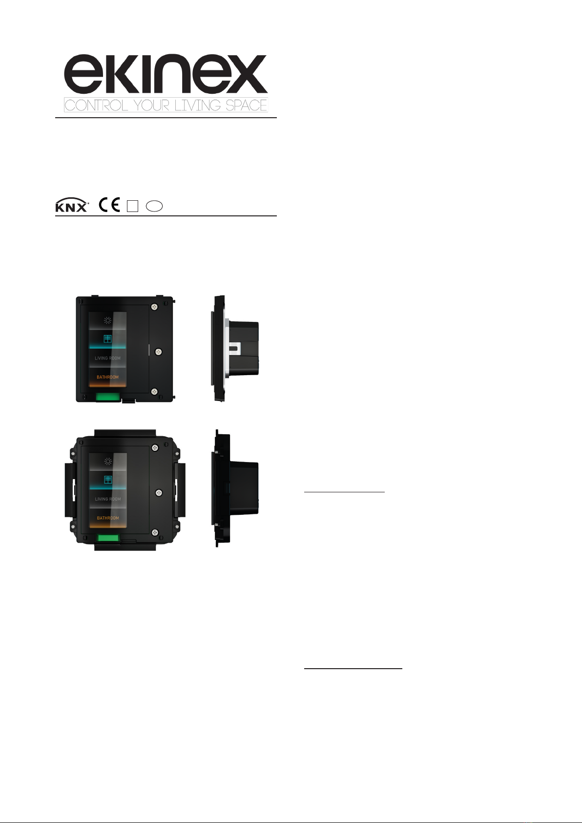
(*) To be completed with the extension for colour and nishing
SIGNUM with square single plate and
proximity sensor (*)
with 30 x 60 mm window
Code: EK-EV2-TP... (Deep version)
EK-EV2-TP-S-... (Surface version)
Mounting
The device has degree of protection IP20, and is there-
fore suitable for use in dry interior rooms. The installation
of the device can be done with round or square ush
mounting box.
To mount the device, please carry out the following ope-
rations:
Deep series
• x the metal support (e) by means of the pair of screws
(d) on the ush mounting box (g) equipped with suitable
holes;
• insert the device (b1) into the support-box assembly
(e+g), inserting the bus terminal, previously connected
to the bus cable (see: “Connection to the KNX bus
line”), in the appropriate seat on the back of the device;
• screw the device (b1) onto the support-box assembly
(e+g) using the pair of screws (c) supplied;
• mount the plate (a), by inserting it from the opposite
side to that of the proximity sensor (highlighted by the
slot) and pressing slightly in the sensor area for closure.
Surface series
• x the plastic adapter (f) by means of the pair of screws
(d) on the ush mounting box (g) equipped with suitable
holes;
• hook the device (b2), previously xed to the plate (a)
with suitable screws, to the support-box assembly (f+g)
using the magnets and inserting the bus terminal, pre-
viously connected to the bus cable (see: “Connection to
the KNX bus network “), in the special housing on the
back of the device.
Note. The plate for completing the device can be
ordered with the SIGNUM pushbutton or separa-
tely. For more information on available materials,
colours and nishes, see also the ekinex®product
catalog or browse www.ekinex.com.
i
Note. The screws supplied in the package are su-
itable for standard installations. For more specic
applications, where the screws have to be replaced,
only at-head screws must be used. The screws for
the metal support must be tightened with a max. tor-
que of 1.0 Nm.
i
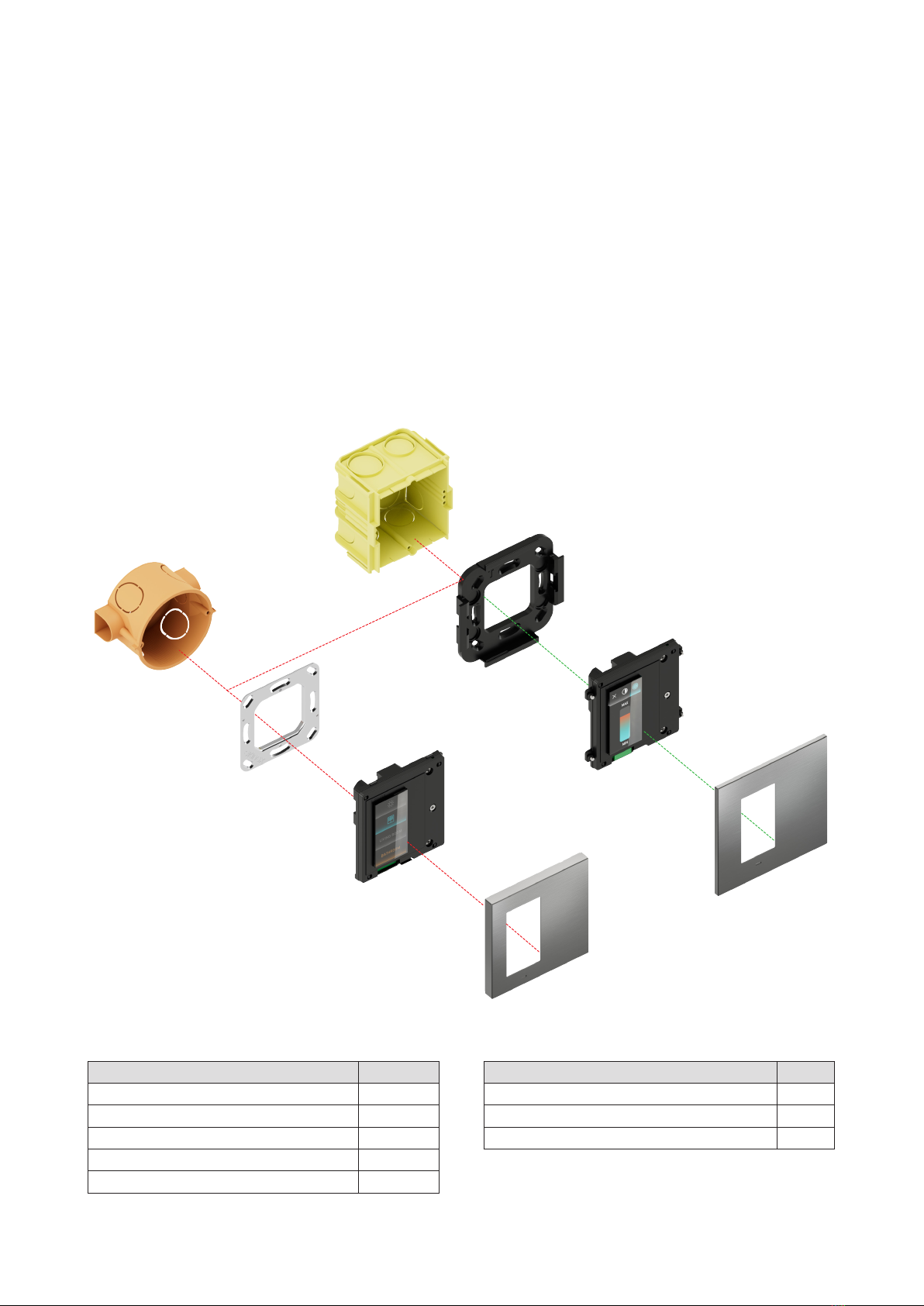
a) Deep or Surface series plate (to be ordered separately)
b1), b2) EK-EV2-TP “SIGNUM” pushbutton
c) Screws for xing the device on the support (Deep series only, in-
cluded in the delivery)
d) Fixing screws for metal support (Deep) or plastic adapter (Surface)
on wall mounting box (supplied)(included in the delivery)
e) Metal support for wall mounting box (Deep series only, included
in the delivery)
f) Adapter in plastic material with magnets for wall mounting obx (Sur-
face series only, included in the delivery)
g) Wall mounting box (not delivered by ekinex)
Installation for Deep or Surface series
b1
e
a
c
d
g
d
f
b2
Finishing plates and proximity sensor
The device has to be ordered with an ekinex®plate in
metal (aluminum) or Metal HT (chromed), with a 30 x 60
mm window and integrated proximity sensor. The plate is
available for Deep or Surface series mounting and can be
ordered either with SIGNUM or separately.
Note. The device can be mounted with the window
on the right side, by rotating both the pushbutton
and the plate by 180 °. In this case, the proximity
sensor and its slot will be located in the upper part
of the panel, instead of at the bottom.
i

3
Main functional characteristics (thermostat function)
• Temperature measurement using the integrated sensor
with the possibility of sending the value on the bus
• 2-point room temperature adjustment (ON/OFF type) or
proportional (PWM or continuous)
• Conduction modes: heating and cooling with the pos-
sibility of switching via bus or automatic based on the
congured operating logic
• Operating modes: comfort, standby, economy and buil-
ding protection with separate setpoints for heating and
cooling operation
• Automatic switching of the operating mode according to
window opening function
• Weighted average of two temperature values
• Temperature control alarm
• Valve anti-blocking function (for hydronic systems)
Display elements
IPS touch display with virtual buttons (1), with the possibi-
lity of customizing text and icons.
Switching and display elements
The device is equipped with a IPS touch display for ac-
tivating the functions of the pushbutton and a proximity
sensor integrated in the front cover for activating the bac-
klight and other programmable functions.
Switching elements
The touch display (1) can implement up to 12 buttons ar-
ranged on 3 pages, with a dedicated page for thermore-
gulation. The methods of interaction are as follows:
• touch or tap: pressing the area of a key with the nger
for at least 15ms starts an activation or deactivation
event;
• swipe: dragging the nger vertically from one side of
the display to scroll through the function pages, while
dragging it horizontally displays the settings and infor-
mation pages;
• long press: prolonged touch (settable via ETS) of an
area of the display activates the slider functions, such
as light dimming or control of motor drives.
Horizontal swipe
Scroll through the
pages of functions,
info / programming /
reset and settings
Vertical swipe
Scrolling of function
pages only
Touch / tap
Switching On / o,
sending values or
sequences, scenes
Long press
Slider activation for
dimmer, up / down,
modication of ther-
mostat setpoint
1
2
3
1) IPS touch display
2) Contacts for connecting the proximity sensor
3) Temperature sensor position (under the cover)
4) Product label
5) Terminal block for KNX bus line
6) Locking springs for metallic support
5
4
6
1
2
3
Connection of the KNX bus line
The power supply is connected via the 2-way terminal in-
cluded in the device delivery. It has to to be wired and
inserted in the appropriate housing located on the back of
the device (5), respecting the indicated polarity.
Warning! In order to supply the KNX bus lines use
only KNX bus power supplies (e.g. ekinex EK-AB1-
TP, EK-AG1-TP or EK-AM1-TP). The use of other
power supplies can compromise the communica-
tion and damage the devices connected to the bus.
!

4
Note. The conguration and commissioning of KNX
devices require specialized skills. To acquire these
skills, you should attend the workshops at KNX cer-
tied training centers.
i
Commissioning
For the commissioning of SIGNUM, the following activi-
ties are required:
• make the electrical connections as described above;
• turn on the KNX bus power supply;
• switch the device operation to the programming mode
by scrolling the display pages to the INFO page and
pressing the PROGRAM virtual button for 5s, which will
turn red;
Characteristics of the KNX terminal block
• spring clamping of conductors
• 4 seats for conductors for each polarity
• terminal suitable for KNX bus cable with single-wire
conductors and diameter between 0.6 and 0.8 mm (20-
23 AWG)
• recommended wire stripping approx. 5 mm
• color codication: red = + (positive) bus conductor,
black = - (negative) bus conductor
• Flammability rating: UL94-V0
+
-
Bus
KNX
Warning! The electrical connection of the devi-
ce can be carried out only by qualied person-
nel. The incorrect installation may result in elec-
tric shock or re. Before making the electrical
connections, make sure the power supply has
been turned o.
!
Conguration and commissioning
Conguration and commissioning of the device require
the use of the ETS®(Engineering Tool Software) program
V4 or later releases. These activities must be carried out
according to the design of the building automation system
done by a qualied planner.
Conguration
To congure the SIGNUM parameters, the corresponding
application program or the entire ekinex®product databa-
se must be loaded into the ETS®program. For detailed
information on the parameterization, pleaseconsult the
application manual of the device available on the website
www.ekinex.com.
• download the physical address and conguration into
the device using the ETS® program.
Connection to the Ekinex Tool app
The user can customize some SIGNUM functions and at-
tributes using the “Ekinex Tool” app, available for Android
and iOS systems and downloadable from the related di-
gital stores.
At the end of the download the operation of the device au-
tomatically returns to normal mode; in this mode all LEDs
work as programmed. Now SIGNUM is programmed and
ready for use.
Note. The setup procedure requires the Bluetooth
connection of the device (smartphone or tablet). If
it is deactivated, the app will ask for its activation
through the settings options.
i
The activities to be performed to connect to the app are
as follows:
• scroll to the SETTING MODE page on the SIGNUM
display; the device is now set to perform the pairing
operation via Bluetooth;
• download and install the “Ekinex Tool” app, possibly
framing the QR code with the smartphone;
• at the rst start, follow the steps of the app wizard to
add a new device, by pressing on the virtual symbol
“+”; then, by pressing on “SIGNUM”, the conguration
starts;
• End the procedure by following the steps, as described
in the Ekinex Tool app guide.
Device reset
To reset the device, scroll the display pages to the INFO
page and press the FACTORY RESET virtual button for
a few seconds, until the brightness of the page lowers
considerably.

5
Versions
Warning! The reset restores the device back to
the state of delivery from the factory. The ad-
dress and the value of the parameters set du-
ring conguration will be lost.
!
DQEKEV2TP
The display will show the start page and the reset has
been performed. At this point it is necessary to carry out
the addressing and conguration of the device again via
ETS®.
Il display visualizzerà la pagina di avvio e il reset è stato
eettuato. A questo punto è necessario eettuare nuova-
mente l’indirizzamento e la congurazione del dispositivo
mediante ETS®.
Marks
• KNX
CE: the device complies with the Low Voltage Directive
(2014/35/EU, the Electromagnetic Compatibility Directi-
Maintenance
The device is maintenance-free. To clean use a dry cloth.
It must be avoided the use of solvents or other aggressive
substances.
Disposal
At the end of its useful life the product
described in this datasheet is classied
as waste from electronic equipment in
accordance with the European Direc-
tive 2012/19/EU (WEEE recast), and
cannot be disposed together with the
municipal undierentiated solid waste.
Documentation
This datasheet refers to the release A1.0 of the ekinex®
SIGNUM pushbuttons (codes EK-EV2-TP-... and EK-
EV2-TP-S-...) and is available for download at www.eki-
nex.com as a PDF (Portable Data Format) le.
File name Device release Updating
STEKEV2TP_EN.pdf A1.0 11 / 2022
Warnings
• Installation, electrical connection, conguration and
commissioning of the device can only be carried out by
qualied personnel in compliance with the applicable
technical standards and laws of the respective countri-
es
• Opening the housing of the device causes the imme-
diate end of the warranty period
• In case of tampering, the compliance with the essential
requirements of the applicable directives, for which the
device has been certied, is no longer guaranteed
• ekinex®KNX defective devices must be returned to the
manufacturer at the following address: EKINEX S.p.A.
Via Novara 37, I-28010 Vaprio d’Agogna (NO) Italy
Other information
• This datasheet is aimed at installers, system integra-
tors and planners
• For further information on the product, please contact
the ekinex®technical support at the e-mail address:
com
• Each ekinex®device has a unique serial number on
the label. The serial number can be used by installers
or system integrators for documentation purposes and
has to be added in each communication addressed to
the EKINEX technical support in case of malfunctioning
of the device
• KNX®and ETS®are registered trademarks of KNX As-
sociation cvba, Brussels
© EKINEX S.p.A. The company reserves the right to make changes to this
documentation without notice.
ve (2014/30/EU), the RED (Radio Equipment Directive)
2014/53/UE and the RoHS 3 Directive (2015/863/EU).
Tests carried out according to EN 63044-5-1:2019, EN
63044-5-2:2019.
Code Version Mounting
EK-EV2-TP Deep
No frame
EK-EV2-TP-S Surface
Code Voucher
EK-EV2-V1-TER Voucher to enable the graphic display
of the thermostat function
EK-EV2-V1-AUD Voucher to enable the graphic display
of the audio function
Dimensions [mm]

6
Annex 1. Installation
Ekinex®SIGNUM is a “virtual” button equipped with a
KNX communication module. It is suitable for installa-
tion on a round or square wall mounting box, equipped
with xing holes with 60 mm center distance. The button
must be completed with a plate of the Deep or Surface
series. Each button is supplied with the metal support
for mounting on the ush-mounting box (code EK-SMQ-
71-S, which can also be ordered separately if necessary),
the xing screws, the desired plate and the connection
terminal to the KNX bus line.
The cover plate is supplied in the Deep or Surface ver-
sions, with at least one 30x60 mm window, in the following
nishes: metal, Metal HT (chromed) and Fenix NTM®, in
numerous color variants.
The Fenix NTM® color eect on the Surface plate is obtai-
ned by painting.
The 2.65“ borderless RGB touch IPS display, 162 x 320
pixels, 262K colors with haptic feedback can be congu-
red to manage up to 4 keys per screen and up to 3 total
pages. Each key can be customized via a dedicated app
and it is possible to change some attributes even after
installation, such as position, symbols and texts. The
button also oers the functions of graphic display of the
thermostat and control of audio sources, with activation
via voucher.
The integrated proximity sensor integrated in the plate (to
be ordered separately) allows visual comfort during the
night.
The conguration and commissioning of the devices is
carried out using the ETS®software; the related applica-
tion programs can be downloaded from the website www.
ekinex.com.
Description Code
a) Deep version SIGNUM button EK-EV2-TP-...
b) Surface version SIGNUM button EK-EV2-TP-S-...
c) Deep version square plate (30 x 60 mm window) EK-DQV-...
d) Surface version square plate (60 x 60 mm window) EK-SQV-...
e) Deep version mounting metal support EK-SMQ-71-F
Legend
a
b
c
d
e
g
h
f
Description Code
f) Surface version mounting support (included in delivery) -
g) Round ush-mounting box (not supplied by ekinex®) -
h) Square ush-mounting box (not supplied by ekinex®) -

7
Page with 1 button
The extreme exibility of SIGNUM pa-
nel allows you to arrange the buttons
for each individual screen in 3 die-
rent ways: single button, double but-
ton and quadruple button.
Annex 2. SIGNUM pages
Page with 2 buttons
Each button can be customized with
texts, symbols and colors.
Page with 4 buttons
With the buttons it is possible to con-
trol lighting devices, scenarios and
motorized drives. Holding it down
can call up graphic pages for preci-
sion control of home automation ele-
ments.
Brightness control page
The graphic slider allows for ne control of
motorized or luminescent drives in percent.
Color temperature setting page
It is possible to enable a page dedicated to con-
trolling the tone of the light emitted by a light
source, varying from a cold color to a warmer
one.
Motorisation control page
The motorisation page allows you to control mo-
torised locking elements using the up and down
buttons.

8
Audio page
The Audio page allows you to select
an audio source, change the curren-
tly playing song, and increase or de-
crease the volume.
Audio settings page
The audio settings page allows you
to control the volume level and the
treble and bass equalization.
Room thermostat page
The thermostat page allows you to
monitor the room temperature and
control the desired temperature intu-
itively.
Table of contents
Other Ekinex Industrial Equipment manuals
Popular Industrial Equipment manuals by other brands

Datacolor
Datacolor AHIBA IR installation guide

Nakanishi
Nakanishi PS Series Operation manual

Eaton
Eaton Power XL SmartWire-DT DX-NET-SWD3 Instruction leaflet

IMI
IMI Bimba BPGS Series user manual

Toshiba
Toshiba WX9 ASD Installation & operation manual

Siemens
Siemens SIRIUS 3RA1913-1 Series operating instructions

SMC Networks
SMC Networks HEBC002-WA10 manual

Siemens
Siemens SIMOTICS T-1FW6 operating instructions

Gebhardt Anlagentechnik
Gebhardt Anlagentechnik BBF6 Translation of the original operating manual

UniVer
UniVer DA Series instructions

ABB
ABB HT611542 Operation manual

Voltaire
Voltaire HTC Series Installation, operation and maintenance manual