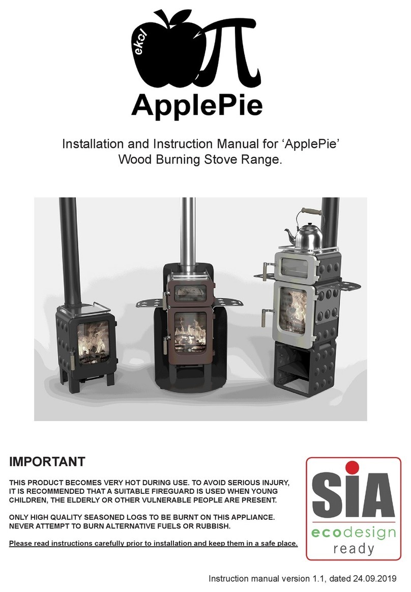
Ekol Clarity 30 Boiler User manual

Ekol Clarity 30 Boiler Woodburning Stove
INSTALLATION AND OPERATING INSTRUCTIONS.
REF: Ekol Claity 30 Boiler Wood Version, MANUAL Version 1.1
MANUAL PUBLICATION DATE: 22.01.2014
Recommended as suitable for exemption under section 21 of The Clean
Air Act 1993 for use within UK Smoke Control Area.

Ekol Clarity 30 Boiler Woodburning Stove, –INSTALLATION AND OPERATING INSTRUCTIONS.
REF: Ekol Clarity 30 Boiler Wood Version, MANUAL VERSION 1.1
DATE: 22.01.2014
INTRODUCTION
SAFETY
Safety is the most important consideration when using and installing your stove. If not installed and used correctly, a house
fire could result. Installation must comply with relevant national and local Building Regulations and fire safety standards.
IN THE EVENT OF CHIMNEY FIRE, EVACUATE THE PROPERTY AND CALL THE EMERGENCY SERVICES.
Your stove will be heavy and care needs to be taken when lifting - 4 people will normally be required to lift.
UNPACKING
Your stove will have several of its components stored inside the stove itself for transportation.
Do NOT drag the stove on its legs –it must be carefully lifted into place.
Inside the stove will be a flue connector collar. This simply bolts with the fixings provided onto the top or rear outlet of the
stove, depending on your choice of installation type. Ensure to secure the supplied circular blanking plate onto the other
outlet using a good bead of fire cement to seal both the collar and the blacking plate.
Inside the stove will also be an ash-pan which sits underneath the grate, and will require regular emptying. You will also find
a detachable tool for removal of the ash-pan.
You will also find a glove which must be used when opening the door or when adjusting air vents when the fire is hot.
There is also a removable baffle plate which rests on the top of the cylindrical section of the water jacket and the rear of the
firebox (see diagram fig1.) this plate can be removed periodically to aid cleaning of the stove flueways and for easier access
to the flue system. It is vital that the baffle is always replaced before use.
INSTALLATION
Installation of your stove must comply with relevant local and national Building Regulations and fire safety standards.
TECHNICAL
Your stove has been tested to CE and British standards conforming to EN 13240.
Model; “Ekol Clarity 30 boiler”
Nominal heat output total –19.2 kW
Nominal output to space –9 kW
Nominal output to water –10.2 kW
Net Weight of Stove - 220 kg.
Max Height - 725 mm (see also Diagram Fig.2)
Max Width - 767 mm
Max Depth - 536 mm
Flue Diameter - 150mm (6”)
Mean flue gas temperature directly downstream of the flue spigot - 322 degrees C. (with closed doors).
Flue gas mass flow –15.8g/s
Mean CO emission (at 13% Oxygen) –0.48%
Net Energy Efficiency 73.8%
Maximum operating water pressure 2 BAR

The stove must not be installed within the specified minimum distances to combustible materials: A gap of at least 200mm
needs to left between the stove and any combustible materials at the sides and 200mm to the rear. Adjacent walls should be of
non-combustible materials and construction, preferably masonry or brickwork.
All combustible items must be kept well clear of the stove, including log store, furniture, curtains etc and any item movable
or otherwise which may pose a fire hazard.
Your stove will require a constant air supply, and should not be used at the same time and in the same room/space as
extractor fans or any device which may draw air supply away from the stove.
The stove should be installed on a level floor with adequate load bearing capacity.
The stove needs to stand on a hearth of non-combustible materials not less than 12mm thick conforming to Building
Regulations.
At least one permanent external air vent should be installed in the same room as the stove, to ensure a constant air supply for
combustion. It should consist of a total free area of at least 10500mm². –ie a square opening of 100mm x 100mm would be
the minimum requirement. The vent should be positioned such that it is not liable to blockage.
NOT suitable for installation in a shared flue system.
If installed in a standard type chimney, a register plate needs to be fitted inside the chimney.
When purchasing flue pipe, 6” diameter is required. The flue pipe must be fitted INSIDE the flue spigot, and sealed with a
generous amount of Fire Cement.
Access should be provided for cleaning the flue gas connector and chimney flue to ensure that the passageways for exhaust
gases remain free from obstruction.
Flue Draught
Flue draught should be measured at full output when up to full operating temperature and must be within the following limits:
12 to 18 Pascals. –If the flue draught at full output exceeds the upper limit, then a suitable flue draught stabiliser must be
fitted to avoid overfiring and to allow sufficient burn-rate control.
We recommend that you have a qualified fitter install your stove. The British recognised standard for solid fuel installations
is HETAS. You can find a HETAS qualified installer in your area by going to the HETAS website –www.hetas.co.uk.
Plumbing
IMPORTANT: - your stove MUST be plumbed in before use. Under no circumstances should it be ‘run dry’ – this
would likely cause significant damage which would not be covered under warranty.
Please note: Saltfire Stoves do not design heating systems. A suitably qualified installer should produce a safe system
design with detailed plans following a site survey. The design should be in conjunction with relevant local and national
Building Regulations.
The information provided below is intended to help as a minimum requirements guide only.
Open Vented Only
Your stove is suitable only for use in open vented systems –this means that it must be installed such that there can be no risk
of the boiler jacket pressurising with increased water temperature. It must never be installed into sealed/ pressurised systems.
However, using safe methods of system ‘link-ups’ your stove can be used when installed safely, in conjunction with other
heating sources which may themselves be sealed systems. An example of this would be to use a thermal store with suitable
automatic control system.
For a traditional basic ‘gravity’ system which enables indirect heating of a DHW (domestic hot water) cylinder and a pumped
radiator heating circuit, a diagram is included in this manual as an example only (Diagram Fig.3) –please note this diagram is

not an installation guide in itself –most importantly, if in doubt, a suitably qualified installer should design a suitable
plumbing system based on your individual situation and requirements.
Drain Cock
A drain cock should be incorporated at the lowest part of the system.
Capacity
The water jacket on your stove has a capacity of 23.7 Litres.
Heat Sink/ Heat Leak
To avoid overheating of the water system in the event of blockage or power failure, or low demand from the heating circuit, a
heat-leak radiator should be incorporated on the gravity part of the circuit. This should have no manual control –ie be
permanently open, and should be connected via 22mm diameter pipe –15mm can be used for final connection to the radiator
for a short distance only. The heat leak radiator should be a minimum 2kW or approx. 6800 BTU.
Rust/Corrosion Inhibitor
Your stove boiler and radiators will be made of steel which will rust/ corrode due to oxidisation.
It is essential that the heating system is filled with the correct concentration of chemical inhibitor such as ‘Sentinel X100’ or
equivalent.
The design of the system regarding pumps and their thermostatic controls should ensure that cold water is never allowed to
circulate –cold water will rapidly increase the risk of corrosion.
OPERATING INSTRUCTIONS
The Clean Air Act 1993 and Smoke Control Areas
Under the Clean Air Act local authorities may declare the whole or part of the district of the authority to be a
smoke control area. It is an offence to emit smoke from a chimney of a building, from a furnace or from any fixed
boiler if located in a designated smoke control area. It is also an offence to acquire an "unauthorised fuel" for use
within a smoke control area unless it is used in an "exempt" appliance ("exempted" from the controls which
generally apply in the smoke control area).
The Secretary of State for Environment, Food and Rural Affairs has powers under the Act to authorise smokeless
fuels or exempt appliances for use in smoke control areas in England. In Scotland and Wales this power rests with
Ministers in the devolved administrations for those countries. Separate legislation, the Clean Air (Northern Ireland)
Order 1981, applies in Northern Ireland. Therefore it is a requirement that fuels burnt or obtained for use in smoke
control areas have been "authorised" in Regulations and that appliances used to burn solid fuel in those areas
(other than "authorised" fuels) have been exempted by an Order made and signed by the Secretary of State or
Minister in the devolved administrations.
The “Ekol Clarity 30 Boiler” has been recommended as suitable for use in smoke control areas when burning
seasoned wood and when used in accordance with these instructions.. The air controls are factory set to allow a
constant amount of combustion air, and must not be modified in anyway.
Further information on the requirements of the Clean Air Act can be found here: http://smokecontrol.defra.gov.uk/
Your local authority is responsible for implementing the Clean Air Act 1993 including designation and supervision
of smoke control areas and you can contact them for details of Clean Air Act requirements
FUEL

Wood- All types of wood are suitable provided they are well seasoned, UNTREATED, and have a moisture level between
12% and 20%. For soft woods, typically they will need to have been left in suitable storage for 9+ months in order for the
moisture to evaporate. For hardwoods, this will usually be 18 months+. It is recommended that logs should be no more than
5” or 125mm in diameter. Logs should be no more than 260mm in length if laid front to back (for best results), or max
400mm if laid left to right in the firebox.. We strongly advise you can buy a moisture meter which will indicate the moisture
levels in your fuel. 80 % of issues with poor performance are due to poor, usually wet fuel. Wood can feel dry on the outside
but be very wet in the middle. To test moisture, split a log, and deeply insert the probes of the meter into the centre of the log.
Liquid fuels must NEVER be used.
WARNING: Wet timber should not be used as this will create excess tar deposits in the chimney and stove and could increase
the risk of chimney fire. Timber which is not of a suitable moisture content will also create more smoke and harmful
emissions.
Never use your stove as incinerator to burn waste or rubbish.
Diagram Fig. 1
AIR INLET CONTROLS
Your stove has four air inlet areas-
1) Vent at bottom part of door –this is the first Primary air vent which allows air to the base of the fire –needs to be
kept open when lighting and briefly when refuelling to allow the firebox to get upto optimum operating temperature
quickly. Moving slider to the left will minimise air flow/ burn rate. Moving to the right fully opens for maximum air
flow.

2) Vent at back of stove, controlled by the thermostat is also a Primary air vent –the thermostat will allow air in initially
but will close when upto temperature. When burning for longer periods, or when the stove is not supervised, all other
vents shut be closed to minimum. If the water temperature exceeds safe limits, the thermostat automatically closes the
rear Primary inlet thus slowing the burn rate to help avoid boiling of the water in the system.
Before use, the operation of the thermostat should be checked when cold –turn the thermostat control dial to
minimum, to ensure that the closure plate sits flush against the stove body. If it doesn’t, it can be further tightened
with a crosshead screwdriver. Once a satisfactory closure is achieved, the control arm can then be opened ready for
use.
3) Vent control at top of door –this is the Secondary or Airwash supply –this vent allows air in which is flushed down
onto the glass helping to keep the glass clean and aiding cleanburning of the gases. Moving slider to the left will
minimise air flow/ burn rate. Moving to the right fully opens for maximum air flow and burn rate.
4) Vent under the stove body –this is the Tertiary air inlet and remains open –it allows air in to a channel behind the
firebox and this air is preheated and introduced into the firebox through a series of small holes at the back of the
firebox. This air supply is essential for clean burning of the fuel and gases.
Diagram Fig.2
Diagram Fig.3 –Example plumbing circuit

TOOLS
The glove is provided for adjusting the air inlets and for opening the door when the stove is hot, as these knobs will heat up
when in use.
NOTE –all parts of the stove will become hot during use and care needs to be taken to avoid injury through burning.
The tool handle provided is for removing the ash-pan.
LIGHTING THE FIRE
Prior to lighting the fire for the first time, ensure that-
Installation and building work is complete.
The chimney is suitable and sound and has been swept and free from obstruction.
Adequate ventilation and provision for combustion air has been made.
That the stove installation has been carried out in accordance with Building Regulations and any applicable local
regulations as well as these installation instructions.
That chimney draw has been checked and within specification. (The stove has been tested at nominal output with a
flue draught of 12 Pa)
ENSURE THAT YOU HAVE READ AND UNDERSTOOD THESE INSTRUCTIONS BEFORE LIGHTING THE
FIRE, AND THAT YOU ARE CONFIDENT THE STOVE HAS BEEN INSTALLED CORRECTLY.

ALWAYS WEAR A PROTECTIVE GLOVE WHEN REFUELLING YOUR STOVE.
Ignition
Ensure the ash-pan is in place.
Ensure all air inlets are fully open
Construct a pile of kindling in the middle of the grate using approximately 1.5kg of kindling wood
Light with a single chemical firelighter
Partially shut the door but leaving it cracked open slightly
After about 5 minutes or when the fire is well established, shut the door
After a further 3-5 minutes as the fire starts to die, add a further four larger pieces of wood weighing approx 3kg.
Once theses logs are alight, and after about 7 minutes or so, a normal load of 4 to 6 logs weighing approximately
5kgs in total can be added
Once this load is burning well, the Primary air vents can be closed, with the Secondary and Tertiary vents left open.
Refuelling
Open the Primary air vents
Add up to a maximum 5kg of wood
After about 2 minutes or when flames from the fresh fuel fully established, close the Primary vents
At high power output, your stove will require refuelling approximately every hour.
It is important to follow these instructions in order to achieve clean burning and to maximise the efficiency of the
stove
Do not leave the fire unattended until flames are well established an the newly charged logs
Always refuel onto hot embers.
If the fire has died out at the point of refuelling, or if there is insufficient burning material in the firebed to light a new
fuel charge, excessive smoke emission can occur. Refuelling must be carried out onto a sufficient quantity of glowing
embers and ash that the new fuel charge will ignite in a reasonable period. If there are too few embers in the fire bed,
add suitable kindling to prevent excessive smoke, re-establish the fire and follow the “Ignition” process above. It is
important that the stove is not overloaded with fuel.
It is important that the stove is not overloaded with fuel.
Reduced burn rates can be achieved by reducing the openings of the Secondary and Tertiary air vents.
Operation with the door open can cause excessive smoke. The appliance must not be operated with the door left open
except as directed in the instructions above.
Air vents should not be left open fully unless where described in this manual leaving air controls open could lead to
essessive draft or could cause smoke emission.
IMPORTANT NOTE ON OVERFIRING
Your stove should NOT be used for extended periods with all vents fully open and should never be used with the doors open
except when refuelling. –this is likely to cause over-firing, excessive temperatures which will lead to premature damage/
buckling and warping of internal components and in some cases the stove body itself. Overfiring can also be caused by
excessive flue draught. Such damage will not be covered under the warranty.
UK Clean Air Act 1993 - Smoke Control Areas
The “Ekol Clarity 30 Boiler”wood burning stove has been recommended as suitable for use in smoke control areas when
burning seasoned wood and when used in accordance with these instructions.. The air controls are factory set to allow a
constant amount of combustion air, and must not be modified in anyway.
WARNING- The high temperature paint covering the stove will give off some fumes during the initial few uses of the stove.
The fumes are non-toxic, but some people may find them unpleasant –Ensure the area is well ventilated during this period.
The output ratings of this stove are based on around 5kg of seasoned logs which would require refuelling every hour.

This stove is suitable for intermittent burning, and should not be used constantly for extended periods. Not suitable for
overnight burning.
Under certain abnormal weather conditions, e.g. down draughts, it may be difficult to get sufficient draw through the
appliance to achieve good combustion. When this happens, the stove should not be used.
CLEANING/MAINTENANCE
Regular cleaning of the stove is essential for safety and efficiency. The ash-pan should be emptied at least after every use, and
during use if burning for longer periods.
When cold, the inside of the stove should be given a regular sweep out.
The flue and flue pipe will require cleaning with a suitable chimney brush, to minimise build up of soot and tar.
The baffle plate inside the stove can be simply lifted out for easy access to the flueways (see Diagram Fig.1)
You chimney will also require periodic sweeping.
If the glass becomes stained from the inside, the air-wash vent may need opening more during use. The glass can be cleaned
with a cloth and chemical stove glass cleaner, or the glass cleaning pad made by Schott.
The high temperature paint which your stove is finished in should last many years with normal use, but when it does
eventually require re-finishing, black heat resistant paint in spray cans can be purchased from most hardware stores. –Do not
use regular paint which is not high temperature resistant.
After prolonged periods of not using the fire, the stove and flue system should be checked for blockages prior to re-lighting.
We recommend regular servicing and safety checks are carried out by a qualified engineer.
There must be no unauthorised modification of the appliance. Use only replacement parts recommended by the
manufacturer.
What to do in the event of a chimney fire:-
cut off the air supply to the stove, i.e. close the primary and secondary air supplies
move any combustible materials well-away from the stove
get everyone out safely
make sure that the fire brigade has clear access
call 999
If you have any questions or concerns regarding the safe use of your stove, please contact us.
Warranty
Your stove is guaranteed to be free from manufacturing defects which would affect the performance of the stove.
When supplied through an authorised dealer and when registered, your guarantee will extend to 5 years and is limited to the
original purchaser and the original installation/ address.
Guarantee terms are for supply of replacement parts only, returned to factory and does not include Grates, firebricks, glass,
rope seals, paint, baffles, or internal lining plates.
Claims for damage caused by incorrect use or installation, damage caused by over-firing or use of incorrect fuels and
accidental damage will not be accepted.
Copyright Saltfire Stoves Ltd, 2014

-Reproduction of this document in whole or in part is prohibited unless written permission has been granted by
Saltfire Stoves Ltd, Johns Road, Wareham, Dorset, UK, BH20 4BG.
Customer Service - +44 (0)1929 555211.
Table of contents
Other Ekol Wood Stove manuals
Popular Wood Stove manuals by other brands

Century Heating
Century Heating FW3000 Installation and operation manual
HWAM
HWAM 3410S user manual

RAIS
RAIS RAIS Q-BIC user manual
Dovre
Dovre TAI 45WT Installation instructions and operation manual

England's Stove Works
England's Stove Works 25-CAB80 Installation & operation manual
HearthStone
HearthStone Green Mountain Insert 90 owner's manual
Eureka
Eureka Jindara Duet SRS2/Duplicity installation instructions
Osburn
Osburn 900 owner's manual
Ravelli
Ravelli Flexi 9 Use and maintenance manual
Heta
Heta Scan-line 7 Series Operating and installation instructions
barbas
barbas BOX30 75 user manual
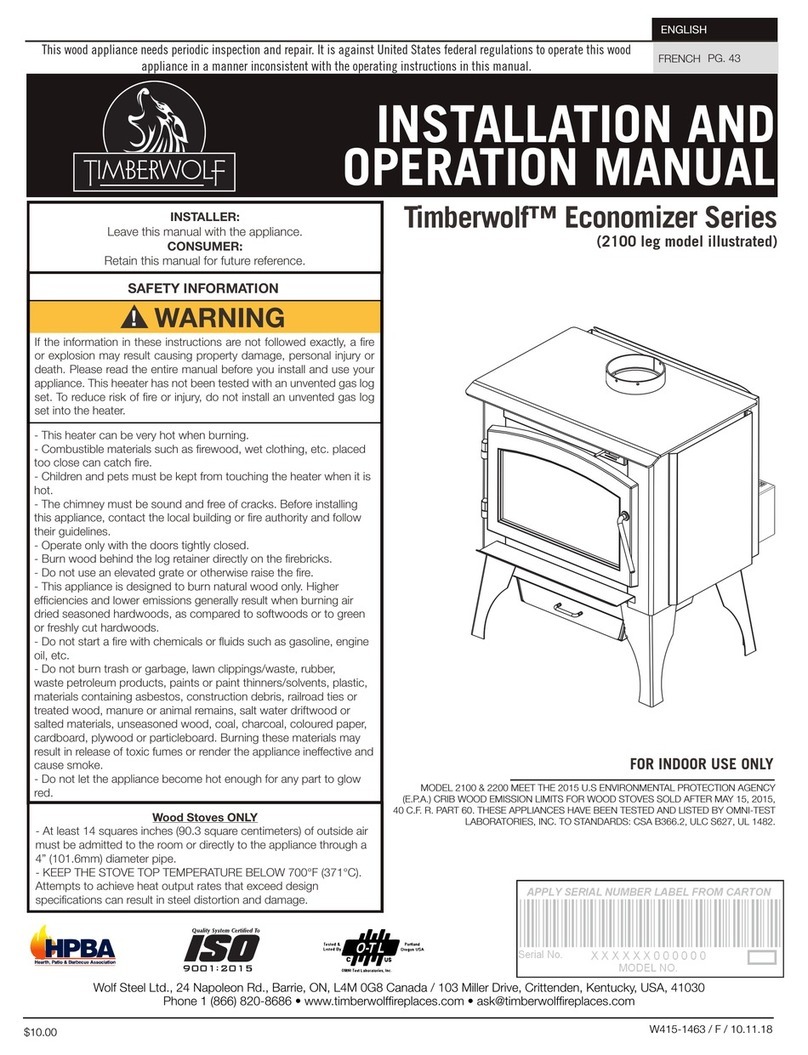
Timberwolf
Timberwolf Economizer Series Installation and operation manual

