ektor 1808 User manual

1. WELCOME
Installation Instructions
CONTENTS
CODE: 1808, 1810, 1812, 1814
CODE: 1809, 1811, 1813, 1815
1.
2.
3.
4.
5.
6.
7.
8.
9.
10.
11.
12.
13.
14.
15.
16.
17.
18.
19.
20.
21.
22.
23.
24.
25.
26.
27.
28.
29.
30.
31.
Thank you for choosing this quality Ektor product.
This manual is intended to help you install this
product in a way that ensures the safety of yourself
and others. Whilst this Ektor product is designed
to be installed easily, we highly recommend you
take the time to read this manual thoroughly before
commencing installation. When installed correctly
and serviced regularly, this product will provide
hassle free operation for many years.
1
Welcome
Overview
Safety warnings
Installation
Mounting
Terminal block wiring
Self-test wiring / central battery system
DALI wiring / central battery system
Using the inverter with a switch
Using the inverter with a sensor
Using the inverter with an onboard microwave sensor
Maintaining your Circular Pearl luminaire
Replacing the battery
Battery life
Power and battery charge
Wireless daughterboard
Non maintained / maintained jumper
Discharge rating selection
Onboard microwave sensor settings
Accessories list
Self-test indicator LEDs
Self-test / commissioning interval programming
Product specifications
Australian emergency classification
Spacing table
Construction sites
Testing precautions
Problem solving procedure
Warranty information
Compliance standards
Technical support and troubleshooting
MANUFACTURED
TO ISO9001
1808 EV-PEARL-EM-WP
1809 EV-PEARL-EM-PRO-WP
1810 EV-PEARL-WP
1811 EV-PEARL-PRO-WP
1812 EV-PEARL-EM-WP-S
1813 EV-PEARL-EM-PRO-WP-S
1814 EV-PEARL-WP-S
1815 EV-PEARL-PRO-WP-S

CIRCULAR PEARL EMERGENCY INSTALLATION INSTRUCTIONS
2. OVERVIEW
Ektor Generation III platform introduces you to a new era of emergency lighting control. With years in the
making, the third generation platform builds on the Ektor product ranges’ increasing quality, reliability and
performance. In choosing this Ektor product you can be comfortable that you have the best.
This product out of the box can be wired in any of these configurations:
• Self testing unit
• Standalone unit
• Standalone unit controlled with a switch or sensor
• DALI controlled remote testing unit
And can be used with a central battery system (monitored and non-monitored)
An optional wireless module can be added to allow you to connect to standard Wi-Fi networks for remote
testing and reporting.
Our Ektor Generation III platform also brings class leading technology which increases performance and
reliability including:
• Smart battery charging technology which reduces power consumption up to 90% while
increasing the service life of the battery
• Smart battery conditioning to ensure the best performance from the battery
• 450V Electrolytic capacitors which increase the products reliability
• Highly efficient design to reduce fatigue on the product
For buildings requiring longer durations such as 3, 4 and 8 hours the installer can change the jumpers found
on the unit for automatic scaling of the output.
2
3. SAFETY WARNINGS
1. THIS PRODUCT MUST ONLY BE INSTALLED BY A LICENSED ELECTRICIAN.
2. BEFORE COMMENCING INSTALLATION TURN OFF AND ISOLATE THE ELECTRICAL SUPPLY.
3. DO NOT ENERGISE WITH PRODUCT OPEN OR DISASSEMBLED.
4. SUPPLY VOLTAGES WITHIN PRODUCT. ISOLATE SUPPLY VOLTAGES BEFORE OPENING OR SERVICING.
5. THE ONLY USER SERVICEABLE PART IS THE BATTERY PACK.
6. DO NOT ATTEMPT TO SERVICE OTHER PARTS OF THE FITTING AS THIS WILL VOID THE WARRANTY.
7. AS THE INSTALLER, IT IS YOUR RESPONSIBILITY TO ENSURE YOU COMPLY TO ALL RELEVANT BUILDING AND SAFETY
CODES FOR EXAMPLE THE BCA, AS3000. REFER TO APPLICATION STANDARDS FOR THE RELEVANT RULES.
8. WHEN THE INSTALLATION IS COMPLETE, LEAVE THIS MANUAL WITH THE BUILDING’S OWNER(S) FOR FUTURE REFERENCE.
CIRCULAR PEARL EMERGENCY INSTALLATION INSTRUCTIONS
4. INSTALLATION
The Ektor Weatherproof Circular can be installed by mounting the product to the ceiling. To install the
Circular please follow the steps listed below:
1. Remove the product from the box and inspect it for any damage. If you believe the product to be
damaged or otherwise unsound, DO NOT install the product. Please pack it back into its box and return
it to the place of purchase for replacement. If the product is satisfactory, proceed with the installation.
2. When mounted the Circular cover MUST be opened. Open the cover by releasing the clasps and swing
the cover upwards by its hinge as shown below. This will allow for the gear tray to become visible.
3. Locate the screw(s) holding the gear tray in place, unscrew it and swing the gear tray upwards.
4. The cover is to be released for mounting the Circular, battery replacement and servicing.
NOTE: No tools should be
used to release the clasps
Circular cover
Circular cover
Gear tray
Clasps
Figure 1: Circular installation
3
CIRCULAR PEARL EMERGENCY INSTALLATION INSTRUCTIONS
5. MOUNTING
Before you start mounting your Circular, the access point for the terminal block wiring must be chosen.
There are three different access points(A, B, C), option C is specificaly for conduit entry.
1. Drill a hole through the Circular base in the desired position. Route the wiring for the terminal block
through the holes and the supplied weatherproof gland.
2. Move the Circular into position on the ceiling and mount by fastening the screws securely to the flat
surface with the use of the supplied washers.
3. Wire the terminal block as shown in section 6 (page 5), tighten cables into the strain relief and
reassemble cover as in steps 2 and 3.
CEILING MOUNT
Figure 2: Ceiling mount
4
6 gage screws
not supplied
Strain relief
NOTE: Optional maisonary anchors/raw plugs are supplied
A
B
C
Washers
supplied

CIRCULAR PEARL EMERGENCY INSTALLATION INSTRUCTIONS
E
E
E
E
5
6. TERMINAL BLOCK WIRING OPTIONS
The wiring for Circular differs between models and accessories installed. Wiring schematics for the terminal
blocks used with the Circulars in the following sections.
Figure 3:
Mains operation only
Figure 4:
Emergency models
EV-PEARL & EV-PEARL-PRO
EV-PEARL-EM & EV-PEAR-EM-PRO
Standard DALI emergency
External sensor
External switchExternal sensor
Unswitched activeUnswitched active
ActiveActive
Optional Optional
Optional Optional
Standard
E
Switched
EE

CIRCULAR PEARL EMERGENCY INSTALLATION INSTRUCTIONS
E
6
8. DALI WIRING/ CENTRAL BATTERY SYSTEM
The Circular inverter supports DALI out of the box, illustrated in the hardwiring diagram
shown below. The inverter also supports central battery systems and can be monitored through DALI. When
used as a central battery system the devices can be tested with DALI. See wiring diagram in section 6 (page 5).
7. SELF-TEST/ STANDARD WIRING/ CENTRAL BATTERY SYSTEM
In emergency models the inverter can be used in an automatic self-test mode which reduces the need for a test
switch timer.The self-test ability automatically disables if the unit is wired to DALI or the wireless daughterboard
is attached. Additionally the third generation platform can be wired to a central battery system. With this wiring
the system cannot report the light status (see Self test support document for more information).
NOTE: Emergency models with microwave sensors do not support central battery as regular and emergency power is not separated.
Figure 5:
Microwave models
EE
Figure 6: Emergency
microwave models
Sensor out
Optional
Sensor out
Optional
Combined input
Sensor out
Optional
Sensor out
Optional
Internal
sensor
Internal
sensor
Internal
sensor
Internal
sensor
E
EV-PEARL-S & EV-PEAR-PRO-S
EV-PEARL-EM-S & EV-PEAR-EM-PRO-S
Standard Switched
Standard DALI emergency

CIRCULAR PEARL EMERGENCY INSTALLATION INSTRUCTIONS
7
9. USING THE INVERTER WITH A SWITCH
10. USING THE INVERTER WITH AN EXTERNAL SENSOR
A mains rated switch can be wired with this product to turn ON/OFF the non-emergency light in normal use.
This does not affect operation in emergency mode. See external switch wiring diagram in section 6 (page 5).
A mains rated sensor can be wired with this product to turn ON/OFF the light in normal use. This does not
affect operation in emergency mode. See external sensor wiring diagram in section 6 (page 5).
11. USING THE INVERTER WITH AN ONBOARD MICROWAVE SENSOR
For models 1812-1815 an onboard sensor is available. In addition to switching the internal light the L’ terminal
can be used as a power supply for up tp 14 additional Circular lights.
NOTE: Emergency models with microwave sensors do not support an external switch.
NOTE: Emergency models with microwave sensors do not support an external sensor
13. REPLACING THE BATTERY
12. MAINTAINING YOUR CIRCULAR PEARL LUMINAIRE
1. Use only the LiFePO4 battery recommended on the label found on the inverter/battery charger pack.
No other battery will work in this fitting, other than the type listed.
2. Access the battery by releasing the product cover as shown in section 4 (page 3) of this manual.
3. Disconnect the battery from the product and if necessary, cut cable ties to release the battery from its
mounting position.
4. Replace the battery as was previously installed and secure with cable ties.
5. Put the Circular back into its previously mounted ceiling position and ensure the green charge light is
illuminated. Allow a few minutes for the battery to charge.
6. Allow a minimum 24 hours charging time before carrying out any discharge tests as per the requirements
in AS/NZS 2293, BCA or other relevant standards.
The Circular is connected to an unswitched active during normal operating conditions.
When disconnected from the mains supply, the Circular is powered by a LiFePO4 battery operated inverter.
Due to this, care should be taken when replacing the battery.
WARNING
CIRCULAR PEARL EMERGENCY INSTALLATION INSTRUCTIONS
8
Charge
current
Max charge current Max charge voltage Savings
Cell voltage
15. POWER AND BATTERY CHARGE
The Ektor Generation III platform uses smart battery charging technology which reduces power consumption
and increases battery life.
During the first stage of operation the battery charger charges the battery until full. Afterwards, the unit goes
into a stage which charges the battery periodically. This reduces the battery temperature and reduces the
loss of electrolytes which ultimately increases the service life of the battery.
The smart battery charger also offsets the charging time by a random interval to un-synchronise all the
emergency lighting in the building. This reduces the average loading on a building’s infrastructure and reduces
any impacts of surges created by turning on large numbers of products simultaneously.
Figure 8: Smart charge rate
14. BATTERY LIFE
The economical life of the battery installed in this unit is 4 years; it is recommended that the battery is replaced
after this time. To maintain the economical life of this product it is required that the battery be discharged
and recharged at least once every 6 months. The battery life can be reduced if the battery is not discharged
as per the requirements of AS/NZS 2293 or an equivalent standard. Increasing the number of duration tests
above that as defined in AS/NZS 2293 or an equivalent standard can have a positive effect on the battery
performance as long as 12 discharge cycles per year is not exceeded.
Figure 7: Example of included battery
1 x LiFePO4 battery (1302, 1303)
KIT INCLUDES:
1

CIRCULAR PEARL EMERGENCY INSTALLATION INSTRUCTIONS
9
17. NON MAINTAINED/ MAINTAINED JUMPER
The Emergency light in the Circular is de designer for use in no-maintained mode only.
Figure 10: Maintained/non-maintained jumper
Jumper
INDICATOR STATUS DESCRIPTION
NON MAINTAINED
MAINTAINED MODE
LED is only ON in
emergency
Not supported
18. DISCHARGE RATING SELECTION
The inverter supports a number of discharge ratings which can be selected by the user. The output from
the LED scale based on the discharge rating (see ektor.com.au for output information).
Figure 11: Discharge rating selection
Remove expansion cover
C
B
A
HOURS A B C
1 hour
2 hours (default)
3 hours
4 hours
Central battery operation
N/A
N/A
OFF
ON
ON
ON
OFF
OFF
OFF
OFF
ON
ON
OFF
ON
ON
OFF
OFF
ON
OFF
ON
OFF
ON
ON
16. WIRELESS DAUGHTERBOARD
The Circular inverter used in emergency models also support an optional wireless daughterboard. The driver
must be disconnected from mains and battery must be removed, before installing or changing any expansion
module. More information and a list of other accessories can be found in the Wireless design and installation
guide. The assembly for this part onto the inverter is shown below:
Figure 9: Daughterboard assembly diagram
2
1
Wireless daughterboard (6118)(optional)
Circular inverter (1222, 1223, 1224, 1225)
1
2
CIRCULAR PEARL EMERGENCY INSTALLATION INSTRUCTIONS
10
The daylight threshold can be set on DIP switches, to fit for particular applications.
DAYLIGHT SENSOR
ON
OFF
Daylight: The lamp works always, even during daylight
Twilight: The lamp works only in twilight and darkness
Darkness: The lamp works only in darkness
LUX OPERATION789
2lux darkness operation only
5lux darkness operation only
20lux twilight operation
30lux twilight operation
Daylight sensor disabled (default)
I
II
III
IV
V
Figure 12: Microwave sensor
19. ONBOARD MICROWAVE SENSOR SETTINGS
Detection area can be reduced by selecting the combination on the DIP switches to fit precisely for each
specific application.
DETECTION AREA
ON
OFF
RANGE
1
2 3
100% (default)
75%
50%
30%
10%
I
II
III
IV
V
ON DIP
The time period you would like to keep the lamp on 100% after the person has left the detection area.
HOLD TIME
ON
OFF
TIME4 5 6
5 sec (walk test mode)
30 sec
180 sec
300 sec (default)
15 min
25 min
I
II
III
IV
V
VI

CIRCULAR PEARL EMERGENCY INSTALLATION INSTRUCTIONS
11
20. ACCESSORIES LIST
Below are the listings of the accessories and replacements compatible with the Circular.
PART CODEEVOLT CODE
COMPLETE UNITS
Circular Emergency Weatherproof
Circular Pro Emergency Weatherproof
Circular Weatherproof
Circular Pro Weatherproof
Circular Emergency Weatherproof (with Sensor)
Circular Pro Emergency Weatherproof (with Sensor)
Circular Weatherproof (with Sensor)
Circular Pro Weatherproof (with Sensor)
1808
1809
1810
1811
1812
1813
1814
1815
PARTS/REPLACEMENTS
Circular Emergency Weatherproof Inverter
Circular Emergency Weatherproof Pro Inverter
Circular Emergency Weatherproof with Sensor Inverter
Circular Emergency Weatherproof with Sensor Pro Inverter
Battery 1500mAh 2 Cell LiFePO4 Battery
Battery 3000mAh 2 Cell LiFePO4 Battery
Wireless Daughterboard
Easy commissioning module - DALI
Easy commissioning module - EKTOR
Microwave Sensor
EV-PEARL-EM-WP
EV-PEARL-EM-PRO-WP
EV-PEARL-WP
EV-PEARL-PRO-WP
EV-PEARL-EM-WP-S
EV-PEARL-EM-PRO-WP-S
EV-PEARL-WP-S
EV-PEARL-PRO-WP-S
EV-PEARL-EM-WP-INV
EV-PEARL-EM-WP-PRO-INV
EV-PEARL-EM-WP-S-INV
EV-PEARL-EM-WP-S-PRO-INV
EV-1500mAh-64V-LiFePO4
EV-3000mAh-64V-LiFePO4
EV-DAUGHTER-DAUG
EV-ECM-DALI
EV-ECM-EKTOR
EV-MICROWAVE-SENS
1222
1223
1224
1225
1302
1303
6118
5304
5305
6124
21. SELF TEST INDICATOR LEDS
The table below shows the operation of the Circular status indicators:
INDICATOR DESCRIPTION
YELLOW
2sec ON / 2sec OFF
YELLOW
4sec ON / 1sec OFF
YELLOW
0.5sec ON / 0.5sec OFF
GREEN
1xFlash
Device is performing a duration test
Last duration test passed. The duration was met when last run.
Test ran less than five days ago
Last duration test failed. Failed to meet duration. The device is not
currently running a new test. Mains is on
A duration test is pending. The device is not in any self test and is
set to normal mode

CIRCULAR PEARL EMERGENCY INSTALLATION INSTRUCTIONS
12
22. SELF TEST/ COMMISSIONING INTERVAL PROGRAMMING
The self test mode must first be enabled to perform tests by switching the emergency power breaker, or
test button in the correct sequence. The test interval is fixed and set to 26 weeks / 182 days. The LEDs
indicate the status of the device and which functions are being performed. For more information refer to the
Configurations: Status LEDs and Device Modes document.
When self test mode is enabled the status LED will flash either 4x (switched active detected)
or 3x (switched active not detected) for 2 minutes.
The self test can also be enabled using the test button sequence below:
3X PRESS & RELEASE WAIT & REPEAT
WAIT 30 sec.
then repeat the
3X press & release
NOTE: If the wait in-between breaker or test button push sequences is longer than 50 seconds
then it will timeout and the procedure will need to begin again.
30 sec.
RELEASEPRESS RELEASEPRESS RELEASEPRESS
8 sec.
5X SWITCH CYCLES WAIT & REPEAT
WAIT 30 sec.
then repeat the
5X SWITCH CYCLE
OFF ON
OFF ON
OFF ON
OFF ON
OFF ON
30 sec.
8 sec.
CIRCULAR PEARL EMERGENCY INSTALLATION INSTRUCTIONS
13
Voltage (V)
Frequency (Hz)
Max. ambient temp.
Battery type
Class
Duration
IP rating
L’ Output
Evolt code
EV-PEARL-EM-WP
EV-PEARL-EM-PRO-WP
EV-PEARL-WP
EV-PEARL-PRO-WP
EV-PEARL-EM-WP-S
EV-PEARL-EM-PRO-WP-S
EV-PEARL-WP-S
EV-PEARL-PRO-WP-S
Viewing distance
Mounting type
Wiring
Battery voltage
Charging time
Charger operation
Charger type
Code
1808
1809
1810
1811
1812
1813
1814
1815
N/A
Ceiling mounted
Hard wired
6.4V
16 hours
Multi state
Smart charge
Max. power
21 W
29 W
18 W
26 W
22 W
30 W
19 W
27 W
220~240V
50Hz
40°C
LiFePO4
1
Dependant on jumper
IP65
400 W Max.
Name
Circular Emergency Weatherproof
Circular Pro Emergency Weatherproof
Circular Weatherproof
Circular Pro Weatherproof
Circular Emergency Weatherproof w. Sensor
Circular Pro Emergency Weatherproof w. Sensor
Circular Weatherproof w. Sensor
Circular Pro Weatherproof w. Sensor
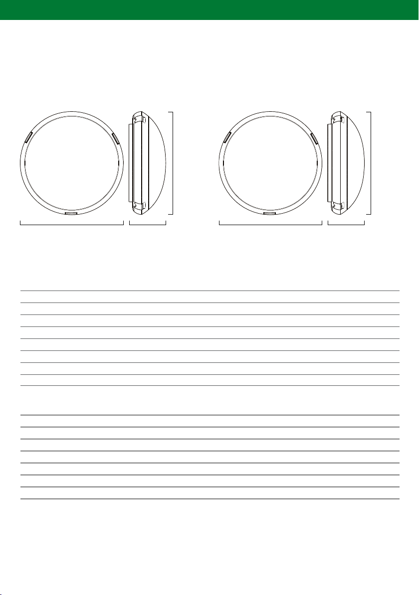
23. PRODUCT SPECIFICATIONS
CIRCULAR CIRCULAR PRO
350mm 430mm
350mm 430mm125mm 135mm

CIRCULAR PEARL EMERGENCY INSTALLATION INSTRUCTIONS
14
25. SPACING TABLE
24. AUSTRALIAN EMERGENCY CLASSIFICATION
Below is the spacing table extract from AS/NZS2293 which details spacing between emergency fittings at
different mounting heights.
Classification of the Circular output when duration is selected.
26. CONSTRUCTION SITES
IMPORTANT NOTE: Continuously switching the power supply to the fitting on and off during or after
the installation process due to other processes being conducted on the building site could cause the fitting to
discharge and charge its battery many times during a short period which can impact negatively on the battery
life. It is not recommended that you connect the Ektor emergency products to the power supply if such
conditions are prevalent. If you choose to expose the Ektor emergency products to such harsh operating
conditions, Evolt may not honour any warranty on the life of the batteries or the dish. This Ektor emergency
product is designed to undergo regular discharge tests but it is recommended that the intervals between
consecutive tests are not less than two weeks. Frequent testing of the exit product will reduce the service life
of the battery. In order to prevent damage to the battery, leave the unswitched active circuit turned off at the
circuit breaker until such time as emergency lighting is required
CIRCULAR PEARL PRO
D40
D40
D25
D16
D10
HOURS CIRCULAR PEARL
1
2
3
4
8
D32
D32
D16
D10
D6.3
LUMINAIRE
CLASSIFICATION
MOUNTING HEIGHT (M)
2.1 2.4 2.7 3 3.3 3.6 4 4.5 5 6 7 8 9 10 15 20
D6.3
D10
D16
D25
D32
D40
8.6
10.2
12.1
14.2
15.4
16.7
8.8
10.6
12.6
14.7
16.1
17.4
9.0
10.9
13.0
15.3
16.7
18.0
9.1
11.1
13.3
15.7
17.2
18.6
9.2
11.3
13.6
16.1
17.6
19.1
9.2
11.4
13.9
16.5
18.0
19.6
9.2
11.5
14.1
16.9
18.5
20.1
9.0
11.6
14.6
17.3
19.1
20.8
8.7
11.6
14.6
17.7
19.5
21.3
7.7
11.2
14.6
18.1
20.2
22.1
5.7
10.3
14.4
18.3
20.6
22.7
8.9
13.8
18.2
20.7
23.0
6.7
12.9
17.9
20.6
23.1
11.5
17.3
20.3
23.1
7.7
14.6
19.4

CIRCULAR PEARL EMERGENCY INSTALLATION INSTRUCTIONS
15
27. TESTING PRECAUTIONS
When the Ektor emergency product is permanently connected to the mains supply you will need to allow 24
hours to charge its battery. Once the battery is fully charged you will need to conduct a manual discharge test
as per the requirements of AS/NZS 2293 or other relevant standards. At the time of printing, the Australian
standard requires that new fittings operate in emergency mode for at least 2 hours for their first discharge
test. Further tests are to be carried out at intervals of not more than six months. It is important that you keep
records of the initial test and ongoing tests in the building’s emergency service logbook. If the fitting is not to be
permanently connected to the mains supply at the time of installation, you must give it the mandatory 2 hour
test when you connect it permanently to the mains supply.
28. PROBLEM SOLVING PROCEDURE
If you have installed and connected the Ektor Circular as per the instructions contained within this manual and
the product fails to work properly, please use the following table as a guide to fixing the problem before calling
our office.
FAULT POSSIBLE CAUSES
Green LED is not lit
Green LED is lit but the lamp does not light when the test
switch is pressed
Lamp lights, but only temporarily, when test switch is
pressed or when the main power supply is turned off
• AC Supply is not connected
• AC Supply turned off
• Battery plug not connected to battery pack
• Lamp is damaged
• Lamp is not inserted properly
• Battery pack is damaged
• Battery pack not fully charged
• Battery pack is damaged

CIRCULAR PEARL EMERGENCY INSTALLATION INSTRUCTIONS
16
29. WARRANTY INFORMATION
Ektor products are distributed in Australia and New Zealand by Evolt Pty Ltd (Evolt).
The Australian Consumer Law as well as other Australian laws guarantee certain conditions, warranties and
undertakings, and give you other legal rights, in relation to the quality and fitness for purpose of Ektor products
sold in Australia.
In Australia, our goods come with guarantees that cannot be excluded under the Australian Consumer Law. You
are entitled to a replacement or refund for a major failure and compensation for any other reasonably foreseeable
loss or damage. You are also entitled to have the goods repaired or replaced if the goods fail to be of acceptable
quality and the failure does not amount to a major failure. What constitutes a major failure is set out in the
Australian Consumer Law.
Nothing in this Warranty purports to modify or exclude the conditions, warranties and undertakings, and other
legal rights, under the Australian Competition and Consumer Act and other Australian laws.
Ektor products are warranted in Australia for a period of 12 months from the date of delivery of the product,
provided that the products are properly stored, installed, used and maintained in accordance with the instructions
contained within their manual.
Products that have been altered in any way or used other than in accordance with their instructions are not
covered by this Warranty.
This Warranty is not transferable and is valid only in the hands of the purchaser of the product. The warranty
does not cover Ektor products other than those purchased from Evolt. Proof of purchase must be provided to
Evolt with any warranty claim. Evolt recommends that the purchaser attaches their proof of purchase to their
product manual.
If you wish to claim under this Warranty, you must, at your own expense, return the product or that part of
the product which you believe is defective, and proof of original purchase, your name, address and telephone
number and a certificate of installation or other document required by the law for the installation of electrical
products in the place in which the product was installed, to Evolt at the address above within 12 months from the
date of purchase. Please note that the Warranty does not cover removal or reinstallation of the product or that
part of the product which you believe is defective.
Evolt’s total liability under this Warranty is limited to the cost of repair or replacement of the faulty product. Evolt
may satisfy its obligations under this Warranty in full by repair or replacement of a faulty product.
This Warranty does not apply to consumable items such as lamps or batteries or other items that can be classified
as consumable.
For the avoidance of any doubt, any and all warranties or conditions which are not guaranteed under the
Australian Competition and Consumer Act or the Australian Competition and Consumer Regulations 2010 and
which are not expressly included in this Warranty as additional warranties or conditions are excluded.
This Warranty does not cover loss or damage caused by wear and tear, misuse, incorrect installation or
operation, failure to clean and maintain, incorrect voltage or non-authorised electrical connections, adverse
external conditions (such as power surges and dips, acts of God, exposure to heat, corrosion, insect or vermin
infestation), use of non-authorised or defective parts or globes, or to items that have been repaired other than by
Evolt or a repairer approved by Evolt.
CIRCULAR PEARL EMERGENCY INSTALLATION INSTRUCTIONS
30. COMPLIANCE STANDARDS
STANDARD TITLE
Australian/ New Zealand
Standards
AS/NZS 2293-3:2005+A1:2010
AS/NZS 60598-2-22:2005
AS 61000.3.2:2007 + A1:2009
AS/NZS CISPR 15:2011
Emergency escape lighting and exit signs for buildings.
Part 3: Emergency escape luminaires and exit signs.
Luminaires Part 2.22: Particular requirements - Luminaires for
emergency lighting (IEC 60598-2-22, Ed. 3.1(2002) MOD).
Electromagnetic compatibility (EMC) - Limits - Limits for
harmonic current emissions (equipment input current
(16 A per phase) (IEC 61000-3-2, Ed.3.0 (2005) MOD).
Limits and methods of measurement of radio disturbance
characteristics of electrical lighting and similar equipment.
European Committee
for Standardisation
EN 60598-1:2008+A11:2009
EN 60598-2-22:1998+A1:2003+A2:2008
EN 55015:2006+A1:2007+A2:2009
EN 61547:2009
EN 61000-3-2:2006+A1:2009+A2:2009
EN 61000-3-3: 2008
Luminaires - Part 1: General requirements and tests.
Luminaires - Part 2-22: Particular requirements -
Luminaires for emergency lighting.
Limits and methods of measurement of radio disturbance
characteristics of electrical lighting and similar equipment.
Equipment for general lighting purposes - Electromagnetic
compatibility (EMC) immunity requirements.
Electromagnetic compatibility (EMC) Limits. Limits for
harmonic current emissions (equipment input current ≤
16 A per phase).
Electromagnetic compatibility (EMC) - Part 3-3: Limits -
Limitation of voltage changes, voltage fluctuations
and flicker in public low-voltage supply systems, for
equipment with rated current <= 16 A per phase and
not subject to conditional connection.
17
31. TECHNICAL SUPPORT AND TROUBLESHOOTING
For further assistance in using this product, consult your nearest wholesaler or Evolt Pty Ltd. Be aware that
illustrations and images used are for illustration purposes only and changes may apply to products after the
release of this document.

CIRCULAR PEARL EMERGENCY INSTALLATION INSTRUCTIONS
18

CIRCULAR PEARL EMERGENCY INSTALLATION INSTRUCTIONS
19

This manual suits for next models
7
Table of contents
Other ektor Lighting Equipment manuals


