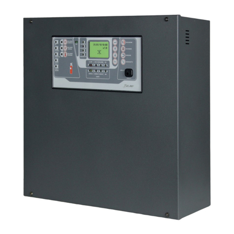
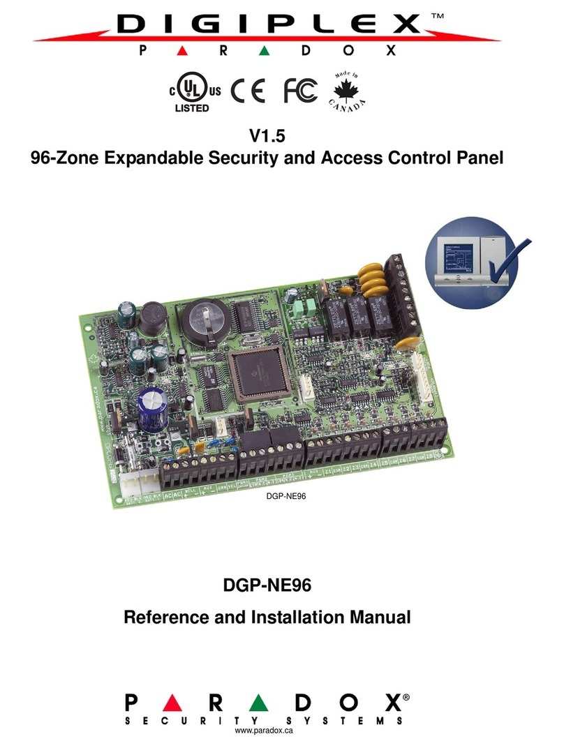
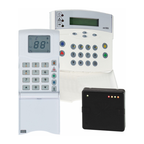
EL.MO. Spa TA1002 User manual

111
User manUal
Control panels and signalling equipment
TACÓRA SERIES
1 DECLARATION OF CONFORMITY
AND PERFORMANCE
13
TA1002: No. 0051 – CPR – 0402
TA1004: No. 0051 – CPR – 0403
TA2000: No. 0051 – CPR – 0401
17
TA4000: No. 0051 – CPR – 0515
Standards: EN 54-2:1997/A1:2006
EN 54-4:1997/A1:2002/A2:2006
2 GENERALS
TACÓRA series control and signalling equipment can man-
age a fire detection system devices, monitoring up to 45
dierent zones.
Model TA1002 TA1004 TA2000 TA4000
MCP (call points) 1 1 1 1
Conventional zones 2 4 12 4
Analogue-addressable
loops
- - 1 (zones
13-44)
2 (zones
5-44)
Total zones 3 5 45 45
Control panels are compatible with EXTING extinguishing
module and MDGSME SMS sender module.
3 ACCESS LEVELS
Panels functions can be accessed according to three dier-
ent access levels:
• level 1 (public) – no password needed
• level 2 (user) – dedicated key required
• level 3 (maintenance/programming) – accessible for au-
thorised personnel only
Level 1 grants access to all functions available to everyone,
such as those for panel general monitoring.
At level 2, setup menu will be displayed.
To go back to level 1, turn and remove the key.
If a control panel at level 2 receives no inputs from the front
keypad for 15 minutes, the LCD backlight will start blinking
and the last row of the display will show "Panel on level 2"
message.
Pressing any keys makes the message disappear for 15 min-
utes, but the display will keep blinking until the panel goes
back to level 1.
4 FRONT PANEL
The control panels can be managed by the front keypad or
by a connected TAREPEATER keypad.
All status and functions of the control panels are shown and
managed via panel LCD and the coloured LED indicators.
The available control buttons provide for easy configuration
and control operations.
The display backlight colour will change according to panel
status.
GREEN - standard working mode

2
YELLOW - fault/anomaly indication
RED - alarm/pre-alarm indication
White - setup indication
Fault (or alarm) indications include, at the bottom right, the
number of the displayed fault (or alarm) and the total num-
ber of faults (or alarms) detected by the control panel.
Example: 001/003 = fault (or alarm) 1 of 3.
The alarmed display shows also, at the bottom left, the num-
ber of the last alarm occurred.
If alarms and faults occur simultaneously, the faults window
will be hidden.
After 10 seconds in idle mode, the window with faults will
hide.
4.1 LED indicators meaning
LED name Colour Indication
230V Green 230V power ON
Silencing Yellow Bells silenced
Pre-alarm Red Alarm + pre-alarm check in progress
Investigation Yellow Acknowledgement / Investigation timer
ongoing
Day/night Yellow Day/night mode active
LED name Colour ON Blinking
Alarm Red Ongoing alarm events
with silenced bell
Ongoing alarm
events
GSM ON Red Telephone dialler ON Waiting for
confirmation
Disablement Yellow Some elements are
disabled
Test Yellow Some system
elements are being
tested
General fault Yellow Ongoing fault events
with silenced buzzer
Ongoing fault
events
System fault Yellow CPU fault with silenced
buzzer
CPU fault
Bells fault/disabled Yellow Bells disabled BELLS fault
GSM fault/disabled Yellow GSM disabled GSM fault
4.2 Buttons function
Key Name
Level 1 function Level 2 function
Enter
--- Enters the selected menu.
Confirms data.
Up (↑)
Displays previous event. Moves the selection upwards.
Changes a field value (hold it
pressed for a faster eect).
Down (↓)
Displays the following event. Moves the selection
downwards.
Changes a field value (hold it
pressed for a faster eect).
Escape (ESC)
In case of fault and alarm
events, it displays fault events
or goes back to alarm events.
Goes back to previous menu.
Cancels the operation.
Evacuate
During acknowledgement/
investigation (day mode), it
resets delay timers and sets
the panel to alarm condition.
Evacuation procedure: it
generates the Evacuate
event and sets the panel to
alarm condition.
During acknowledgement/
investigation, see level 1.
Silencing
Silences the buzzer. Silences/activates bells.
Switches from
Acknowledgement to
Investigation.
Reset
--- Reset procedure: it resets
the panel when it is in alarm
or fault condition.
Day/night
--- Enables/disables the day/
night mode.
5 MENU MAP
• Disablements
• Zone
• Zones list (0-44)

3
• *Device
• Devices list
• *Output Modules
• Outputs list
• *Bells
• Bells list
• Panel Outputs
• Zone 1-4 (TAREL24)
• AUX 1-2
• Bell
• Buzzer
• *Extinguishing Module
• *GSM
• *Repeater
• Events
• Devices
• Test
• Zones
• Zones list (0-44)
• Outputs
• Bell
• Zone 1-4 (TAREL24)
• Fault
• AUX 1-2
• *Loop Outputs
• Outputs list
• *Loop Bells
• Bells list
• Display
• LED
• Buzzer
• *GSM
• Display Contrast
• Programming
* menu pages that appear only if the corresponding mod-
ules are available.
For TA4000, loop module menu pages include another page
for the selection of the loop.
6 MENU PAGES BROWSING
The menu can be used to access several functions, divided
in sub-menus as shown in section 5
p.2
.
Press ↓ to go to next item, ↑ to go to previous item.
When icon ▼ appear, press ↓ while cursor is on the last item
to go to next page.
When icon ▼ appear, press ↑ while cursor is on the first item
to go to previous page.
• Use ↑ and ↓ to select one item, press ENTER to enable/
disable it.
• Press ESC to exit a menu or function page and go to pre-
vious menu.
7 LEVEL 2 MENU
7.1 Items disablement
Each function in this menu can exclude a dierent kind of
element (zones, modules, outputs, single devices).
Fault and alarm indications from the disabled elements will
be ignored, excluded outputs won’t activate but the control
panel will keep monitoring the presence of elements.
An X at the right of functions indicates the presence of ex-
cluded elements.
7.1.1 Zone
The page displays the list of all conventional and ana-
logue-addressable zones with at least one device.
– press ENTER to enable / disable zones selected
Disabled zones are marked with an X on the right.
Note: if all analogue-addressable devices of a zone are dis-
abled, the control panel will disable the entire zone.
If you enable a zone disabled in such way, all zone
devices will be enabled again.
7.1.2 Device
The page displays the list of all devices self-learned on this
loop (except output and bell modules).
– press ENTER to disable / enable again selected devices.
Disabled devices are marked with a X on the right.
Note: item available only if at least one loop module has
been installed.
7.1.3 Output modules
The page displays the list of all addresses of self-learned
output modules.
– press ENTER to disable / enable again selected modules
Disabled modules are marked with a X on the right.
Note: item available only if at least one loop module has
been installed.
7.1.4 Bells
The page displays the list of all bell modules self-learned.
– press ENTER to disable / enable again selected modules
Disabled modules are marked with a X on the right.
Note: item available only if at least one loop module has
been installed.
7.1.5 Panels output
A list of all Zone (of an optional TAREL24 board), Aux, Bell
and Buzzer outputs addresses.
If EXTING extinguishing module is installed, Aux 2 output
cannot be disabled and will not appear.
– press ENTER to disable / enable again outputs selected
Disabled outputs are marked with a X on the right.
Note: if you disable a Zone output, TAREL24 board relay out-
putandI/OterminalsOCoutputwiththecorresponding

4
number will be disabled simultaneously.
Note: you can disable the buzzer while setting up or ser-
vicing the system. In order to comply with EN 54-2
standard, remember to enable again the buzzer be-
fore switching back to the standard panel operating
mode.
7.1.6 Extinguishing module
A page with the single EXTING module appears.
– press ENTER to disable / enable again the module
If disabled, it is marked with a X on the right.
Note: item available only if EXTING module is installed.
7.1.7 GSM module
A page with the single GSM module appears.
– press ENTER to disable / enable again the module
If disabled, it is marked with a X on the right.
Nota: item available only if MDGSME module is installed.
7.1.8 Repeater
The page displays the list of all repeater panels.
– press ENTER to disable / enable again selected panels
Disabled panels are marked with a X on the right.
Note: item available only if at least one TAREPEATER mod-
ule is installed.
7.2 Events log
The log stores the last 2000 events occurred.
– use arrow keys ↑ or ↓ to browse events list
The page shows:
• Event date and time.
• Event type.
• Zone and device generating the event.
• Description.
• Indications amount / indications total amount.
7.3 Devices
The page displays the first learned device on the chosen
loop.
– use arrow keys ↑ or ↓ to browse addresses saved
– press ENTER to switch to the advanced view
you can still use ↑ and ↓ to browse the list, but the page
also includes Type, Description, Zone and Group (if set) of
the device.
– press ESC to switch back to standard view
7.4 Test
7.4.1 Zones
The page displays the list of all conventional and ana-
logue-addressable zones with at least one device.
– select a zone and press ENTER to enter/exit test mode (an
X appears on the right)
– while a zone is in test mode, manually trigger an alarm
(using a detector or an emergency push button of such
zone)
If the control panel receives it correctly, the alarm output
(REL.ALL) will turn on for 10 seconds.
When you press ESC to exit this function, all zones will exit
test mode (all Xs will be removed).
7.4.2 Outputs
A list of all Bell, Zone (TAREL24 board outputs), Fault and
Aux outputs appears.
– select an output and press ENTER to turn it ON/OFF (while
it is ON, an X appears at the right
When you press ESC to exit this function, all outputs will be
turned o (all Xs will be removed).
Note: when turning on a Zone output, TAREL24 relay output
and I/O terminals OC output with the corresponding
number will also be activated.
7.4.3 Loop outputs
The page displays the list of the addresses of all output
modules self-learned on the loop.
– select a module and press ENTER to turn it ON/OFF (while
it is ON, an X appears at the right)
When you press ESC to exit this function, all modules will be
turned o (all Xs will be removed).
7.4.4 Loop bells
The page displays the list of the addresses of all bell mod-
ules self-learned on the loop.
– select a bell and press ENTER to turn it ON/OFF (while it is
ON, an X appears at the right)
When you press ESC to exit this function, all bells will be
turned o (all Xs will be removed).
7.4.5 Display
The display pixels light up, one column at a time, starting
from the left side.
The LCD backlight changes colour every second cyclically.
7.4.6 LED indicators
All front panel LEDs light up at once for about 2 seconds.
After that, the display goes back to Test menu automatically.
7.4.7 Buzzer
The control panel buzzer activates for about 5 seconds.
After that, the display goes back to Test menu automatically.
7.5 GSM
A graphic shows GSM signal strength received by the anten-
na and, if the balance control display is active, also the SIM
card remaining credit.
Nota: item available only if MDGSME module is installed.

5
7.6 Display contrast
– use arrow keys ↑ or ↓ to increase/decrease display
contrast
7.7 Setup
– press ESC to go back to LEVEL 2 MENU

6
8 NOTES

7
9 OPERATOR INSTRUCTIONS
Control panel mode
Alarm mode
-Optical-acoustic devices active
-Red display backlight
-Alarm LED blinking
-Buzzer ON
Press to switch o the buzzer.
To switch o optical-acoustic devices:
Insert and turn the key to access level 2.
Press .
Alarm LED will switch from blinking to fixed.
To view all alarm messages:
Turn the key to go back to level 1.
Use ↑ and ↓ to view previous/next message.
Once the conditions that generated the alarm stop:
Run a reset procedure.
Acknowledgement/Investigation
-Red display backlight
-pre-alarm and investigation LEDs ON
-Buzzer ON
-Countdown on screen
Insert and turn the key to access level 2.
Press within the first timer interval.
Press to switch o the buzzer.
Investigate the aected area to check that it is not a false alarm.
To cancel the alarm:
Go back to the control panel and run a reset procedure before the second timer expires.
To confirm the alarm:
Run the evacuation procedure or let any timer end.
Control panel mode
Fault
-Yellow display backlight
-At least one fault LED blinking
-Buzzer ON
Press to switch o the buzzer.
The general fault LED will switch to fixed light.
Run a reset procedure.
If the faults keep being reported:
Press to switch o the buzzer.
Use ↑ and ↓ to view all fault messages.
Signal the faults to an authorized maintenance engineer.
Follow his/her instructions and organise a repair service.
Reset procedure Procedure used to cancel existing alarm and fault events and to stop the acknowl-
edgement/investigation countdown.
Insert and turn the key to access level 2.
Press .
Evacuation procedure Procedure used to enter the alarm status manually.
Insert and turn the key to access level 2.
Press .
Keep a copy of this page near each keypad.

EU DECLARATION OF CONFORMITY
The products comply with current European EMC and
LVD directives.
The full text of the EU declaration of conform-
ity is available at the following internet address:
www.elmospa.com – registration is quick and easy
GENERAL WARNINGS
This device has been designed, built and tested with the utmost care
and attention, adopting test and inspection procedures in compliance
with current legislation. Full compliance of the working specifications
is only achieved in the event the device is used solely for its intended
purpose, namely:
Control panels and signalling equipment
The device is not intended for any use other than the above and hence
its correct functioning in such cases cannot be assured. Consequently,
any use of the manual in your possession for any purpose other than
those for which it was compiled - namely for the purpose of explaining
the product’s technical features and operating procedures - is strictly
prohibited.
Production processes are closely monitored in order to prevent faults
and malfunctions. However, the components adopted are subject to an
extremely modest percentage of faults, which is nonetheless the case
with any electronic or mechanical product.
Given the intended use of this item (protection of property and people),
we invite you to adapt the level of protection oered by the system to
suit the actual situation of risk (allowing for the possibility of impaired
system operation due to faults or other problems), while reminding you
that there are specific standards for the design and production of sys-
tems intended for this kind of application.
We hereby advise you (the system’s operator) to see that the system
receives regular routine maintenance, at least in accordance with
the provisions of current legislation, and also check on as regular
a basis as the risk involved requires that the system in question is
operating properly, with particular reference to the control unit, sen-
sors, sounders, dialler(s) and any other device connected. You must
let the installer know how well the system seems to be operating,
based on the results of periodic checks, without delay.
Work involved in the design, installation and maintenance of systems
incorporating this product should be performed only by personnel with
suitable skills and knowledge required to work safely so as to prevent
any accidents. It is vital that systems be installed in accordance with cur-
rent legislation. The internal parts of certain equipment are connected
to the mains and therefore there is a risk of electrocution when mainte-
nance work is performed inside without first disconnecting the primary
and emergency power supplies. Certain products include batteries, re-
chargeable or otherwise, as an emergency backup power supply.
If connected incorrectly, they may cause damage to the product or prop-
erty, and may endanger the operator (explosion and fire).
INSTALLER WARNINGS
Comply strictly with current standards governing the installation of elec-
trical systems and security systems, and with the manufacturer’s direc-
tions given in the manuals supplied with the products.
Provide the user with full information on using the system installed and
on its limitations, pointing out that there are dierent levels of security
performance that will need to suit the user’s requirements within the
constraints of the specific applicable standards. See that the user looks
through the warnings given herein.
Work involved in the design, installation and maintenance of systems
incorporating this product should be performed only by personnel with
suitable skills and knowledge required to work safely so as to prevent
any accidents. It is vital that systems be installed in accordance with cur-
rent legislation. The internal parts of certain equipment are connected
to the mains and therefore there is a risk of electrocution when mainte-
nance work is performed inside without first disconnecting the primary
and emergency power supplies. Certain products include batteries, re-
chargeable or otherwise, as an emergency backup power supply.
If connected incorrectly, they may cause damage to the product or prop-
erty, and may endanger the operator (explosion and fire).
USER WARNINGS
Check the system’s operation thoroughly at regular intervals, making
sure the equipment can be armed and disarmed properly.
Make sure the system receives proper routine maintenance, employing
the services of specialist personnel who meet the requirements pre-
scribed by current regulations.
Ask your installer to check that the system suits changing operating con-
ditions (e.g. changes in the extent of the areas to be protected, change
in access methods, etc...)
MAIN SAFETY RULES
The use of the device is forbidden for children and unassisted disabled
individuals.
Do not touch the device when bare footed, or with wet body parts. Do
not directly spray or throw water on the device.
Do not pull, remove or twist the electric cables protruding from the de-
vice even if the same is disconnected from the power source.
DISPOSAL WARNINGS
IT08020000001624
In accordance with Directive 2012/19/EU on waste electrical and elec-
tronic equipment (WEEE), please be advised that the EEE was placed
on the market after 13 August 2005 and must be disposed of separately
from normal household waste.
User Manual - FW 5.2 - October 2018 Edition 090011105
The information and product features herein are not binding and may be changed without prior notice.
EL.MO. Spa | Via Pontarola, 70 | 35011 Campodarsego (PD) - Italy
Ph. +39 049.9203333 | Fax +39 049.9200306 | Help Desk +39 049.9200426 | www.elmospa.com | [email protected]
Other manuals for TA1002
1
This manual suits for next models
4
Table of contents
Other EL.MO. Spa Control Panel manuals
Popular Control Panel manuals by other brands
Delta
Delta DOP-108IG Series instruction sheet
Blackmagicdesign
Blackmagicdesign Videohub Hardware Control Installation and operation manual
wattstopper
wattstopper EORS-101 installation guide
Abus
Abus FUAA10010 Quick start manual
KEY-LINK
KEY-LINK 01813504 user manual
V-ZUG
V-ZUG ER2 installation instructions
