Pro-face AGP3300-U1-D24 User manual

1
AGP3300-U1-D24
Installation Guide
Package Contents
(1) GP Unit (1)
(2) English and Japanese installation
Guides (1 of each) <This Guide>
(3) Warning/Caution Information (1)
(4) Installation Gasket (1, attachedto the
GP unit)
(5) Installation Fasteners (Set of 4)
(6) Power Connector (1)
(Attached to the GP unit)
(7) USB Cable Clamp (1 port) (1)
This unit has been carefully packed, with
special attention to quality. However,
should you find anything damaged or
missing, please contact your local GP
distributor immediately.
About the Manual
For detailed information on the GP3000
series, refer to the following manuals:
• GP3000 Series Hardware Manual
• Maintenance/Troubleshooting
• Device/PLC Connection Manual
The manuals can be selected from the
help menu of GP-Pro EX or downloaded
from Pro-face Home Page.
URL
http://www.pro-face.com/otasuke/
Caution
Be sure to read the “Warning/Caution
Information” on the attached sheet
before using the product.
2
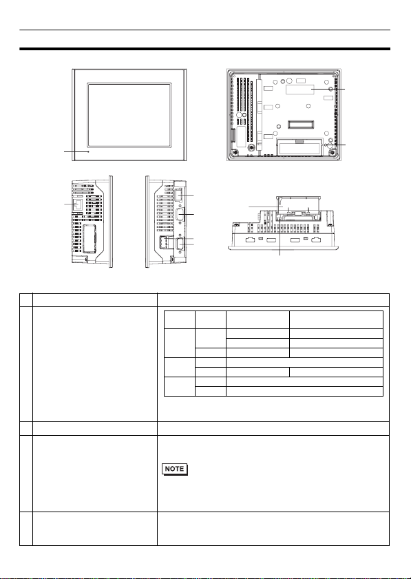
Part Names and Functions
Name Description
AStatusLED
B Expansion UnitInterface(EXT) Used to connect an expansion unit that can transmit data.
C CF Card Access LED
Lit in green when the CF Card is inserted and the cover
is closed, or when the CF Card is being accessed.
• Do not remove or insert the CF Card when the LED
lamp is on. Doing so may damage data on the CF
Card.
D Ethernet Interface (LAN) 10BASE-T/100BASE-TX
This interface uses an RJ-45 type modular jack
connector (8 pins).
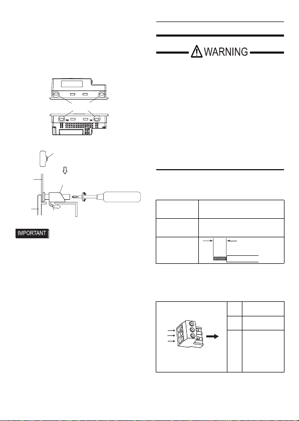
A
Front
DF
G
E
H
B
C
I
J
Rear
Right sideLeft side Bottom
Color Indicator
Operation Mode
(Drawing) Logic execution mode
(when logic is enabled)
Green ON OFFLINE
-
In operation RUN
Flashing
In operation STOP
Red ON When power is turned on.
Flashing
In operation Major Error
Orange ON Backlight burnout or GP malfuction *1
*1 When backlight replacement or repair of the GP is
required, please contact your local GP distributor.
Flashing
During software startup

3
E Power Connector (Socket)
-
F USB Host Interface (USB) Complies with USB 1.1. Uses a “TYPE-A” connector.
Power supply voltage:DC5V ±5%,
Output current:500mA (max.)
The maximum communication distance: 5m
G Serial Interface (COM1) D-sub 9-pin plug type. RS232C, RS422, and RS485
are switched by software.
H Serial Interface (COM2) D-sub 9-pin socket type. RS422 and RS485 are
supported.
ICFCardCover
J DIP Switches
Located inside the CF Card Cover.
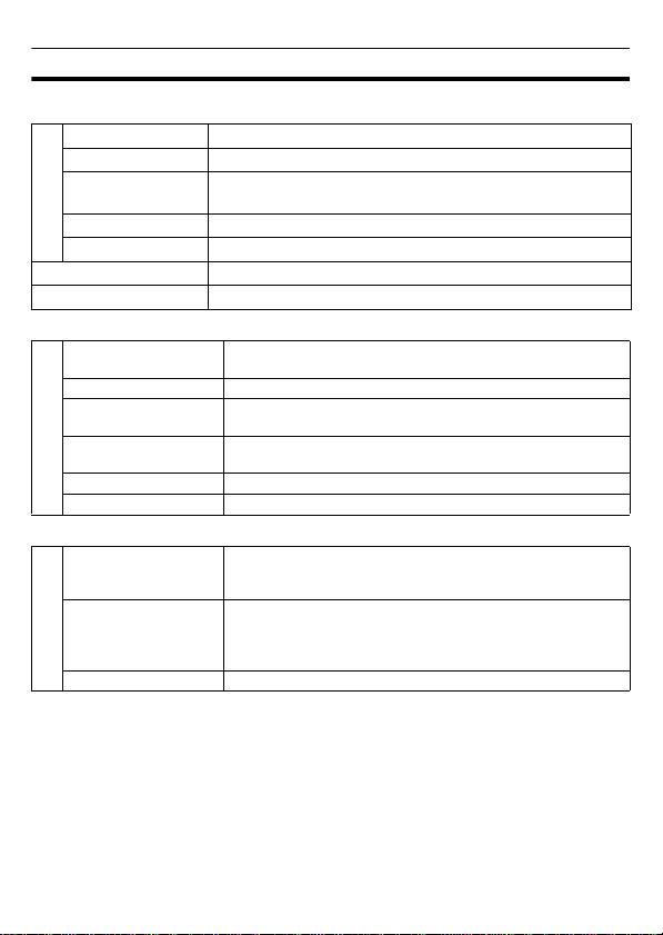
4
General Specifications
Electrical Specifications
Environmental Specifications
Structural Specifications
Power Supply
Input Voltage DC24V
Rated Voltage DC19.2 to 28.8V
Allowable Voltage
Drop 5ms (max.)
Power Consumption 26W (max.)
In-Rush Current 30A (max.)
Voltage Endurance
AC1000V 20mA for 1 minute (between charging and FG terminals)
Insulation Resistance DC500V 10MΩ(min.) (between charging and FG terminals)
Physical
Surrounding Air
Temperature 0 to 50°C
Storage Temperature -20 to +60°C
Ambient Humidity 10 to 90% RH (Wet bulb temperature: 39°C max. - no
condensation.)
Storage Humidity 10 to 90% RH (Wet bulb temperature: 39°C max. - no
condensation.)
Dust 0.1mg/m3and below (non-conductive levels)
Pollution Degree For use in Pollution Degree 2 environment.
Installation
Grounding Grounding resistance of 100Ω, 2mm2or thicker wire, or your
country’s applicable standard.
(Same for FG and SG terminals)
Structure*1
*1 The front face of the GP unit, installed in a solid panel, has been tested using conditions equivalent to
the standards shown in the specification. Even though the GP unit’s level of resistance is equivalent to
these standards, oils that should have no effect on the GP can possibly harm the unit. This can occur in
areas where either vaporized oils are present, or where low viscosity cutting oils are allowed to adhere
to the unit for long periods of time. If the GP’s front face protection sheet becomes peeled off, these
conditions can lead to the ingress of oil into the GP and separate protection measures are suggested.
Also, if non-approved oils are present, it may cause deformation or corrosion of the front panel’s plastic
cover. Therefore, prior to installing the GP be sure to confirm the type of conditions that will be present
in the GP’s operating environment.
If the installation gasket is used for a long period of time, or if the unit and its gasket are removed from
the panel, the original level of the protection cannot be guaranteed. To maintain the original protection
level, be sure to replace the installation gasket regularly.
Rating: IP65f NEMA #250 TYPE 1
(Front surface at panel embedding)
Feature size: All-in-one
Installation configuration: Panel embedding
Cooling Method Natural air circulation
5
External Interfaces
• For instructions on how to connect to other devices, always refer to the “GP-Pro EX
Device/PLC Connection Manual”.
• Always connect the #5 SG (Signal Ground) of the GP unit to the connected device,
especially if the connected device is also not isolated. Failure to do so may damage
the RS232C/RS422/RS485 circuit.
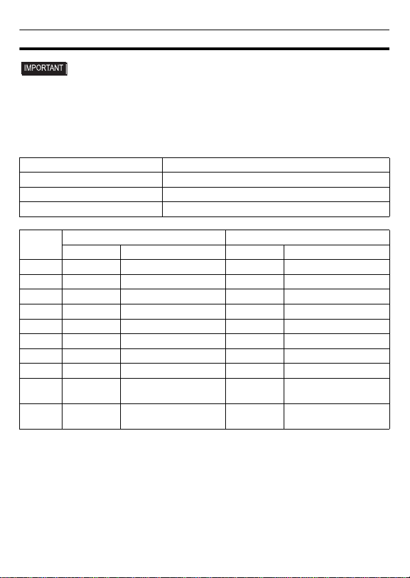
COM1
Recommended Cable Connector XM2D-0901 <made by OMRON Corp.>
Recommended Jack Screw XM2Z-0073 <made by OMRON Corp.>
Recommended Cable Cover XM2S-0913 <made by OMRON Corp.>
Fitting fastener #4-40 (UNC)
Pin # RS232C RS422/RS485
Signal Name Meaning Signal Name Meaning
1 CD Carrier Detect RDA Receive Data A(+)
2 RD(RXD) Receive Data RDB Receive Data B(-)
3 SD(TXD) Send Data SDA Send Data A(+)
4 ER(DTR) Data Terminal Ready ERA Data Terminal Ready A(+)
5 SG Signal Ground SG Signal Ground
6 DR(DSR) Data Set Ready CSB Clear to Send B(-)
7 RS(RTS) Request to Send SDB Send Data B(-)
8 CS(CTS) Clear to Send CSA Clear to Send A(+)
9CI(RI)/VCC
Called status display/
+5V ±5% Output 0.25A
*1
*1 The RI/VCC selection for Pin #9 is switched via software. The VCC output is not protected against
overcurrent. To prevent damage or unit malfunctions, use only the rated current.
ERB Data Terminal Ready B(-)
Shell FG Frame Ground
(Common with SG) FG Frame Ground
(Common with SG)
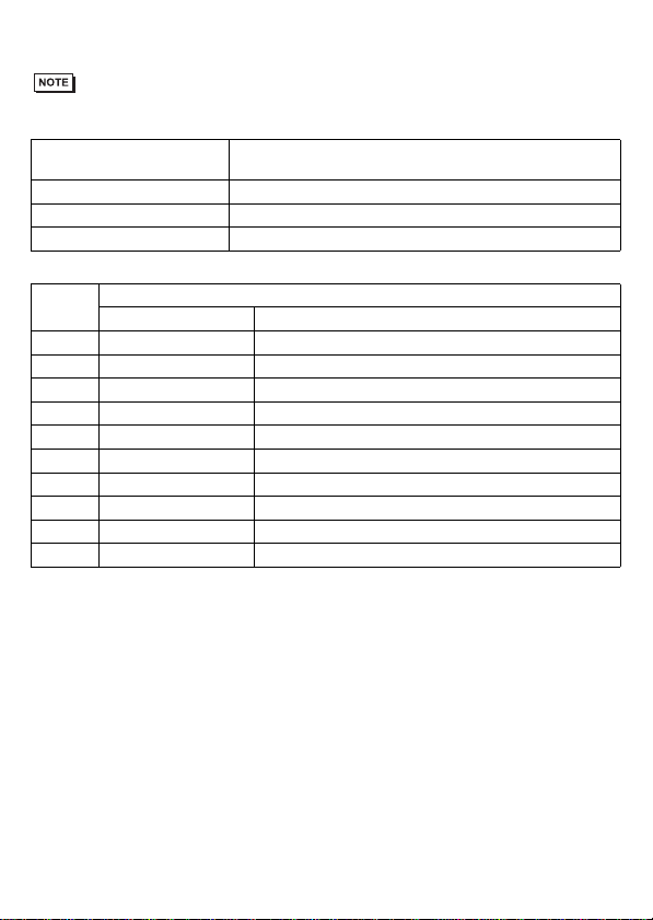
6
COM2
• Always connect close to the GP unit's COM port when terminating with the
termination pins (TRMRX/TRMTX).
Recommended Cable
Connector XM2A-0901 <made by OMRON Corp.>
Recommended Jack Screw XM2Z-0073 <made by OMRON Corp.>
Recommended Cable Cover XM2S-0913 <made by OMRON Corp.>
Fitting fastener #4-40 (UNC)
Pin # RS422/RS485
Signal Name Meaning
1 TRMRX Termination (Receiver side: 100Ω)
2 RDA Receive Data A(+)
3 SDA Send Data A(+)
4 RS(RTS) Request for Send
5 SG Signal Ground
6VCC
+5V ±5% Output 0.25A
*1
*1 The VCC output for Pin #6 is not protected against overcurrent. To prevent damage or unit
malfunctions, use only the rated current.
7 RDB Receive Data B(-)
8 SDB Send Data B(-)
9 TRMTX Termination (Receiver side: 100Ω)
Shell FG Frame Ground (Common with SG)

7
Installations
1. Installation Requirements
• For easier maintenance, operation, and
improved ventilation, be sure to install the
GP at least 100mm [3.94in.] away from
adjacent structures and other equipment.
• Be sure that the surrounding air
temperature and the ambient humidity
are within their designated ranges.
(Surrounding air temperature: 0 to
50°C, Ambient humidity: 10 to 90%RH,
Wet bulb temperature: 39°C max.)
When installing the GP on the panel of
a cabinet or enclosure, “Surrounding
air temperature” indicates both the
panel face and cabinet or enclosure’s
internal temperature.
• Be sure that heat from surrounding
equipment does not cause the GP to
exceed its standard operating
temperature.
2. GP Installation
(1) Create a Panel Cut and insert the GP
into the panel from the front. Deter-
mine the panel thickness according to
the panel thickness range with due
consideration of panel strength.
(2) Confirm that the installation gasket is
attached to the GP unit and then
place the GP unit into the Panel from
the front.
• It is strongly recommended that you
use the installation gasket, since it
absorbs vibration in addition to
repelling water.
For the procedure for replacing the
installation gasket, refer to “GP3000
Series Hardware Manual”.
100
[3.94]
100
[3.94]
100
[3.94] 100
[3.94]
Unit:mm[in.]
100
[3.94]
100
[3.94]
100
[3.94]
Panel Face Inside Cabinet
GP X Y Panel
thickness
AGP-3300 U
156.0
[6.14 ]
123.5
[4.86 ]
1.6 [0.06]
to
5.0 [0.20]
Unit: mm [in.] Xr ≤ 3 [0.12]
Panel
thickness
GP
Y
+1
-0
+0.04
-0
+1
-0
+0.04
-0
8
(3) The following figures show the four
(4) fastener insertion slot locations.
Insert each fastener’s hook into the
slot and tighten it with a screwdriver.
Insert the installation fasteners
securely into the insertion slot
recess.
• Tightening the screws with too much force
can damage the GP unit’s plastic case.
• The necessary torque is 0.5N•m.
Wiring
• To avoid an electric shock, prior to con-
necting the GP unit’s power cord termi-
nals to the power terminal block,
confirm thatthe GP unit’s power supply
is completely turned OFF, via a
breaker, or similar unit.
• Any other power level can damage
both the GP and the power supply.
• When the FG terminal is connected, be
sure the wire is grounded.
1. Wiring the DC Type Power Cord
Power Cord Specifications
Use copper conductors only.
Power Connector (Plug) Specifications
Top
Insertion Slots
Bottom
Insertion Slot Recess
Hook the fastener on the
Recess,
Panel Installation Fastener
GP Hook
and secure the fastener
on the panel with a
screwdriver.
Power Cord
Diameter 0.75 to 2.5mm2
(18 - 12AWG)
Conductor
Type Simple or Stranded Wire*1
*1 If the Conductor’s end (individual) wires are not
twisted correctly, the end wires may either short
against each other, or against an electrode.
Conductor
Length
+ 24V
-
0V
FG
Grounding
Terminal
connected
to the GP
chassis
7mm
[0.28in]
Insertion
Direction
+
-
FG

9
• The power connector (plug) is CA5-
DCCNM-01 made by Pro-face or
MSTB2,5/3-ST-5,08 made by Phoenix
Contact.
When connecting the Power Cord, use the
following items when performing wiring:
(Items are made by Phoenix Contact.)
Connecting the GP Power Cord
(1) Confirm that the GP unit’s Power
Cord is unplugged from the power
supply.
(2) Remove the power connector (plug)
from the right side of the main unit.
(3) Strip the power cord, twist the
conductor’s wire ends, insert them
into the pin terminal and crimp the
terminal. Attach the terminal to the
power connector.
• Use a flat-blade screwdriver (Size 0.6
X 3.5) to tighten the terminal screws.
The torque required to tighten these
screws is 0.5 to 0.6N•m [5-7Lb•In.].
• Do not solder the cable connection.
Doing so may damage the unit due to
abnormal heat or cause a fire.
(4) Attach the Power connector (Plug) to
the GP.
2. Power Supply Cautions
• Input and Output signal lines must be
separated from the power control
cables for operational circuits.
• To improve noise resistance, be sure to
twist the ends of the power cord wires
before connecting them to the Power
connector (Plug).
• The GP unit’s power supply cord should
not be bundled with or kept close to main
circuit lines (high voltage, high current),
or input/output signal lines.
• To reduce noise, make the power cord
as short as possible.
• If the supplied voltage exceeds the GP
unit’s range, connect a voltage trans-
former.
• Be sure to use a low noise power
supply between the line and the
ground. If there is an excess amount of
noise, connect a noise reducing
transformer.
• The temperature rating of field installed
conductors: 75oC only.
• Use voltage and noise reducing
transformers with capacities exceeding
Power Consumption value.
• Must be used with a Class 2 Power
Supply. (24VDC)
Recomended
Driver SZF 1-0.6x3.5
(1204517)
Recomended
Pin Terminals
AI 0.75-8GY (3200519)
AI 1-8RD (3200030)
AI 1.5-8BK (3200043)
AI 2.5-8BU (3200522)
Recomended
Pin Terminal
Crimp Tool
CRIMPFOX ZA 3
(1201882)
Power Connector (Socket)
Power connector (Plug)
FG
+
-
10
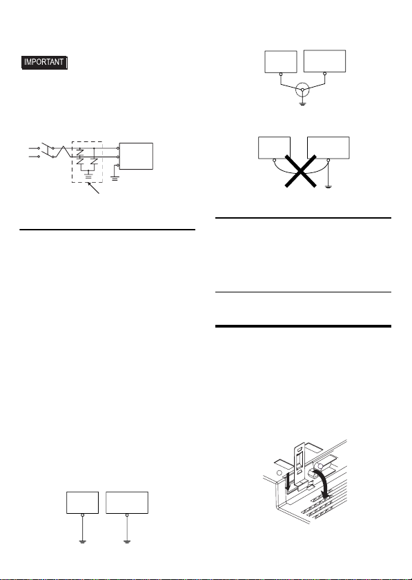
• Connect a surge absorber to handle
power surges.
• Be sure to ground the surge absorber
(E1) separately from the GP unit (E2).
Select a surge absorber that has a
maximum circuit voltage greater then
that of the peak voltage of the power
supply.
3. Grounding Cautions
• Be sure to create an exclusive ground
for the Power Cord’s FG terminal. Use
a grounding resistance of 100Ω, a wire
of 2mm2or thicker, or your country’s
applicable standard.
• The SG (signal ground) and FG (frame
ground) terminals are connected
internally in the GP unit.
When connecting the SG line to
another device, be sure that the design
of the system/connection does not
produce a shorting loop.
• The grounding wire should have a
cross sectional area greater then
2mm2. Create the connection point as
close to the GP unit as possible, and
make the wire as short as possible.
When using a long grounding wire,
replace the thin wire with a thicker
wire, and place it in a duct.
4. Input/Output Signal Line Cautions
• All GP Input and Output signal lines
must be separated from all operating
circuit (power) cables.
• If this is not possible, use a shielded
cable and ground the shield.
Securing the USB cable
connection
When using a USB device, attaching the
USB holder to the USB Interface located
on the side of the GP unit prevents the
USB cable Interface from becoming
disconnected.
Attaching the USB Cable Clamp
(1) Insert the USB holder into the slot in
front of the GP unit’s USB port and
pull it down and forward.
Lightening Surge Absorber
E1 E2
FG GP
GP unit Other
Equipment
Exclusive Grounding
(BEST)
GP unit Other
Equipment
Common Grounding (OK)
GP unit Other
Equipment
Common Grounding
(Not OK)
12

11
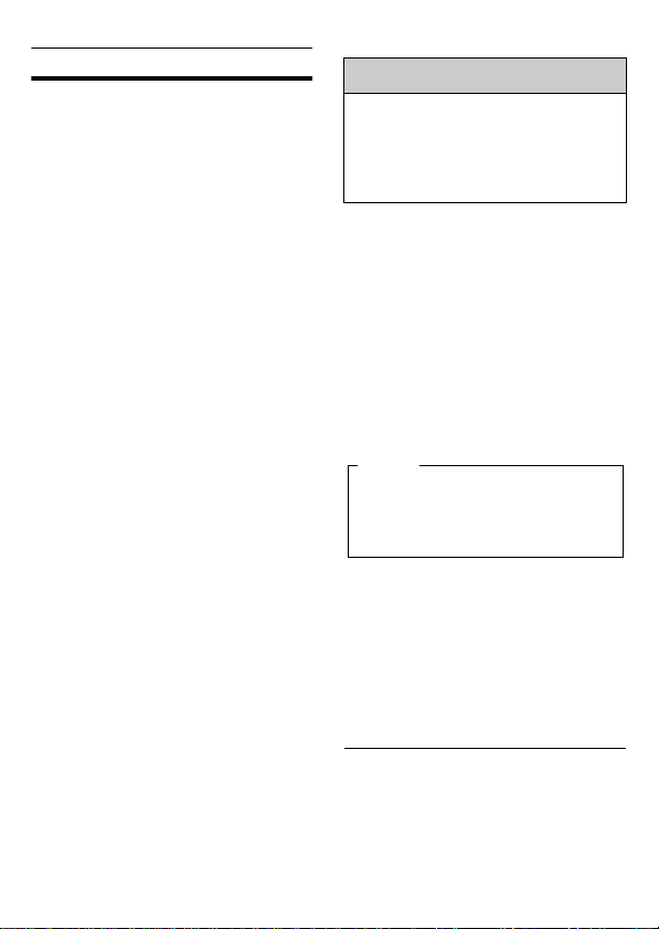
(2)
Pass the band of the USB cable clamp
through the bridge of the USB holder.
(3) Insert the USB cable into the port.
Fasten the band around the plug and
secure it with the clamp.
Removing the USB Cable Clamp
(1) Lower the tab and lift the clamp to
release the plug.
UL/c-UL Approval
The AGP3300-U1-D24 unit is a UL/c-UL
listed product.
(UL File No.E220851)
These products conform to the following
standards:
• UL508
Industrial Control Equipment
•
CSA-C22.2 No.142-M1987 (c-UL Approval)
Process Control Equipment
<Cautions>
Be aware of the following items when
building the GP into an end-use product:
•
The GP unit’s rear face is not approved as
an enclosure. When building the GP unit
into an end-use product, be sure to use an
enclosure that satisfies standards as the
end-use product’s overall enclosure.
• The GP unit must be used indoors only.
• Install and operate the GP with its front
panel facing outwards.
• If the GP is mounted so as to cool itself
naturally, be sure to install it in a
vertical panel. Also, it’s recommended
that the GP should be mounted at least
100mm away from any other adjacent
structures or machine parts. The
temperature must be checked on the
final product in which the GP is
installed.
• For use on a flat surface of a Type 1
Enclosure.
USB Holder
Bridge
USB Holder
Clamp
USB Cable
Tab
Clamp
Product Model No.
UL/c-UL Registration
Model No.
AGP3300-U1-D24 3710015-01
12
CE Marking
• The AGP3300-U1-D24 unit is a CE
marked, EMC compliant product.
This unit also conforms to EN55011
Class A, EN61000-6-2 directives.
Digital Electronics Corporation
8-2-52 Nanko-higashi
Suminoe-ku, Osaka 559-0031
JAPAN
TEL: +81-(0)6-6613-3116
FAX: +81-(0)6-6613-5888
http://www.pro-face.com
The information in this document is
subject to change without notice.
© Copyright 2009 Digital Electronics
Corporation. All rights reserved.
PFX119872F
.AGP3300-U1-MT02E-BTH
2010.6 SS/B
Inquiry
Do you have any questions about
difficulties with your GP?
Please access our site anytime that
you need help with a solution.
http://www.pro-face.com/otasuke/
Please be aware that Digital Electronics
Corporation shall not be held liable by the
user for any damages, losses, or third
party claims arising from the uses of this
product.
Note
Table of contents
Other Pro-face Control Panel manuals

Pro-face
Pro-face Pro-face ST Series User manual

Pro-face
Pro-face GLC2500-TC41-200V User manual

Pro-face
Pro-face GP-3500 Series User manual

Pro-face
Pro-face GP3000U Series User manual

Pro-face
Pro-face GLC2500-TC41-24V User manual

Pro-face
Pro-face GC4000 Series User manual

Pro-face
Pro-face GP-4100 series User manual

Pro-face
Pro-face GP-2300 Series User manual
Popular Control Panel manuals by other brands

Airmax
Airmax 651730 installation instructions

mr. steam
mr. steam iSteam Controls Installation, operation & maintenance manual

Securakey
Securakey SK-ACP Connecting guide

SIGMA TEK
SIGMA TEK ETV 0853-3 manual

DM TECH
DM TECH FP9000E Installation and operation manual

BENSON HEATING
BENSON HEATING CP2 User handbook


