EL iconnect User manual

User Manual
For quick installation information please refer to the iConnect
Quick Start Installation Guide provided on our website: www.electronics-line.com

Quick Reference Guide
Function Press… Additional Information
ARM
FULL PART PERIMETER
If One-Key Arming is disabled
on the Control System, enter
your user code when arming.
The default Master code is
1234.
INSTANT
ARM
Hold down this key until
“Instant Arming OK?” is
displayed. Then Press ¥.
Instant arming cancels the
entry delay after Part or
Perimeter arming. This
feature can be enabled by
your installer.
DISARM [USER CODE] Entering your user code also
silences the siren in the event
of an alarm.
PANIC
ALARM
+
Press these keys together and
hold them down to generate
an alarm.
FIRE
ALARM
+
MEDICAL
ALARM
+
MENU MODE then [USER CODE] Use the menu navigation keys
(/) until the required
menu item is displayed then
press ¥. Alternatively, enter
the shortcut (e.g. 21 for
Bypass Zones).
CHECK
TROUBLE
CONDITIONS Use this key scroll the
system trouble list Pressing also silences any
trouble tones that may be
sounded by the system.
SWITCH
HA/PGM
UNIT ON then [HA/PGM UNIT #]
Enter the HA module number
in two digits
(e.g. 03, or 30/31 for PGM).
SWITCH
HA/PGM
UNIT OFF then [HA/PGM UNIT #]
SERVICE
CALL Hold down this key until
“Service Call Dialing” is
displayed. The number dialed
for the service call is
programmed by your
installer.
GLOBAL
CHIME then Use the menu navigation
keys (/) to choose enable
or disable, then press ¥.
RECORD
MESSAGE then After recording a message,
“Message Waiting” is
displayed until the message
is played back.
OR OR

-3-
Function Press… Additional Information
PLAY
MESSAGE then The Message Center is an
optional feature that is
included with certain versions
of iConnect Control
System.
Telecontrol Commands
Function Press… Function Press…
2-WAY AUDIO DISARM
FULL ARM SIREN
CANCEL
HA/PGM
UNIT XX ON*then EXTEND CALL
HA/PGM
UNIT XX OFF* then DISCONNECT then
*for PGM XX=30/31

-4-
Table of Contents
Quick Reference Guide .....................................................................................................................2
Table of Contents ..............................................................................................................................4
1. Introduction and Overview......................................................................................................6
1.1. Documentation Conventions ..............................................................................................6
1.2. Security System Components............................................................................................7
1.3. System Monitoring .............................................................................................................8
1.4. Home Automation..............................................................................................................8
1.5. Self-Monitoring...................................................................................................................8
1.6. Telephone Control..............................................................................................................8
1.7. Vocal Message Annunciation.............................................................................................9
1.8. Web/Smartphone Access...................................................................................................9
2. The User Interface..................................................................................................................10
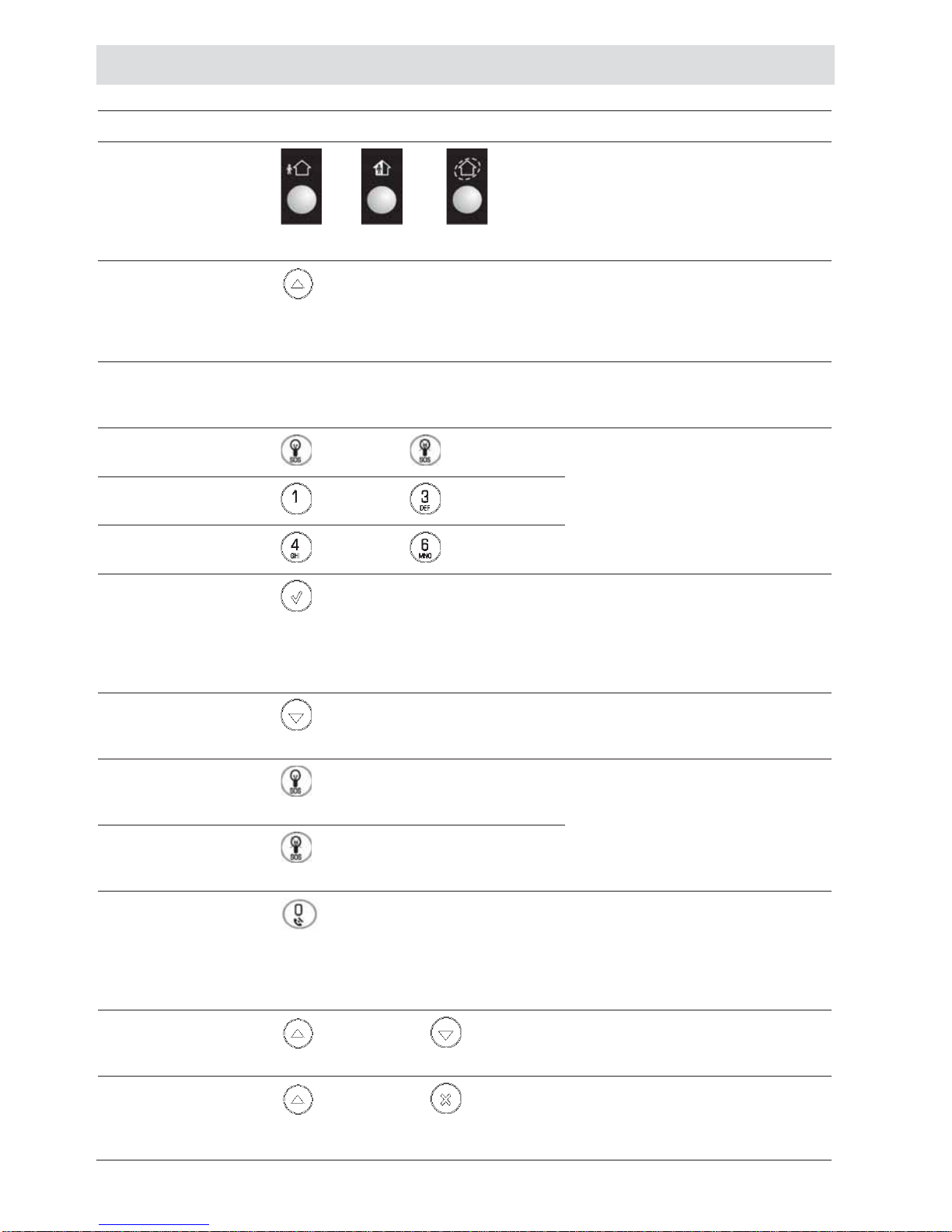
2.1. Front Panel ......................................................................................................................10
2.2. Alarm Sounding Patterns .................................................................................................12
2.3. Keyfobs............................................................................................................................12
2.4. Wireless Keypads............................................................................................................12
3. Arming and Disarming...........................................................................................................15
3.1. Arming Modes..................................................................................................................15
3.2. Arming the System...........................................................................................................15
3.3. Disarming the System......................................................................................................17
3.4. Arm Status Indication and Other System Status Indication.............................................. 17
3.5. Arming and System Tones...............................................................................................18
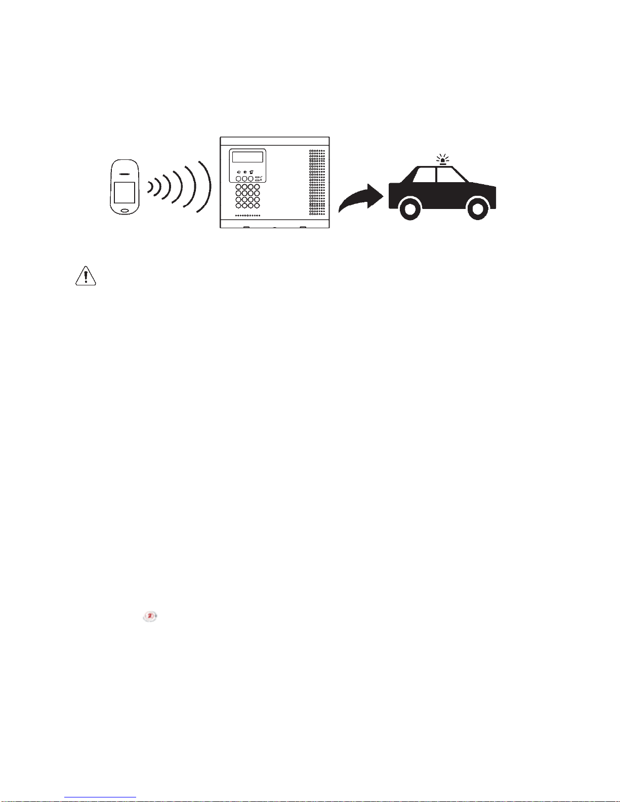
3.6. Remote Arming and Disarming........................................................................................19
4. Web User Application ............................................................................................................21
4.1. Register to MyELAS.........................................................................................................21
4.2. Login to MyELAS .............................................................................................................22
4.3. The Main Page.................................................................................................................23
4.4. Arming and Disarming......................................................................................................26
4.5. Web Application Settings.................................................................................................27
4.6. Event Log History.............................................................................................................36
4.7. Home Automation............................................................................................................ 37
4.8. Video Verification............................................................................................................. 38
5. Panic Alarms ..........................................................................................................................41
5.1. Keypad Alarms.................................................................................................................41
5.2. Keyfob Panic Alarm..........................................................................................................41
5.3. Medical/Panic Alarm ........................................................................................................41
6. Home Automation and PGM.................................................................................................. 42
6.1. Keypad Control ................................................................................................................42
6.2. Keyfob Control .................................................................................................................43
6.3. Telephone Control............................................................................................................43
6.4. SMS Control.....................................................................................................................43
6.5. Scheduling (not relevant to PGM).....................................................................................44
7. Telecontrol..............................................................................................................................45
7.1. Calling your Home............................................................................................................45
7.2. Service Call......................................................................................................................47
7.3. Two-Way Audio after an Alarm ........................................................................................47
7.4. Two-Way Audio Follow-Me...............................................................................................47

-5-
7.5. Simplex Mode ..................................................................................................................47
8. Advanced System Operation................................................................................................. 48
8.1. Cancel Report..................................................................................................................49
8.2. Zone Bypassing/Unbypassing.......................................................................................... 49
8.3. User Codes......................................................................................................................50
8.4. Follow-Me ........................................................................................................................52
8.5. Event Log.........................................................................................................................52
8.6. Service Menu...................................................................................................................53
Appendix A: Menu Structure...........................................................................................................59
Appendix B: Glossary...................................................................................................................... 60

-6-
1. Introduction and Overview
This user manual explains all you need to know about your iConnect security system
and provides step-by-step instructions for all the system’s user functions. In addition to
the explanation you will receive from your installer, we urge you to read this manual so
that you can take full advantage of your system’s features. Keep this manual in an
accessible location for future reference.
The iConnect system has many features in order to suit a wide range of applications.
This manual outlines all of these features but it is likely that there are options that are
not relevant to your system. If you have any questions regarding the availability of the
features described in the manual, please ask your installer.
1.1. Documentation Conventions
In order to simplify the procedures that appear in the rest of this manual, the following
conventions are used:
Item… Description…
Select… Use the arrow buttons to scroll through the options and
press ¥.
From the Event
Log Menu, select
Clear Log.
Enter the main menu by pressing ¥and entering your
user code. Using the arrow buttons, navigate until you
reach Event Log and press ¥. Using the arrow buttons,
navigate until you reach Clear Log and press ¥.
From the Service
menu, select Set
Time/Date, Set
Date.
The same as above only this time you are navigating
through three menu levels.
[7012] The shortcut to a specific menu item from the main menu.
In this case, this is the shortcut for Set Date. These
appear in the procedures as an additional aid to menu
navigation.
[#5] A shortcut to a specific item in a sub-menu. For example,
[#5] is the shortcut to Bell enable disable in the sub-
menu that is opened once you have selected the detector
you want to program.
¥, abuttons Indicate buttons that appear on the keypad ( , )
5. Interface Test The text that actually appears on the LCD display (italics).
Note
Important caution, please pay attention.

-7-
1.2. Security System Components
Your security system is made up of a Control System, various detectors and a number of
optional peripheral devices. This section explains the role of each component in your
system.
Control System
The Control System is the brain of the system. It
communicates with all the devices connected to the
system. For example, in the event of a burglary, a
detector sends a signal to the Control System
indicating that it has sensed motion on the premises.
On receiving this signal, the Control System makes
the decision to report the alarm to your monitoring
service and activate the siren.
Detectors
Detectors are the devices that protect your home, alerting the
Control System when there is a breach in security. Magnetic
contacts protect your doors and windows while motion detectors
with built-in image capture modules are able to detect an intruder
moving across its field of view and snap an instant image as proof
of intrusion. Additionally, smoke, carbon monoxide, gas leak and
flood detectors can be installed to provide an early warning in the
event of a fire, the presence of dangerous gases or the potential for
flooding.
Keyfobs
Keyfobs are hand-held transmitters that are used to operate the
system. Various keyfobs are available providing a number of
functions. For example, arming/disarming the system, sending
medical and panic alarms and various home automation functions.
Keypads
The keypads enable you to communicate with the Control System
in order to perform a number of different functions. The main
function you can perform using a keypad is to arm the system
when leaving your home and to disarm on your return.
Sirens and Strobes
While the Control System includes a built-in internal siren, it is
possible that you also have an external siren and strobes installed.
The sirens are sounded and the strobes are activated during certain
alarm conditions serving to warn you and ward off intruders.

-8-
1.3. System Monitoring
When an event occurs within the system, the Control System sends a message to your
monitoring service describing the exact nature of the event. This enables the monitoring
service to take the required action. System monitoring can implement either regular
telephone or cellular communication.
Remember that no security system can prevent emergencies. This system is only intended
to alert you in case of an emergency and should not take the place of prudent security
practices or life and property insurance.
1.4. Home Automation
An optional expansion module can provide you with the ability to control up to 16
individual electrical appliances or lights using the front panel keypad, wireless keypads
or keyfobs. Additionally, each appliance can be programmed to be turned on and off
automatically according to various schedules and system status conditions.
1.5. Self-Monitoring
In addition to the ability to report to a monitoring service, the system can also send you
and other users notification when an event occurs. This may be in the form of vocal
messages played over the telephone or, if your system supports cellular communication,
you can receive information on system status via SMS. If an alarm occurs on the
premises, you are informed no matter where you are in the world.
1.6. Telephone Control
DTMF Telecontrol
The iConnect offers a range of “Telecontrol” features that provide remote access via
the telephone. These features include remote arming/disarming, HA on/off, PGM output
activation/deactivation, siren cancel and Two-Way audio via the Control System’s built-
in microphone and speaker -- see Telecontrol.
The Two-Way Audio features allow you to contact your home directly in the event of an
alarm or simply to check the premises when you are away.
A detector detects. The Control System is alerted. An alarm is generated and the
monitoring service is notified.

-9-
SMS Control
Using your cellular phone, you can also send commands to the appliances controlled by
the Home Automation feature using SMS and receive confirmation when the command
is received.
1.7. Vocal Message Annunciation
Vocal message annunciation is an optional feature that, if enabled in programming,
causes the system to play short messages that indicate system status.
1.8. Web/Smartphone Access
The Web/Smartphone application provides an interface to your security system from
your Internet browser or Smartphone. You can perform a wide range of tasks such as
arm/disarm, zone bypass, user code management and home automation control.
Additionally, you can set up the contacts for whom you wish to be alerted (by email or
text message) when selected events occur.
The Web/Smartphone application also allows you to check your home at any time either
by viewing the history of recent events that have occurred or by viewing video
snapshots from PIR cameras installed on the premises. For further information, see Web
User Application

-10-
2. The User Interface
There are several methods you can use to operate the system. Apart from the keypad on
the front panel, your system may include a number of peripheral devices such as
keypads and keyfobs.
This chapter provides a brief introduction to each of the devices you can use to operate
the system. It is important that you familiarize yourself with these devices before
reading the following chapters that shall describe system operation in further detail.
The front panel is the main user interface that provides you with all the functions you
need to control your security system. iConnect Control System is available with the
LCD front panel configuration.
2.1. Front Panel
LCD Front Panel display and LEDs inform you of system arming status, power failures,
and system trouble conditions. Its alphanumeric keypad enables you to enter your user
code when arming and disarming, and to silence the siren in the event of an alarm.
Arming Keys
Three arming keys are available: Full, Part, and Perimeter. These keys arm the system
using one of the three arming methods. One-key Arming is an option that is
programmed by your installer. If this option is disabled, you must also enter a user code
when arming.
System
Status
indicators
LCD
Display
Arming
Keys
Alpha-
numeric
Keypad
Menu
Navigation
Keys
Home
Automation/
PGM Keys

-11-
Service Call Button
The Service Call button enables you to contact the monitoring service and talk to an
operator.
To initiate a service call, press and hold down the Service Call key for a few
seconds.
Vocal Message Recording and Playback
LCD front panel allows you to record a short message that may be played back later by
another user -- see Service Menu, Message Center.
PGM and Home Automation On/Off Keys
Pressing one of the Home Automation keys ( ON, OFF) followed by the unit
number (01-16, or 30, 31 for PGM) enables you to control lights and appliances in your
home, activate and deactivate the PGM output.
Pressing both Home Automation keys simultaneously generates an SOS panic alarm.
System Status LEDs
The System Status indicators provide essential information on the status of the system
such as arm, disarm, alarm and power failure conditions.
If the OK LED is… It means…
Off Both AC and Battery power are disconnected.
On – Green System Power status is OK and there is no System Trouble.
Flashing Green Open Zone. Check that the windows and doors are closed
and no movement is detected by the detectors within the
protected area).
On – Yellow System Trouble.
Flashing Yellow (slow) Battery low from the Control System or transmitters.
Flashing Yellow (fast) AC loss.
Intermittent On/Off – Yellow System Trouble in addition to AC loss/Low Battery.
If the Arm Status LED
is…
It means…
Off The system is disarmed.
On – Green The system is armed.
Flashing Red An alarm has occurred. Alarm indication is cleared the
next time you arm the system or view the relevant event
in the event log.
Alarm indication is not displayed after a silent panic alarm.

-12-
System Trouble Indication
In the event that the system detects a trouble condition, “System Trouble” appears on
the display. To identify the problem, scroll through the trouble list by pressing.
Scrolling the trouble list also silences system trouble tones that may be sounded if
enabled in programming. When the trouble condition is restored, it is removed from the
system trouble list. For detailed information on system messages, see Arm Status
Indication.
2.2. Alarm Sounding Patterns
The following table summarizes various alarms sounded by the control system.
Alarm Alarm Sounding Pattern Description
Burglary ON (continuously)
Fire ON - ON - ON, 1.5-second pause, ON - ON – ON......
Gas ON - ON - ON - ON (short bursts), 5 second pause, ON - ON - ON -
ON......
Medical ON (continuously) – only applicable for Medical alarm from zone
Flood 4 rapid tones sounded once per minute (same as Trouble tones)
Environmental 4 rapid tones sounded once per minute (same as Trouble tones)
2.3. Keyfobs
The iConnect supports two types of keyfob transmitter (EL-4714, EL-4711M/P). The
functions of the buttons on each keyfob are shown below.
EL-4714
EL-4711M/P
2.4. Wireless Keypads
The system supports up to four Wireless Keypads. The Wireless Keypad (EL-4727) is an
intelligent two-way wireless keypad with LCD display. Apart from serving as an
additional arming station, the Wireless Keypad provides memo recording options,
control over up to 16 home automation devices, and panic alarm function. You can arm
and disarm the system using the Smartkey (if supported).
Medical/Panic
Emergency
Perimeter Arm
or Home
Automation/PGM
Part Arm
or Home
Automation/PGM
Full Arm Disarm

-13-
nSpeaker
oLCD Display
pArming Keys
qKeypad
rMicrophone (optional)
sSystem Status LEDs
Wireless Keypad (EL-4727)
Numeric Keypad
The numeric keypad allows you to arm or disarm the system by entering a user code.
Arming Keys
Three arming keys (Full, Part and Perimeter) allow you to arm the system using one of
the three arming methods – see Arming and Disarming. One-key Arming is an option
that is programmed by your installer. If this option is disabled, you must also enter a
user code when arming.
Panic Alarm
Simultaneously pressing the Full and Perimeter buttons generates a panic alarm.
PGM/Home Automation On/Off Keys
Pressing one of the Home Automation keys followed by the unit number (01-16) enables
you to control lights and appliances in your home.
To generate a panic alarm, press both Home Automation keys simultaneously and hold
them down
Cancel
The Cancel key clears the keypad in the event that you pressed a key by mistake.
For example, when entering your code you enter a wrong digit; the system waits for you
to enter all four digits before it decides that the code is incorrect. Pressing the Cancel key
causes the keypad to disregard what was previously entered enabling you to start again.

-14-
LEDs
Two status LEDs (OK and ) indicate arming and power status of the system:
If the OK LED is… It means…
Off The system is disconnected from all power sources.
On - Green The keypad is powered by AC and the battery is not low.
Flashing Yellow (slow) Local backup battery low.
Flashing Yellow (fast) Wireless Keypad AC loss.
If the LED is… It means…
Off The system is disarmed.
On - Green The system is armed.
Flashing Red An alarm has occurred. This alarm indication is reset when
the system is armed using any of the three arming
methods.
Alarm indication is not displayed after a silent panic alarm.

-15-
3. Arming and Disarming
Arming can be defined as activating the system. When the system is armed, it monitors
the zones that are protected by the detectors. If a detector detects an intrusion, the
system generates an alarm.
3.1. Arming Modes
Three arming modes are available: Full, Part and Perimeter. These modes enable you to
arm your system accordingly to suit different circumstances.
Full Arming
Part Arming
Perimeter Arming
Full arming activates the entire
system. This arming method is
used when you intend to leave
your home, leaving the
premises empty.
Part arming enables you to
arm a section of your home
while remaining on a different
part of the premises.
Perimeter arming enables you
to activate the perimeter zones
(the windows and doors of
your home) enabling you to
move freely within the
protected area.
Certain detectors, such as smoke, carbon monoxide, gas and flood detectors, are always
active regardless of system status.
3.2. Arming the System
Before arming the system, check that all doors and windows are secured so that the
system is ready for arming.
If the One-key Arming option is disabled in programming, you must enter your
user code when arming the system from a keypad.
Arming with the Front Panel or Wireless Keypad
To arm the system using the front panel or Wireless Keypad:
xPress one of the three arming keys; the exit delay begins to count
down. At the end of the exit delay, the system is armed.
If the One-key Arming option is disabled in programming, you must
enter your user code when arming the system from a Wireless
Keypad, or place a registered smartkey (if supported) against the
center of the smartkey reader.

-16-
Arming with the Keyfob
To arm the system using the keyfob:
xPress the relevant button on your keyfob (see Keyfobs); the exit delay
begins to count down. At the end of the exit delay, the system
is armed.
Arming with the Key Switch
To arm the system using a key switch:
xOpen/close the key switch accordingly.
Forced Arming
Forced arming enables you to arm when the system is not ready. For example, if a door
protected by a magnetic contact is open, you may arm the system on condition that the
door will be closed by the end of the Exit delay. If the door is still open after the exit
delay expires, an alarm is generated.
Forced arming is available only if the option is enabled in programming. Forced arming
may be enabled for specific zones or for the entire system.
Instant Arming
Instant arming is a feature that allows you to cancel the entry delay after Part or
Perimeter arming the system. For this feature to function, it must be enabled in
programming by your installer.
To instantly arm the system.
1. Check if the system is ready to arm.
2. Press the Part or Perimeter arming key on the keypad and enter your user
code if One-Key Arming is disabled.
3. Press and hold down on your keypad until the message Instant Arming,
OK? is displayed
4. Press dž; the entry delay for the current arming period is canceled.
Supervised Arm
Supervised Arm is an optional feature designed to supervise intrusion detector activity
before you arm the system.
If supervised arm is enabled in programming and the system has not received a
transmission from a detector for a certain amount of time, all arming methods that
include that detector shall not be available.
In this case, press to check which detector is causing the “System Not Ready”
condition.
To make the required arming method available, activate the detector. If activating the
detector does not help, there may be a problem with the detector. You can bypass the
faulty detector’s zone to allow system arming until the problem is remedied – see Zone
Bypassing/Unbypassing.

-17-
3.3. Disarming the System
When you enter the premises, the entry delay begins to count down. You must disarm
the system within the entry delay time to prevent the system from triggering an alarm.
To disarm the system using a keypad:
xEnter your user code.
To disarm the system using a keyfob:
xPress the disarm button – see Keyfobs
To disarm the system using a key switch:
xOpen/close the key switch accordingly.
To disarm the System using a Smartkey (if supported):
xPlace a registered smartkey against the
center of the smartkey reader of the
Wireless Keypad. When the smartkey is read, the keypad will sound a
beep – the system is disarmed.
3.4. Arm Status Indication and Other System
Status Indication
The system’s arm status is displayed on the front
panel only. The following table explains the
various arm status descriptions that appear on
the LCD display.
Status Means…
DISARMED The system is disarmed.
FULL ARMED
The system has been armed using the displayed arming method.
PART ARMED
PERIMETER ARMED
FULL ARMING The system is in the process of arming (displayed during exit
delay).
PART ARMING
PERIMETER ARMING
PART ARMED INST The system has been armed using the displayed arming method
with the Instant arm feature activated.
PERIM ARMED INST
PART ARMING INST The system is in the process of arming with the Instant arm
feature activated.
PERI ARMING INST
The system may be programmed to display arm status at all times or only for the first
two minutes or 30 seconds after you arm or disarm the system according to the system's
configuration as programmed by the installer.
DISARMED
12:22:12

-18-
In addition to arm status, the system displays further status messages on the front
panel’s display. The following table explains common status indication messages that
may prevent you from arming your system.
Status Means…
ZONES IN ALARM Zones have been violated.
TAMPER ALARM The system has been tampered with.
SYSTEM NOT READY The system is not ready to arm, check that all doors and windows
are closed.
KEYPAD LOCKED Five unsuccessful attempts were made to enter a user code; the
keypad is locked for 30 minutes. If this message appears, it is still
possible to arm/disarm the system using a keyfob. Arming is
possible using a keypad if one key arming is enabled.
SYSTEM TROUBLE A trouble condition has been detected, press for further details.
3.5. Arming and System Tones
System tones are the chimes that the system
sounds to indicate entry/exit delay, arming and
disarming, system troubles and so on. Various
options are available that determine the pattern
of these tones.
System tones may be sounded by either the external wireless siren or the Control
System’s built-in siren.
The following table is a summary of the tones sounded by the control system.
Status Tones Description
Exit Delay/
Entry Delay 4 tones or continuous tones.
The tones quicken when
there are 13 seconds
remaining and quicken again
when there are 5 seconds
remaining.
The exit/entry delay is counting down.
The number of tones sounded during
each delay is programmed by your
installer.
Chime 2-tone sequence (similar to a
doorbell – high to low). A detector that has been programmed
to chime by your installer has been
activated – see Service Menu, Global
Chime.
Arm 3-tone sequence (low to
high) sounded twice The system has been armed using
any of the arming methods. Arm
tones are optional and are
programmed by the installer.
Disarm 3-tone sequence (high to
low). The system has been disarmed.
Disarm tones are optional and are
programmed by the installer.
Home
Automation Rapid 2-tone sequence An automated device has been turned
On or Off using a wireless keypad or
keyfob. This audible indication is
programmed by your installer.
FULL ARMING
7 TO EXIT

-19-
Status Tones Description
System
Trouble 4 rapid tones sounded once
per minute.
Note: System trouble tones
are not sounded from
10:00pm to 7:00am
A trouble condition has been
detected, press for further details.
For Fire Trouble Tones, there is a
programmable option to repeat the
tones every 3½ hours until the
problem has been taken care of.
3.6. Remote Arming and Disarming
Remote Arming/Disarming via SMS
You can arm and disarm the system remotely by sending the SMS commands from a
cellular phone to the cellular communications module.
Each SMS command contains the following elements:
xSMS Command Descriptor (up to 43 characters of free text)
x# (separates the descriptor from the actual command)
xUser Code
xCommand (120=Disarm, 121=Full Arm, 122=Part Arm, 123=Perimeter
Arm, 124=Full + Perimeter Arm, 125=Part + Perimeter Arm, 200 = Arm
Status)
The following example shows the format of an SMS command for disarming the system:
SMS Command Descriptor User Code Command
D I S A R M # 1 2 3 4 1 2 0
While the SMS Command Descriptor is optional, you must start the SMS command with
the # symbol for the system to accept the command.
Arm Status Reply
On receiving an Arm Status request message, the system returns a status message to the
sender. This message includes the system status and the descriptor of the user or the
device used to arm/disarm the system.
The following example shows an Arm Status reply where the system has been fully
armed by a user named Mark.
F U L L A R M E D - M A R K

-20-
SMS Confirmation Message
After an SMS command is executed by the system, if programmed by your installer, a
confirmation message may be returned to your mobile phone. The following example
shows the confirmation message you receive for the sample command from the previous
section.
D I S A R M E D
Remote Arming/Disarming via the Telephone
Using the Telecontrol feature, you can “Full” arm and disarm the system via the
telephone. For further information on the Telecontrol features, see Telecontrol.
Remote Arming/Disarming via WUAPP and WAP
You can arm and disarm the system remotely using the WUAPP (Web User Application)
and WAP – see Web User Application.
Table of contents
Popular Security System manuals by other brands

PNI
PNI SmartHome SM400 user manual

Logipix
Logipix LPIX-ONE-DNI installation guide

Defender
Defender EL00147 quick start guide

SECOLink
SECOLink KM20B Short programming manual - basic information

Honeywell
Honeywell LYNX Touch L5210 Series Programming guide

Kidde Fire Protection
Kidde Fire Protection SIRIUS manual