ITALIANA SENSORI 8158-ISS023 User manual

IT
EN
SIRENA LED VIA FILO
AUTOALIMENTATA DA ESTERNO
Manuale di installazione, uso e manutenzione
Installation, operation and maintenance manual
HARD WIRED SELF POWERED OUTDOOR
LED SIREN
ART. / ITEM:
8158-ISS023
8159-ISS024
8160-ISS025
MADE IN ITALY
SIRENA LED VIA FILO
AUTOALIMENTATA
DA ESTERNO
HARD WIRED SELF
POWERED
OUTDOOR LED SIREN
La dichiarazione CE del presente
articolo è reperibile sul sito
www.italianasensori.it.
The CE declaration of this item is
available on www.italianasensori.it
website.

2
ITALIANA SENSORI
- Istruzioni originali -
INDICE
1. INTRODUZIONE................................................................................................ 3
1.1. CARATTERISTICHE GENERALI........................................................... 3
1.2. CARATTERISTICHE TECNICHE........................................................... 3
1.3. CONTENUTO DELLA CONFEZIONE.................................................... 3
1.4. IDENTIFICAZIONE DELLE PARTI......................................................... 4
1.5 DESCRIZIONE DELLA SCHEDA........................................................... 5
1.6 DESCRIZIONE DEI MORSETTI ............................................................ 5
2. INSTALLAZIONE............................................................................................... 6
2.1. MONTAGGIO A MURO .......................................................................... 6
2.2. PROGRAMMAZIONE SIRENA .............................................................. 6
2.3. SISTEMA ANTI-FIAMMA........................................................................ 6
2.4. SISTEMA ANTI-SCHIUMA ..................................................................... 6
2.5. SISTEMA ANTI-PERFORAZIONE
(DISPONIBILE SOLO PER 8160-ISS025) ............................................. 7
2.6 SISTEMA ANTI-AVVICINAMENTO
(DISPONIBILE SOLO PER 8160-ISS025 E 8159-ISS024 )................... 7
2.7. INIZIALIZZAZIONE SIRENA .................................................................. 8
2.8 FUNZIONE DI TEST (SOLO 8160-ISS025)........................................... 8
3. LOGICA DI FUNZIONAMENTO DEI LED......................................................... 8
3.1. LED DI ALLARME .................................................................................. 8
3.2. LED DI STATO ....................................................................................... 9
5. ESEMPIO DI COLLEGAMENTO.......................................................................9
6. MANUTENZIONE E VERIFICHE PERIODICHE ............................................. 10
1 DESCRIPTION .................................................................................................. 3
1.1. GENERAL FEATURES .......................................................................... 3
1.2. TECHNICAL FEATURES ....................................................................... 3
1.3. PAGKAGING CONTENTS ..................................................................... 3
1.4. PARTS IDENTIFICATION ...................................................................... 4
1.4. BOARD DESCRITPION ........................................................................ 5
1.4. TERMINAL BLOCK DESCRITPION ...................................................... 5
2. INSTALLATION ................................................................................................. 6
2.1 WALL MOUNTING ................................................................................. 6
2.2. SIREN PROGRAMMING ....................................................................... 6
2.3 FLAME-PROOF SYSTEM...................................................................... 6
2.4. ANTI-FOAM SYSTEM............................................................................ 6
2.5. ANTI-DRILLING SYSTEM
(AVAILABLE ONLY FOR 8160-ISS025) ................................................. 7
2.6 ANTI-APPROACHING SYSTEM
(AVAILABLE ONLY FOR 8160-ISS025 AND 8159-ISS024)................... 7
2.7. SIREN INIZIALIZATION ......................................................................... 8
2.8 TEST FUNCTION (8160-ISS025 ONLY)................................................ 8
3. LED SIGNALLING MEANING........................................................................... 8
3.1. ALARM LED ........................................................................................... 8
3.2. STATUS LED.......................................................................................... 9
5. EXAMPLE OF CONNECTION .......................................................................... 9
6. MAINTENANCE AND PERIODIC CHECKS ................................................... 10
- Translation of the original instructions (original instructions in Italian) -
CONTENTS
Le informazioni riportate in questo manuale sono state compilate
con cura, tuttavia l’azienda produttrice non può essere ritenuta
responsabile per eventuali errori e/o omissioni. L’azienda si
riserva il diritto di apportare in ogni momento, e senza preavviso,
miglioramenti e/o modiche ai prodotti descritti nel presente
manuale. L’azienda pone particolare attenzione al rispetto
dell’ambiente. Tutti i prodotti ed i processi produttivi sono
progettati con criteri di eco-compatibilità.
Il presente articolo è stato prodotto in Italia.
The informations in this manual have been issued with care,
anyway the manufacturer will not be responsible for any errors
or omissions. The manufacturer reserves the rights to improve
or modify the products described in this manual at any times
and without advance notice. The manufacturer pays particular
attention to environment respect. Each product and each process
have been designed with eco-compatibility criteria.
This product has been made in Italy.

3
ITALIANA SENSORI
1.1 CARATTERISTICHE GENERALI
• Contenitore in alluminio;
• Flash LED per segnalazione ottica;
• LED per segnalazione stato impianto
• Protezionecontrotaglioli;
• Protezione contro la rimozione del coperchio;
• Protezione contro lo strappo dal muro;
• Antiavvicinamento (Solo 8159-ISS024 e 8160-ISS025)
• Antiamma;
• Antiperforazione (solo 8160-ISS025);
• Antischiuma;
• Controllo batteria ogni 5 minuti;
• Controllo speaker;
• Circuito antisabotaggio incorporato;
• Scheda elettronica tropicalizzata;
• Esistenza in vita (1 lampeggio ogni minuto);
• Alloggiamento per batteria da 12 V 2,2 Ah / 7,2 Ah (batteria
non inclusa).
1. INTRODUZIONE
Il manuale descrive le modalità di installazione della sirena via
loautoalimentataARGO.Lasirenaèilprincipaledispositivodi
segnalazione a cui deve essere dato un alto grado di sicurezza
e di afdabilità nel tempo. La sirena ARGO è conforme alla
normativa CEI EN50131-4 Grado 4 (solo 8160-ISS025), Classe
IV. L'apertura del coperchio e lo strappo dal muro sono protetti
dalla presenza di 2 microswitch mentre il funzionamento a
sicurezza intrinseca (allarme per mancanza di positivo o di
negativo) protegge contro il taglio dei cavi. La sirena dispone di
un contatto normalmente chiuso (NC) per il collegamento con la
linea antisabotaggio delle centrali antifurto.
1. DESCRIPTION
The manual describes how to install the hard-wired self-powered
ARGO siren. The siren is the main warning device that has
to offer a high degree of safety and reliability over time. The
siren ARGO has been designed in compliance to the standard
CEI EN50131-4 Grade 4 (8160-ISS025 only), Class IV. Cover
openings and removal from the wall are protected by 2 micro
switches; the siren is also protected against the wire-cutting
(alarm for lack of positive or negative). The siren has a normally
closed contact (NC) to connect to the tamper alarm.
1.1 GENERAL FEATURES
• Aluminium casing;
• Flashlight module in LED technology;
• LED for system status signalling;
• Protection against wire-cutting;
• Cover tamper;
• Protection against removal from the wall;
• Antiapporaching (8159-ISS024 and 8160-ISS025 only)
• Flameproof;
• Anti-drilling (8160-ISS025 only);
• Anti-foam;
• Battery test every 5 minutes;
• Speaker test;
• integrated anti-tamper circuit;
• Conformal coating on electronic board;
• LifesupervisionLED(1ashperminute);
• Housing for battery 12 V 2,2 Ah / 7,2 Ah (battery not
included).
1.2 CARATTERISTICHE TECNICHE
8158-ISS023 8159-ISS024 8160-ISS025
Alimentazione(min-max) / Operating voltage (min-max) 11÷15 Vdc
Frequenza fondamentale / Operating frequency 2500 Hz
Assorbimento a riposo (batteria carica) / Consumption at rest (charged battery) 23 mA
Assorbimento a riposo da batteria / Consumption at rest using battery 18 mA
Assorbimento massimo in allarme / Maximum alarm consumption 2,6 A
Pressione sonora / SPL 120 dB SPL (A) @ 1 m
Corrente massima di ricarica della batteria / max current of battery-recharge 530 mA
Tensione massima della batteria / Maximum battery voltage 13,8 V
Durata batteria stimata in stand-by / Estimated battery-life in stand-by 200 h
Durata batteria stimata / Battery life 60 cicli di allarme / 60 alarm cycles
Tempo massimo di allarme / Alarm time-out 5 minuti / 5 minutes
Grado di protezione / Enclosure degree of protection IP43
Grado di sicurezza / Security degree 334
Stato impianto / System status
Anti-asportazione / anti-tamper (wall-removal)
Anti-schiuma / Anti-Foam
Anti-avvicinamento / Anti-approaching
Anti-perforazione / anti-drilling
Anti-Fiamma / Flame proof
Temperatura di funzionamento / Operating temperature -25 °C ÷ +60 °C
1.2 TECHNICAL FEATURES
1.3 CONTENUTO DELLA CONFEZIONE 1.3 PACKAGING CONTENTS
Table 1
Ref. Identication
ASiren
BInstruction manual
CKit for wall mounting
(inside the siren)
Tabella 1
Part. Identicazione
ASirena
BManuale di istruzioni
CKitdissaggioalmuro
(all’interno della sirena)
C
B
A
Fig. 1

4
ITALIANA SENSORI
C
A
B
D
G
I
E
F
I
G
G
H
Tabella 3
Part. Identicazione
AAltoparlante
BLED di segnalazione
CLED di stato impianto
DVano per batteria al piombo
EScheda elettronica
FForo passaggio cavi
GForiperilssaggioamuro
HForiperilssaggiodelsottocoperchio
IForiperilssaggiodelcoperchio
LMicroswitch antisabotaggio
MSistema antischiuma (ove presente)
NForo antistrappo
OSistema antiavvicinamento (ove presente)
PFaston batteria
Fig. 2
1.4 IDENTIFICAZIONE DELLE PARTI
Table 3
Ref. Identication
ASpeaker
BSignalling LED
CStatus LED
DLead battery housing
EElectronic board
FHole for cable passage
GSlotsforwallxing
HHolesforunder-coverxing
IHolesforcoverxing
LAnti-tamper microswitch
MAnti-foam system (if available)
NWall tamper hole
OAntiapproaching system (if available)
PBattery fastons
1.4 PARTS IDENTIFICATION
L
M
G
H
M
I
I
N
OO
P

5
ITALIANA SENSORI
1.6 DESCRIZIONE DEI MORSETTI 1.6 TERMINAL BLOCKS DESCRIPTION
• GND 12 V: alimentazione;
• +BAT-: collegare la batteria (non in dotazione) rispettando
la polarità;
• SPK: morsetti collegati in fabbrica allo speaker;
• BA: collegare con un'uscita OC negativa modo NA o modo
NC secondo programmazione del DIP 2;
• AL: morsetto da collegare con un'uscita della centrale (la
sirena entra in funzione per una mancanza di positivo o di
negativo secondo settaggio DIP1);
• OFF: collegare questo morsetto se si desidera avere la
visualizzazione dello stato dell’impianto sul LED rosso, per
la sua programmazione fare riferimento al DIP 5;
• AS AS: morsetti collegati al microinterruttore antisabotaggio
che si apre quando si rimuove il coperchio frontale, collegare
questi morsetti alla linea antisabotaggio di una centrale di
allarme;
• GND 12 V: power supply;
• + BAT-: connect the battery (not included) respecting polarity
• SPK: speaker terminal blocks, already connected;
• BA: connect to a negative OC output in NO or NC way,
according to DIP 2 programming;
• AL: terminal to be connected with an output of the control
panel (the siren triggers off for negative or positive missing,
according to DIP1 setting);
• OFF: connect this terminal if you want to have the system
status displayed on the red LED, for its programming refer
to DIP 5;
• AS AS: terminals connected to the tamper microswitch
which opens when the cover is removed; Connect these
terminals to the tamper-line of an alarm control panel;
1.5 DESCRIZIONE DELLA SCHEDA 1.5 BOARD DESCRIPTION
Fig. 3
Tabella 4
Part. Identicazione
AMorsettiera
BDip-Switch
CTrimmer per la regolazione della sensibilità dell'anti-
perforazione (Disponibile solo per 8160-ISS025)
DTrimmer per la regolazione del volume dell'altoparlan-
te
Table 4
Part. Description
ATerminal Block
BDip-Switch
CTrimmer for anti-drilling sensitivity setting
(Available only for 8160-ISS025)
DTrimmer for speaker volume setting
NOTA:
Nelle versioni 8159-ISS024 e 8160-ISS025 sarà pre-
sente un ingresso "T" per la funzione TEST da remoto
richiesta dal grado 4, l’ingresso funziona o per arrivo di
positivo o per arrivo di negativo (fare riferimento al DIP
9).
NOTA:
In versions 8159-ISS024 and 8160-ISS025 there will be
an input "T" for the remote TEST function required by
grade 4, the input works either by positive arrival or by
negative arrival (refer to DIP 9).
A
B
C
D

6
ITALIANA SENSORI
2. INSTALLAZIONE
La sirena dovrebbe essere installata il più in alto possibile, in un
luogo non facilmente raggiungibile e in posizione riparata (es.
sotto i cornicioni).
2.1 MONTAGGIO A MURO
Per l'installazione a muro procedere nel modo seguente:
• Rimuovere il coperchio svitando le 4 viti di chiusura;
• Rimuovere il sottocoperchio;
• Far passare i cavi di collegamento attraverso l'apposita
apertura (F);
• Fissareilsupportoamuroutilizzandoi4fori(G)essando
in particolare il foro antistrappo (N);
• Congurarelasirenafacendoriferimentoaquantoriportato
nel paragrafo 2.7;
• Effettuare i collegamenti elettrici avendo cura di non far
passare i cavi davanti ai LED del sistema antischiuma;
• Rimontare e vericare che il coperchio lampeggiatore sia
agganciato ai supporti;
• Rimontareilcoperchiossandoloconleduevitidichiusura
(questa operazione chiude il microswitch antiapertura che
dailviaaltempodineinstallazione).
2.2 PROGRAMMAZIONE SIRENA
2. INSTALLATION
The siren should be installed as high as possible, in a not
accessible place and in repaired position (e.g. under the eaves).
2.1 WALL MOUNTING
For wall mounting, proceed as follows:
• Remove the cover loosing the 4 screws;
• Remove the under-cover;
• Route the cables through the slot (F);
• Mount the backplate using the 4 slots (G) and pay special
attentiontoxthehole(N)foranti-removalfunction;
• Set-up the siren referring to paragraph 2.7;
• Proceed to electrical connections of the siren being careful
not to run the cables in front of the anti-foam system LEDs;
• Mountandcheckthatthecoverashmoduleiswellhooked-
up to the backplate supports
• Mount the cover and secure it with the two screws (this
operation closes the anti-opening microswitch which starts
the end-of-installation timing)
2.2 SIREN PROGRAMMING
Per programmare correttamente il funzionamento della sirena,
fare riferimento alla tabella successiva dove vengono riportate le
impostazioni dei dip switch e il loro stato di default in grassetto.
Toproperlyprogramtheoperationofthesiren,refertothenext
table which shows the settings of the dip-switch and their default
state in bold.
2.3 SISTEMA ANTI-FIAMMA
Il sistema anti-amma permette di proteggere la sirena dai
tentativi di effrazione effettuati, ad esempio, con una torcia a gas.
2.3 FLAME-PROOF SYSTEM
The ame-proof system allows to protect against burglary
attempts carried out, for instance, with a gas torch.
2.4 SISTEMA ANTI-SCHIUMA
Il sistema antischiuma è costituito da due fasci IR. Quando
vengono interrotti entrambi, viene aperta la linea 24h della
sirena; nel caso in cui ne venga interrotto uno solo, ad esempio
per un insetto o un’ostruzione presente sulla scheda, il LED
di allarme lampeggerà per 12 volte consecutive. La sirena
controlla periodicamente la presenza di ostacoli (schiuma)
2.4 ANTI-FOAM SYSTEM
The anti-foam system consists of two IR beam placed in the
upper side of the board. When both beams are interrupted, the
24h line is opened; if only one beam is interrupted, for instance
for a bug or any other obstacle on bord, the alarm LED will
ashconsecutivelyfor12times. The siren periodically checks
the presence of an obstacle (foam).
Tabella 5
DIP Descrizione OFF ON
1Partenza allarme Mancanza di positivo Mancanza di negativo
2Selezione controllo
batteria scarica
Negativo presente a
batteria scarica
Negativo a mancare a
batteria scarica
3Temporizzazione
antisabotaggio
Attivazione dipen-
dente da centrale.
Attivazione indipen-
dente da centrale (30
s.)
4Tono sirena Suono lento Suono veloce.
5Stato impianto LED accesso all’ arri-
vo del negativo
LED accesso all’ arri-
vo del positivo.
6Segnalazione esi-
stenza in vita Non attiva Attiva
7Suono inserimento/
disinserimento Non attiva Attiva
8
Antiamma, antiav-
vicinamento, anti-
schiuma
Non attive Attive
9Partenza funzione
test Arrivo di positivo Arrivo di negativo
10
Controllo integrità
speaker ogni 5 mi-
nuti
Disattivo Attivo
Table 5
DIP Description OFF ON
1Alarm start Lack of a positive Lack of a negative .
2Selection battery
check
Presence of negati-
ve with low battery
Absence of negative with
low battery
3Cover tamper
Cover tamper de-
pendent of the con-
trol panel.
Cover tamper indepen-
dent of the control panel.
(30 s.)
4Sound modes Slow sound. Fast sound.
5System status
LED power on with
presence of negati-
ve signal
LED power on with pre-
sence of positive signal
6Life-supervision si-
gnalling Not Active Active.
7Arming/disarming
beep Not active Active
8
Flameproof, anti-
approaching,anti-
foam
Not active Active
9Start test Arrival of positive Arrival of negative
10
Speaker integrity
control every 5
minutes
Not active Active

7
ITALIANA SENSORI
2.5 SISTEMA ANTI-PERFORAZIONE (DISPONIBILE
SOLO PER 8160-ISS025)
Il sistema anti-perforazione è costituito da un accelerometro
con sensibilità regolabile che permette di rilevare un tentativo
di perforazione della sirena effettuato secondo quanto riportato
nella EN50131-4. Il sistema è dotato di un trimmer che permette
la regolazione della soglia di rilevamento.
Ruotare il trimmer in senso orario per aumentare la sensibilità
del sensore: all’aumento della sensibilità il LED lampeggerà più
velocemente solo nella fase di installazione.
Alnediottenereunarilevazioneottimale,portareiltrimmer
ametàdellacorsa, tenendo presente che la zona a sinistra è
consigliabileperrilevazioniinambientidifcili,mentreadestra
perrilevazioniinambientinormali;fareriferimentoallagura4
successiva per ultriori dettagli.
Il rilevamento di un certo numero di impulsi in un breve arco di
tempo porterà la scheda ad aprire la linea 24h della sirena per
30 secondi. Ruotando totalmente il trimmer in senso antiorario è
possible escludere la rilevazione.
NOTE:
• La funzione anti-perforazione è disabilitata di default;
• evitare, per quanto possibile, l'installazione su tramezzi o
più in generale su zone soggette a forti vibrazioni favorendo
quindi l'installazione su muri portanti e zone non soggette a
forti vibrazioni.
Fig. 4
2.5 ANTI-DRILLING SYSTEM (AVAILABLE ONLY
FOR 8160-ISS025)
The anti-drilling system consists of an accelerometer with
adjustable sensitivity that allows to detect a drilling attempt to the
siren according to EN50131-4. The device is equipped with the
trimmer that allows to set the detection threshold (pict. 3). Turn
the trimmer clockwise to increase the sensitivity of the sensor:
themorethesensitivityisincreased,theLEDashesfaster.
Inordertogetanoptimaldetection,turnthetrimmertohalf
ofitsrun, keeping in mind that the part on the left is suggested
for detection in hostile scenery, while on the right is suggested
for normal scenery; please refer to pict. 4 for further informations.
The detection of a number of pulses in a short time range will
open the 24h line of the siren for 30 seconds.Totally turning the
trimmercounterclockwiseyoucanexcludedetection.
NOTE:
• the anti-drilling function is disabled for deafult;
• avoid, as far as possible, the installation on parition wall or in
general on place subject to strong vibrations promoting the
installation on load-bearing wall and places not subjected to
strong vibrations
AMBIENTI OTTIMALI
• zone fuori città;
• zone non soggette a forti vibrazioni
OPTIMAL PLACES
• areas outside the city;
• areas not subject to strong
vibrations
AMBIENTI DIFFICILI
• aeroporti e zone limitrofe;
• stazioni ferroviare e zone limitrofe;
• zone soggette a forti vibrazioni.
HOSTILE PLACES
• airports and surrounding areas;
• railway stations and surrounding
areas;
• areas subject to strong vibration.
ZONA OTTIMALE DI RILEVAZIONE
OPTIMAL DETECTION ZONE
2.6 SISTEMA ANTI-AVVICINAMENTO (DISPONIBILE
SOLO PER 8160-ISS025 E 8159-ISS024)
Il sistema anti-avvicinamento previene qualsiasi tentativo di
avvicinamento alla sirena; la distanza di rilevamento massima
è di 30 cm. Nel caso di avvicinamento alla sirena si avrà un
lampeggio ogni 0,5 secondi per circa 2÷3 secondi al termine dei
quali, la sirena aprirà la linea 24h segnalando in questo modo il
tentativo di effrazione; in caso di malfunzionamento del sistema
antiavvicinamento si avrà un lampeggio del LED di allarme ogni
secondo.
2.6 ANTI-APPROACHING SYSTEM (AVAILABLE
ONLY FOR 8160-ISS025 AND 8159-ISS024)
The anti-approaching system prevents every attempts of getting
closertothesiren;themaximumdetectingdistanceis30cm.
IfbothIRbeamsarereectedhealarmLEDwillashevery0,5
sec for about 2-3 seconds and afterwards, the siren will open the
24h line for signaling the effraction attempt; in case of failure of
theanti-approachingsystemyouwillhaveaLEDalarmashing
every second.

8
ITALIANA SENSORI
2.7 INIZIALIZZAZIONE SIRENA
Appena si alimenterà la sirena, da batteria o da centrale, il
lampeggiatore si attiverà emettendo un lampeggio ogni 4
secondi (lampeggio lento); quando viene effettuata l’ultima
operazione, ovvero la chiusura del microswitch AS, se tutto è
ben collegato, il lampeggio diventerà veloce, un lampeggio ogni
1,5 secondi. Dopo un minuto di lampeggio veloce, il ash si
spegne e la sirena è pronta per funzionare. Se c’è un problema,
(es.: non si è data alimentazione esterna, antisabotaggio aperto,
batteria guasta o non collegata, speaker rotto) alla chiusura del
coperchio il lampeggio continuerà ad essere lento ad indicare
la presenza di un'anomalia; il lampeggio diventa veloce solo
quando tutto è funzionante.
Solo per 8159-ISS024 e 8160-ISS025 la funzione
antiavvicinamento effettua un autotest della durata di 3 minuti
durante i quali l'uscita AS non commuta
Per completare la fase di installazione non è necessario
collegare i morsetti BA e AS. In caso di inversione di polarità della
batteria la fase di installazione non viene completata, mentre se
l'inversione avviene dopo l'installazione il LED segnalerà sia la
batteria guasta sia la mancanza di alimentazione.
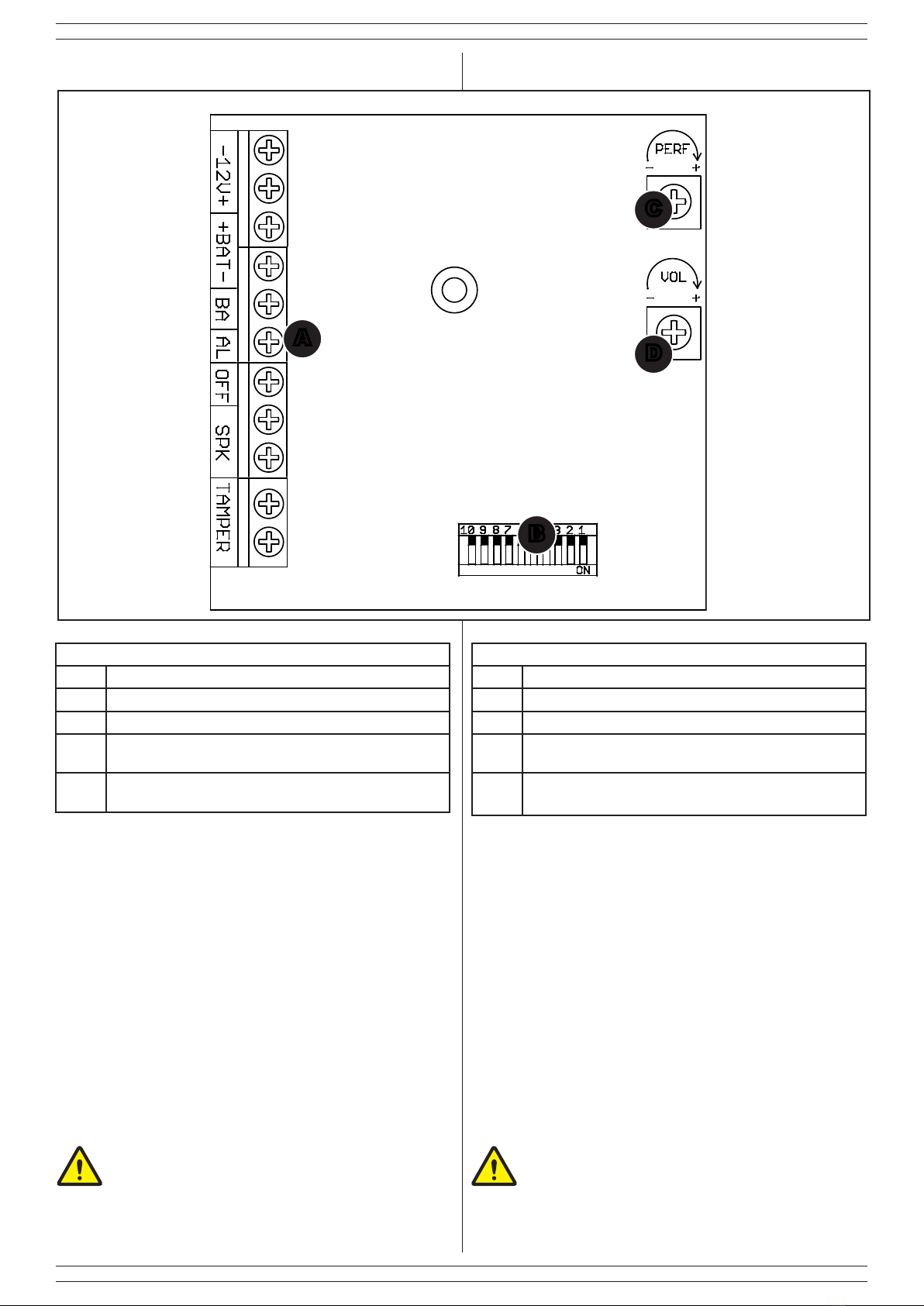
Al terminine dell'ìnstallazione è possibile regolare il volume
dell'altroparlante agendo sul trimmer Dg.3
2.7 SIREN INITIALIZATION
Powering the siren by battery or control panel, the ashlight
moduleisactivatedemittingaashevery4seconds(slow)for.
After the last operation, i.e. closure of the microswitch AS, if
everythingisOK, ashing becomesfaster, one ashevery1.5
seconds.
Afteroneminutetheashgoesoffandthesirenisreadytowork.
If there is a problem (e.g. no control panel power supply, tamper
contact open, battery failure or not connected, broken speaker)
whenclosingthecovertheashlightmodulewillcontinuetobe
slow, indicating afault;the ashing becomesfaster only when
everything is working.
Only for 8159-ISS024 and 8160-ISS025 the anti-approach
function performs a self-test lasting 3 minutes during which the
AS output does not switch
To complete the installation is not necessary to connect the
terminals BA and AS to the control panel. In case of reverse
polarity of the battery, the installation won' t be successfully
completed, while if it occurs after installation, the LED will
indicate both battery or power failure.
At the end of the installation it is possible to adjust the volume of
the loudspeaker by acting on the trimmer Dpict. 3
NOTE:
• collegare il morsetto AL della sirena al morsetto NC della
centrale e fare un ponticello sempre in centrale tra il morsetto
C e un positivo.
• Per lo stato impianto utilizzare un'uscita della centrale che
presenti un positivo a impianto disinserito.
• in caso di mancanza di collegamenti disponibili dalla
centrale, il morsetto AL può essere ponticellato o verso 12
V o verso GND (in base alla programmazione del DIP1) e
collegato in centrale sul morsetto del comando dedicato alla
sirena esterna o a uno scambio libero relè. Questo tipo di
collegamento potrebbe, però, compromettere la durata della
batteria nel tempo.
3. LOGICA DI FUNZIONAMENTO DEI
LED
3.1 LED DI ALLARME
NOTA:
il LED di allarme segnala anche la presenza contemporanea
di più anomalie. In caso siano presenti più anomalie, il LED
effettuerà una pausa di 2 secondi tra una sequenza e l'altra.
3. LED SIGNALLING MEANING
3.1 ALARM LED
NOTE:
The alarm LED could indicate the simultaneous presence of
multiple anomalies. in case of more issues, the LED will stop
for 2 seconds between each sequence.
Tabella 6
Lampeggi Signicato
1esistenza in vita ogni 60 secondi
3batteria scarica (<12V) o assente o guasta
6alimentazione < 11V;
9speaker o driver guasti solo se l’alimentazione supera
gli 11V
12 barriera IR antischiuma ostruita
Table 6
Flashes Meaning
1life-supervision each minute
3low (<12V), absent or faulty battery
6operating voltage < 11V
9speaker or driver failure only if operating voltage over
than 11V
12 anti-foam IR beam obstructed
2.8 FUNZIONE DI TEST (SOLO 8160-ISS025)
Se è disponibile una centrale di grado IV, collegare il morsetto
"T" al corrispondente morsetto sulla centrale per eseguire i test
richiesti dalla norma EN50131-4.
2.8 TEST FUNCTION (8160-ISS025 ONLY)
If a grade IV control panel is available, connect terminal "T" to the
corresponding terminal on the control panel to carry out the tests
required by the EN50131-4 standard.
NOTE:
• connect AL terminal of the siren to NC terminal of the control
panel and connect terminal C to a positive signal;
• For the system stauts use a control panel output that gives a
positive signal when the system is disarmed.
• in case of absence of available links from the control panel,
the AL terminal block can be linked to 12 Vdc or to GND
(according to the DIP1 programming) and connected inside
the control panel to the terminal block reserved for the siren
or to a relay. This type of connection, however, could affect
the durability of the battery.

9
ITALIANA SENSORI
5. ESEMPIO DI COLLEGAMENTO
-
12V+ + BAT - BA AL OFF SPK TAMPER
AUX
↓
OFF +N BA
AS AS
∗
∗
Fig. 5
5. EXAMPLE OF CONNECTION
SIRENA
SIREN
CENTRALE
CONTROL PANEL
Tabella 6
MORSETTO IDENTIFICAZIONE
AUX Alimentazione 12 Vdc
↓Massa comune
BA Ingresso di controllo della batteria
+N Positivo presente a riposo
OFF positivo presente a centrale disinserita
AS - AS
Linea di sabotaggio, collegarla per avere in centra-
le gli allrmi di apertura, strappo dal muro e funzioni
avanzate (se presenti)
Table 6
TERMINAL BLOCK DESCRIPTION
AUX Power supply 12 Vdc
↓Common ground
BA Battery control input
+N Positive present in stand-by
OFF positive present with control panel disarmed
AS - AS
H24 line, connect it to get informations about
alarms, tearing from the wall and advanced fun-
ctions (if present)
3.2 LED DI STATO
Il LED di stato permette di visualizzare lo stato dell’impianto
(secondo la programmazione del relativo dip).
Al raggiungimento di 5 allarmi consecutivi all’interno di una
stessa attivazione, il LED comincia a lampeggiare.
Per ripristinare la normale visualizzazione è necessario effettuare
un inserimento o un disinserimento.
3.2 STATUS LED
The status LED can display the system status (according to the
concerned dip).
Once reached 5 consecutive alarms within the same activation,
the LED begins to blink.
To restore the normal display you need to arm or disarm the
system.
(∗) Nello schema riportato, i morsetti segnati con l'asterisco sono
già cablati in fabbrica.
Nella tabella viene riportato il dettaglio dei morsetti di una
generica centrale a cui viene collegata la sirena.
(∗) In the diagram shown, the terminals marked with an asterisk
are already factory wired.
The table shows the detail of the terminals of a generic control
panel to which the siren is connected.

10
ITALIANA SENSORI
6. MANUTENZIONE E VERIFICHE PE-
RIODICHE
Alnedigarantireilcorrettofunzionamentodellasirena,ène-
cessario sostituire la batteria tampone ogni 2 anni.
ATTENZIONE! Per rimuovere sporcizie particolar-
mente evidenti NON utilizzare prodotti a base di clo-
ro,prodottiabrasivioppurealcool.
1. Pulire il coperchio con un panno inumidito con acqua.
2. Ripassare con un panno asciutto.
7. SMALTIMENTO E ROTTAMAZIONE
1. Svitarelevitichetengonossoilcoperchiofrontaleerimuo-
verlo.
2. Scollegare la scheda: sulla morsettiera scollegare tutti i mor-
setti (v. Fig. 3).
3. Dividere le parti in base alla loro tipologia e smaltirle in accor-
do con le leggi vigenti.
ATTENZIONE!
Non disperdere nell’ambiente i componenti ed ogni
altro materiale del prodotto.
Rivolgersi a consorzi abilitati allo smaltimento ed al riciclag-
gio dei materiali.
6. MAINTENANCE AND PERIODIC
CHECKS
In order to grant siren operating correctly, it is recommended to
replace the battery every 2 years.
IMPORTANT!
Do NOT use chlorine-based or abrasive products or
alcohol to remove particularly noticeable dirt.
1. Clean the cover with a cloth dampened with water.
2. Wipe with a dry cloth.
7. DISPOSAL AND SCRAPPING
1. Unscrew the screws that fasten the front cover and remove
it.
2. Disconnect the board: disconnect all the terminals on the ter-
minal block (see pict. 3).
3. Divide the parts by type and dispose of them in accordance to
applicable laws.
IMPORTANT!
Do not dispose of the components or any other pro-
duct material in the environment.
Seek the assistance of companies authorised to dispose of
and recycle waste materials.

11
NOTE
ITALIANA SENSORI

001530/00984SA Rev1
ITALIANA SENSORI
Marchio di LINCE ITALIA S.p.A.
Via Variante di Cancelliera snc
00072 Ariccia (RM) Italy
Tel. 06 92928252
Fax0692942586
www.italianasensori.it
This manual suits for next models
2
Table of contents
Other ITALIANA SENSORI Security System manuals