ELC LED2472 User manual

1. RENSEIGNEMENTS PRELIMINAIRES
Constructeur : elc 59, avenue des Romains 74000 ANNECY FRANCE
Téléphone : +33 (0)4 50 57 30 46 - Télécopie : +33 (0)4 50 57 45 19
Instrument : INDICATEUR NUMERIQUE
Marque : elc
Type : LED2472 V/A/T
Voltmètre ou Ampèremètre
2. DESCRIPTION
2.1 VUE D’ENSEMBLE
2-2 PRESENTATION
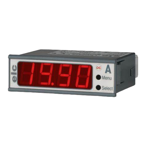
Vous venez d’acquérir un indicateur numérique 3 ½ digits elc type LED2472, nous vous remercions et
vous félicitons de votre choix. Cet appareil de tableau est destiné à des applications nécessitant une
mesure précise avec une bonne lisibilité dans un encombrement réduit.
Le LED2472 V/A (Voltmètre ou Ampèremètre) est un appareil multicalibre (configurable) capable
d’adapter sa mesure en fonction du signal d’entrée de manière automatique (Mode continu / alternatif).
Le mode alternatif consiste en une mesure TRMS fonctionnant sur 90% des signaux (sont à exclure les
signaux à front montant ou descendant rapide). L’affichage maximum en alternatif est de 1400pts. (la
tension ou le courant crête ne doit pas excéder 2000 pts). Le calibre est étalonné en usine.
Les LED2472 T (Ampèremètre pour transformateur d'intensité avec secondaire 5 Ampères) sont des
appareils multicalibres (8 calibres configurables) en alternatif. Deux modèles sont disponible :
TI400 : calibre 400/300/200/100/40/30/20/10 A ; TI800 : calibre 800/600/400/200/80/60/40/20 A.
2-3 CARACTERISTIQUES TECHNIQUES
Lecture : 4 afficheurs LED rouge de 14 mm.
Dérive thermique : 0,011% / °C (sauf calibre 200mA : 0.04%/°C ; 20mA : 0.022%/°C).
Précision : ± 0,1%, ±1 digit en continu et ± 0,25%, ±1 digit en alternatif sur le calibre
spécifié uniquement, les autres ±1% max.
Conversion : TRMS (Signalée par le battement des 2 segments de gauche sur l’afficheur).
Fréquence : 40 - 750 Hz.
Cadence d’affichage : de 1 à 3 mesure/seconde en DC et de 0,5 à 1.5 mesure/seconde en AC.
Virgule : quatre positions sélectionnables par bouton en face avant.
Dépassement : Affichage du mot «Err».
CONFIGURATION
(V/A) : sélection du mode : Auto, Continu ou Alternatif par bouton en face avant,
livré en Auto.
-EN CONTINU : Lecture 1999 points, positive et négative avec affichage du signe en négatif.
-EN ALTERNATIF : Lecture 1400 points.
CONFIGURATION
(T) : livré en Alternatif, lecture maxi 1400 points.
VOLTMETRE
Calibres disponibles : 2 V 20 V 200 V 500 V
Résolution : 1 mV 10 mV 100 mV 1 V
Lecture maxi. en DC. : 1.999 V 19.99 V 199.9 V 500 V
Lecture maxi. en AC. : 1.400 V 14.00 V 140.0 V 500 V
Tension maxi. : 180 V 500 V 500 V 600 V
Impédance d’entrée : 4 MΩsur tous les calibres.
AMPEREMETRE
Calibres disponibles : 100mV 2 mA 20 mA 200 mA 2 A
Résolution : 50 μV1μA 10 μA 100 μA1mA
Lecture maxi. en DC. : 19.99 1.999 mA 19.99 mA 199.9 mA 1.999 A
Lecture maxi. en AC. : 1400 1.400 mA 14.00 mA 140.0 mA 1.400 A
Tens / Courant maxi. : 9V 50 mA 160 mA 500 mA 2,5 A
Chute de tension max. : (4MΩ) 100 mV sur tous les calibres.
L'entrée 100mV permet de brancher un shunt 10A/50mV, 20A/100mV...
Pour ne pas avoir de problème de référence, il est conseillé d’alimenter les LED2472 par une alimentation
optionnelle (AL1040 ou AL48250) qui isole la mesure de l'alimentation.
Ces deux alimentations isolées galvaniquement ont été étudiées pour répondre aux demandes des utilisateurs.
Elles sont livrées avec une rallonge de boîtier et viennent s’emboîter à l’arrière du LED2472.
¾AL1040 : entrée de 9 à 40 VDC ou de 9 à 28 VAC (alimentation directe sur batterie ou transfo 12V, 24V).
¾AL48250 : entrée de 40 à 254 VAC ou de 40 à 350 VDC (alimentation 48V ou secteur direct)
5. ETALONNAGE - CALIBRATION
Les LED2472 sont ajustés en usine sur le calibre demandé. Après avoir changé de calibre et afin d'améliorer
sa précision, voici les réglages pour une calibration :
Nota : le recalibrage doit être fait par du personnel compétent avec des appareils reliés
aux étalons nationaux.
Calibrage Voltmètre / Ampèremètre : (Fig. 8)
¾AJ2 : Réglage du 0
¾AJ1 : Réglage du gain du calibre (pleine échelle)
6. MAINTENANCE
Aucun entretien n’est à envisager pour cet appareil. Eviter la poussière, l’humidité et les chocs.
7. SERVICE APRES VENTE
Cet appareil est garanti DEUX ANS pièces et main-d’oeuvre contre tous vices de fabrication, les frais de retour
sont à la charge du client. Seuls les appareils retournés avec une facture d’achat datée, pourront être couverts
par la garantie. Toute intervention sur l’appareil par des personnes ou organismes non agréés, fait perdre le
bénéfice de la garantie.
ANNEXE 1 : PRINCIPAUX SCHEMAS DE RACCORDEMENT
ATTENTION : La masse d’alimentation et l’entrée - de mesure sont reliées en interne.
Si l’on veut mesurer deux tensions n’ayant pas la même référence, sur deux indicateurs numériques,
l’alimentation pour le fonctionnement de ceux-ci ne pourra être unique. Il faut les alimenter séparément par
les options AL1040 ou AL48250 détaillées au § 4.
Dans le cas d’une lecture tension et courant, le montage d’un voltmètre et d’un ampèremètre avec
alimentation commune est possible uniquement si : Æl’ampèremètre est dans le circuit moins (-).
Æle voltmètre est branché en amont de l’ampèremètre.
Les entrées - et les masses sont communes. Raccorder en un seul point : l’entrée e- du LED2472 courant.
NOTICE D’UTILISATION DE L’INDICATEUR NUMERIQUE LED2472
Voltmètre / Ampèremètre / Ampèremètre TI xxx/5A
AJ1
AJ2
Fig. 8
4000 4 326 - 05/12
LED 2472
TENSION
V alim.
m
e+
e-
Utilisation =
ou
LED 2472
COURANT
V alim.
m
e+ e-
Utilisation =
ou
LED 2472
COURANT
e- e+
V alim.
m
Utilisation =
ou
LED 2472
TENSION LED 2472
COURANT
e- e+
m
e+
e-
m
V alim.
Utilisation =
ou
ATTENTION
V alim 1
séparée de
V alim 2
Utilisation =
ou
LED 2472
COURANT
V alim.
m
e+ e-
LED 2472
TENSION
e+
e-
m
V alim.
ATTENTION
V alim 1
séparée de
V alim 2
Utilisation =
ou
LED 2472
COURANT
V alim.
me+
e-
LED 2472
TENSION
e+
e-
m
V alim.
Utilisation =
ou
LED 2472
COURANT
me+
e-
LED 2472
TENSION
e+
e-
m
V alim.
AL1040
ou
AL48250
AL1040
ou
AL48250
LED 2472T
TI400
TI800
V alim.
Utilisation
m
e+A
e-
TI
5A
Utilisation
LED 2472
TENSION
e+
e-
m
V alim.
LED 2472T
TI400
TI800
e+A
e-
m
V alim.
5A LED 2472T
TI400/TI800
V alim.
m
e+A
e-
LED 2472T
TI400/TI800
m
e+A
e-
LED 2472T
TI400/TI800
m
e+A
e- L1
L2
L3
5A5A5A

LED2472T / TI400
Calibres disponibles : 400 A 300 A 200 A 100 A 40 A 30 A 20 A 10 A
Résolution : 1 A 1 A 1 A 1 A 0,1 A 0,1 A 0,1 A 0,1 A
Lecture maxi. : 400 A 300 A 200 A 100 A 40.0 A 30.0 A 20.0 A 10.0 A
LED2472T / TI800
Calibres disponibles : 800 A 600 A 400 A 200 A 80 A 60 A 40 A 20 A
Résolution : 1 A 1 A 1 A 1 A 0,1 A 0,1 A 0,1 A 0,1 A
Lecture maxi. : 800 A 600 A 400 A 200 A 80A 60.0 A 40.0 A 20.0 A
Courant maxi. adm. : 5,5 A quel que soit le calibre.
AUTRES CARACTERISTIQUES
Alimentation : +5 V, ± 5% régulée stabilisée, ou + 7,5 à 12 V redressée filtrée.
Consommation : 160 mA.
Option alimentation : deux alimentations isolées galvaniquement sont disponibles :
AL1040 : 9 - 28 VAC ou 8 - 40 VDC
AL48250 : 40 - 250 VAC ou 40 - 350 VDC
Raccordement : Borniers débrochables à vis pour fils de 2.5 mm².
Dimensions fenêtre : 24 x 72 mm.
Découpe à prévoir : 22,2 x 68 mm mini et 22,5 x 69 mm maxi. Epaisseur : 0,8 à 5mm
Indice de protection : IP 44 sur la face avant, après montage ; IP 31 à l'arrière du produit.
Conditions d'utilisation : +5°C à +50°C Conditions de stockage : -10°C à +60°C
Conditions d'humidité : voir figure ci-contre.
3. MISE EN SERVICE
3-1 DÉBALLAGE ET INSPECTION
Votre indicateur a été testé et calibré puis soigneusement emballé avant l’expédition. Déballez l’appareil et
vérifiez qu’il n’a subi aucun dommage. Toute anomalie doit être immédiatement signalée.
Pour prévenir tout risque d’incendie ou d’explosion et assurer un bon fonctionnement de l’appareil,
respecter les consignes de sécurité suivantes :
Contrôle visuel : si l’on constate que l’indicateur a été endommagé, ne pas tenter de le faire fonctionner.
Montage : Il est conçu pour être monté sur une platine métallique ou non. Vérifier les dimensions de
découpe de la platine et respecter les instructions de montage (voir § 3-4).
ATTENTION : La masse d’alimentation et l’entrée - de mesure sont reliées en interne, de ce fait, la tension
d’alimentation servant au fonctionnement du LED2472 doit être impérativement isolée du secteur.
Tous les raccordements ou modifications de connexions devront se faire hors tension.
Il ne possède pas d’interrupteur, il est prêt à fonctionner dès qu’il est alimenté.
Humidité : Pour prévenir tout risque de détérioration, ne pas l’exposer à l’humidité.
Vapeur et gaz : Ne pas l’utiliser en présence de gaz ou vapeurs inflammables, cet environnement est
particulièrement dangereux.
3-2 CONFIGURATION
Configuration du calibre avant la mise en service :
"Mode de mesure". Sélectionner le mode par appui sur le bouton du bas (Auto, DC, AC, AC avec barres
clignotantes). Pour valider les sélections et sortir des menus, appuyer sur le bouton du haut.
MODE DE MESURE
pour Voltmètre / Ampèremètre (livré en "Auto" et sur le calibre demandé)
¾Auto : L’appareil est capable de déterminer de manière autonome s'il s’agit d’un signal alternatif
ou continu. Lecture TRMS (AC+DC). (Les barres verticales du 1er digit clignotent en présence de
tension alternative).
¾AC : l’appareil reste en mode alternatif (AC+DC). Il permet l’analyse TRMS des signaux.
(2 configurations de l'affichage : avec ou sans les barres verticales clignotantes du 1er digit).
¾DC : l’appareil reste en mode continu (DC). Il permet une cadence d’affichage plus rapide et un gain
en précision (le témoin "DC" s’éclaire en face avant).
¾- .- - - : permet de déplacer la virgule en fonction du calibre ; Affichage : 1.999 ; 19.99 ; 199.9 ; 1999.
MODE DE MESURE
pour Ampèremètre TI400/800 (livré en "AC" avec barres clignotantes, sur le calibre supérieur)
3-3 MONTAGE
Découpe à prévoir : 22,2 x 68mm mini, 22,5 x 69 mm maxi.
Procédure de montage sur une platine (un joint de silicone vous permet de garantir l'étanchéité)
Déconnecter les deux borniers débrochables et les câbler (ATTENTION, se reporter au § 4).
Reconnecter les borniers et engager l’afficheur jusqu’aux clips.
Tout en exerçant une légère pression sur les clips, introduisez complètement votre appareil.
4. RACCORDEMENT
TENSION / COURANT TI400 / TI800
Retirer les borniers puis la
partie arrière de l’afficheur
(à l’aide d’un petit tournevis).
Fig. 1 Fig. 2
Platine
Fig. 3 Fig. 4
Fig. 5
Fig. 7
Multicalibre
A l'aide des borniers, tirer le
circuit imprimé vers l'arrière, déplacer le cavalier pour configurer le calibre.
Les borniers B1 et B2 peuvent recevoir des fils jusqu’à 2.5mm².
Connexions mesure sur bornier B1
Raccorder la tension ou le courant suivant votre configuration en respectant les figures 6 ou 7.
ATTENTION : sur l'ampèremètre 2 A, sur le TI400 et sur le TI800, l'entrée mesure se fait sur le plot central (e+A)
et celui de droite (e-), du bornier B1.
Connexions alimentation sur bornier B2
Raccorder l'alimentation en respectant les figures 6 ou 7 ; deux types d’alimentations possible :
- soit +5 volts ± 5% régulée (à connecter sur le plot au milieu de B2)
- soit +7.5 à 12 volts redressée filtrée ± 5% d’ondulation (à connecter sur le plot à droite de B2)
ATTENTION : Quelle que soit la configuration, toutes les connexions doivent se faire hors tension.
Sur l'afficheur, les entrées "e- mesure" et "masse alimentation" sont reliées en interne.
Fig. 6
Entrée e-
et masse -
alimentation +7,5V à 12V
+5V
B2
B1
Entrée
e+A
MESURE
ALIMENTATION
OU
B2
B1
MESURE
ALIMENTATION
Entrée e+
Tension ou
Courant
(sauf 2 A)
Entrée
e+A 2 A
Entrée e-
et masse -
alimentation +5V +7,5V à 12V
OU
V
2V 20V 200V 500V
A
2mA 20mA 200mA 2 A 100mV
TI400 100/10A 200/20A 300/30A 400/40A
TI800 200/20A 400/40A 600/60A 800/80A
Cavalier
1
2
3
44
3
2
1
Configuration du mode de mesure et de la virgule au démarrage :
Principe des menus : Le bouton sous le LED "DC" permet de naviguer dans les menus, le bouton du bas
permet de modifier les paramètres.
Un 1er appui sur le bouton du haut sélectionne le menu "Positionnement virgule" ; le déplacement se fait
avec le bouton du bas. Après l'avoir positionnée, un 2ème appui sur le bouton du haut passe au menu

1. PRELIMINARY INFORMATIONS
Manufacturer : elc 59, avenue des Romains 74000 Annecy FRANCE
Phone : +33 (0)4 50 57 30 46 - Fax : +33 (0)4 50 57 45 19
Instrument : DIGITAL METER
Brand : elc
Type : LED2472 V / A / T
(Voltmeter or Ammeter)
2. DESCRIPTION
2.1 OVERVIEW
2-2 PRESENTATION
You have just purchased the elc digital meter 3 ½ digits LED2472. We thank you and congratulate you for
your good choice. This instrument is intended for applications requiring a precise measurement with a
good reading and with small dimensions.
LED2472 V/A (Voltmeter or Ammeter) can take several ranges, it is a configurable device. It is able to
automatically adjust its measurement according to the input signal (DC / AC mode).
The AC mode is a TRMS measurement working on 90% of the signals (except the wavefront signals
increasing or decreasing really quick). The maximum display in AC is 1400 pts (the voltage or current peak
should not exceed 2000 pts). The range is calibrated in our factory.
LED2472 T (Ammeter for current transformer with 5A secondary) can take several ranges (8 configurable
devices) in AC mode. Both models are available : TI400 : 400/300/200/100/40/30/20/10 A ; TI800 : 800/600/
400/200/80/60/40/20 A.
2-3 TECHNICAL FEATURES
Display : 4 digits 14 mm red LED.
Temperature drift : 0,011% / °C (except for 200mA : 0.04%/°C ; 20mA : 0.022%/°C).
Accuracy : ± 0,1%, ±1 digit DC and ± 0,25%, ±1 digit AC only on specified range, for
others ±1% max.
Display rate : 1 to 3 measure/second in DC mode and 0.5 to 1.5 measure/second in AC.
Decimal Point : four positions selectable by button on the front panel.
Excess : Display of the term "Err".
CONFIGURATION
(V/A) : selection of mode : Auto, DC or AC by button on the front panel,
delivered in Auto.
-DC : 1999 points reading, positive and negative with negative sign display.
-AC : 1400 points reading.
Frequency : 40 - 750 Hz.
Conversion : TRMS (Indicated by the flashing of two left segments on display).
CONFIGURATION (T)
:delivered in AC mode, 1400 points reading.
VOLTMETER
Available ranges : 2 V 20 V 200 V 500 V
Resolution : 1 mV 10 mV 100 mV 1 V
Max. reading in DC. : 1.999 V 19.99 V 199.9 V 500 V
Max. reading in AC. : 1.400 V 14.00 V 140.0 V 500 V
Max. voltage : 180 V 500 V 500 V 600 V
Input impedance : 4 MΩon every ranges.
AMMETER
Available ranges : 100mV 2 mA 20 mA 200 mA 2 A
Resolution : 50 μV1μA 10 μA 100 μA1mA
Max. reading in DC. : 19.99 1.999 mA 19.99 mA 199.9 mA 1.999 A
Max. reading in AC. : 1400 1.400 mA 14.00 mA 140.0 mA 1.400 A
Max. voltage/current : 9V 50 mA 160 mA 500 mA 2,5 A
Max. voltage fall : (4MΩ) 100 mV on every ranges.
The 100mV input allows the plugging of a 10A/50mV, 20A/100mV shunt...
AJ1
AJ2
Pic. 8
4000 4 326 - 05/12
LED2472 DIGITAL METER INSTRUCTIONS MANUAL
Voltmeter / Ammeter / Ammeter TI xxx/5A
LED 2472
VOLTAGE
V supply
m
e+
e-
Use DC
or AC
LED 2472
CURRENT
V supply
m
e+ e-
Use DC
LED 2472
CURRENT
e- e+
V supply
m
Use DC
or AC
LED 2472
VOLTAGE LED 2472
CURRENT
e- e+
m
e+
e-
m
V supply
Use DC
or AC
LED 2472
CURRENT
V supply
m
e+ e-
LED 2472
VOLTAGE
e+
e-
m
V supply
Use DC
or AC
CAUTION
V supply 1
separated
from
V supply 2
CAUTION
V supply 1
separated
from
V supply 2
LED 2472
CURRENT
V supply
m
e+
e-
LED 2472
VOLTAGE
e+
e-m
V supply
Use DC
or AC
m
e+
e-
e+
e-
m
AL1040
or
AL48250
AL1040
or
AL48250
LED 2472
CURRENT
V supply
LED 2472
VOLTAGE
Use DC
or AC
LED 2472T
TI400
TI800
m
e+A
e-
TI
5A
V supply
Use AC
LED 2472
VOLTAGE
e+
e-
m
LED 2472T
TI400
TI800
e+A
e-
m
V supply
Use AC
LED 2472T
TI400/TI800
m
e+A
e-
LED 2472T
TI400/TI800
m
e+A
e-
LED 2472T
TI400/TI800
m
e+A
e- L1
L2
L3
V supply
Use AC
5A5A5A
5A
In order to avoid reference problems, we advise you to supply the LED2472 by an optional power supply
(AL1040 or AL48250) that insulate the power supply measurement. Indeed, on the initial version, the input
"measurement" and "power supply" are internally linked.
These 2 galvanic insulated power supplies have been studied to meet user's needs :
They are delivered with an extension box that is clipsable to the back of LED2472.
¾AL1040 : input from 9 to 40 VDC or from 9 to 28 VAC (direct power supply on the battery or transformator
12 V, 24 V)
¾AL48250 : input from 40 to 254 VAC or from 40 to 350 VDC (48 V power supply or direct main).
5. CALIBRATION - CONFIGURATION
LED2472 are adjusted in our factory to the required range.
However, below are the adjustments if you want to change its calibration :
Nota : the recalibration or checking must be done by qualified technicians with
instruments linked to national standards of measure.
Calibration : (Pic. 8)
ÎAJ2 : Adjustment of 0
ÎAJ1 : Adjustment of range gain (full scale)
6. MAINTENANCE
No particular maintenance is required for this instrument. Avoid dust, moisture and shocks.
7. AFTER SALES SERVICE
During TWO YEARS, spare parts and workmanship are guaranteed. This guarantee does not apply to
instrument presenting defects or failures caused by an improper use. Return expenses are borne by the client.
Only devices returned with a dated purchasing invoice can be recovered by the guarantee. Any intervention
carried out by unauthorized persons or organizations, shall void the guarantee.
APPENDIX 1 : MAIN CONNECTION DIAGRAM
CAUTION: Power supply chassis and "-" measurement input are internally linked.
If you want to measure on 2 digital meters, 2 voltages which have not the same reference, the power
supply to make them work can not be the same. They have to be supplied separately with the optional
supplies AL1040 ou AL48250 detailed at § 4.
In the case of a voltage or current reading, the mounting of a voltmeter and an ammeter with common
power supplies is only possible if : Æthe ammeter is in the negative circuit (-).
Æthe voltmeter is plugged upstream of the ammeter.
The "-" inputs and chassis are common. Connect into only one point : the e- input of the LED2472 current.

LED2472T / TI400
Cabled ranges : 400 A 300 A 200 A 100 A 40 A 30 A 20 A 10 A
Résolution : 1 A 1 A 1 A 1 A 0,1 A 0,1 A 0,1 A 0,1 A
Reading : 400 A 300 A 200 A 100 A 40.0 A 30.0 A 20.0 A 10.0 A
LED2472T / TI800
Cabled ranges : 800 A 600 A 400 A 200 A 80 A 60 A 40 A 20 A
Résolution : 1 A 1 A 1 A 1 A 0,1 A 0,1 A 0,1 A 0,1 A
Reading : 800 A 600 A 400 A 200 A 80A 60.0 A 40.0 A 20.0 A
Max current : 5,5 A on all ranges.
OTHERS FEATURES
Input voltage : +5 V, ± 5% regulated, stabilized, or + 7,5 à 12 V filtered rectified.
Consumption : 160 mA.
Optional power supplies: 2 galvanic insulated power supplies are available :
AL1040 : 9 - 28 VAC or 8 - 40 VDC
AL48250 : 40 - 250 VAC or 40 - 350 VDC
Connection : Disconnect screw terminal blocks for max 2.5 mm² wires.
Windows dimensions : 24 x 72 mm.
Cut out dimensions : 22,2 x 68 mm mini and 22,5 x 69 mm max. Thickness : 0,8 to 5mm
Protection level : IP 44 on the front after mounting ; IP 31 on the back.
Conditions of use : +5°C to +50°C Conditions of storage : -10°C to +60°C
Conditions of moisture : see graph
3. INTRODUCTION
3-1 UNPACKING AND CHECKING
Your digital meter has been tested and calibrated and carefully packed before shipment. Unpack the
instrument and check if it did not suffer from any damage. Any anomaly must immediately be pointed out.
To prevent any fire or explosion risks and ensure a good operation of the instrument, respect the safety
instructions below :
Visual control : if the LED2472 has been damaged, do not try to make it work.
Mounting : it is made to be installed on plane surfaces. Check cut out dimensions and respect the
mounting instructions (see § 3-4).
CAUTION : The power supply and chassis input are internally linked. Therefore, the useful input voltage for
the operation of the LED2472 must imperatively be insulated from the main input voltage.
All connections or modifications of the connections must be done out of voltage.
There is no switch, it is ready to work as soon as it is plugged.
Moisture : To prevent all deterioration risks, do not expose to moisture.
Fumes and gas : Do not use in a gas or flammable fumes environment, this is especially dangerous.
3-2 CONFIGURATION
Configuration of range before starting :
menu "Measuring mode". Select mode by pressing the bottom button (Auto, DC, AC, AC with flashing
bars). To confirm the selections and exit the menus, press the top button.
CONFIGURATION
Voltmeter / Ammeter (delivered Auto and on the required range)
¾Auto : LED2472 is able to determine in an autonomous way if it deals with an AC or DC signal.
TRMS (AC+DC) reading (the vertical bars on 1st digit flashes in AC voltage).
¾AC : The device stays in AC mode (AC+DC). It enables TRMS signal analysis.
(2 possible configurations : with or without the vertical bars on 1st digit flashing in AC voltage)
¾DC : The device stays in DC mode (DC). It enables a faster display and an accuracy gain.
(DC indicator lights up on front panel)
¾- .- - - : enables to move the decimal point according to the range ; Display : 1.999 ; 19.99 ; 199.9 ; 1999.
CONFIGURATION
TI400 and TI800 (delivered in AC mode with bars flashing and on the highest range)
3-3 MOUNTING
Cut out to forecast : 22,2 x 68mm mini, 22,5 x 69 mm max.
Mounting procedure on a plane surface (a silicon joint enables its sealing)
Disconnect the 2 disconnect screw terminal blocks and cable them. (CAUTION, refer to § 4).
Reconnect these terminal blocks and insert the digital meter until the clips. While pressing lightly on the clips,
insert it completely.
4. CONNECTION
VOLTAGE / CURRENT TI400 / TI800
Terminals B1 and B2 can accept wires until 2,5 mm².
Measuring connection on terminal B1
Connect voltage or current following your configuration respecting Pic. 6 or 7.
CAUTION : on ammeter 2 A, TI400 and TI800, inputs are on (e+A) in the middle plate and (e-) on the right of
the B1 terminal block.
Power supply connection on terminal B2
Connect the power supply respecting Pic 6 or 7. Two types of power supplies are possible :
- either +5 volts ± 5% regulated (to be connected on the middle plate B2)
- or +7,5 to 12 volts filtered and rectified ± 5% ripple (to be connected on the block at the right B2).
CAUTION : Whatever the configuration, all connections must be done outvoltage.
On the display, input "e-measure" and "ground power supply" are connected internally.
Pic. 1
Plane
surface
Pic. 3 Pic. 4
Pic. 5
Pic. 6 Pic. 7
Take the connectors blocks
off, then the back part of the
indicator (thanks to a small
screwdriver).
8
0
5
0
3 1 4 0 ° C
%
m a x i m u m r e l a t i v e
m o i s t u r e
Thanks to the connectors
block, pull the PCB backwards and move the jumpers to configure.
Pic. 2 Multicalibre
Input e+
voltage
or current
(except 2A)
Input e-
GND Supply +7,5V to 12V
OR
+5V
B2
B1
MEASUREMENT
SUPPLY
Input
e+A 2A
+7,5V to 12V
OR
+5V
B2
B1
MEASUREMENT
SUPPLY
Input
e+A
Input e-
GND Supply
V
2V 20V 200V 500V
A
2mA 20mA 200mA 2 A 100mV
TI400 100/10A 200/20A 300/30A 400/40A
TI800 200/20A 400/40A 600/60A 800/80A
jumper
1
2
3
44
3
2
1
Setting the measurement mode and starting point :
Principle of menus: The button under the LED "DC" is used to navigate through menus, the bottom button
to change settings. A first pressing the top button selects the menu "Decimal point"; the displacement is
made with the bottom button. After having positioned, a second pressing on the top button goes to the
Table of contents
Languages:
Other ELC Measuring Instrument manuals
Popular Measuring Instrument manuals by other brands

FoamPRO
FoamPRO 3012 Installation and operation manual
Swann
Swann AMI Hydrogen QED Operator's manual
Major tech
Major tech MTD75T instruction manual
THE ELECTRON MACHINE CORPORATION
THE ELECTRON MACHINE CORPORATION DSA E-Scan Operating and service manual
ORBECO
ORBECO MC500 instruction manual

MATO
MATO DIGIMET E35 operating instructions
