APS LSC Instruction Manual

APS Annunciator System LSC
Installation & User Manual

2
LSC
Content
Safety and installation........................................................................................3
Installation:............................................................................................................................3
Fitting:...................................................................................................................................3
Supplementary power:..........................................................................................................3
Wiring:...................................................................................................................................3
Connection principle: ............................................................................................................4
System features.................................................................................................5
System components..........................................................................................5
System expansion capability..............................................................................5
Installation .........................................................................................................6
Setting the module ID-address: ............................................................................................6
Factory settings:....................................................................................................................7
CAN-Bus:..............................................................................................................................8
Installation check list..........................................................................................9
Basic Module BM.............................................................................................10
Application & Characteristics ..............................................................................................10
Function:.............................................................................................................................10
Technical data:....................................................................................................................10
Wiring diagram:...................................................................................................................11
Relay Module RM............................................................................................12
Application & Characteristics ..............................................................................................12
Function:.............................................................................................................................12
Technical data:....................................................................................................................12
Wiring diagram:...................................................................................................................13
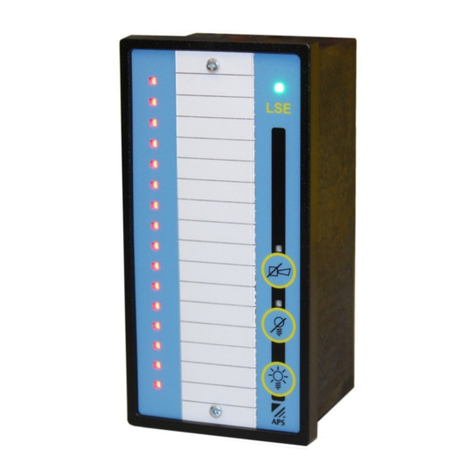
Panel Module PM............................................................................................14
Application & Characteristics ..............................................................................................14
Function..............................................................................................................................14
Technical data.....................................................................................................................14
Wiring diagram:...................................................................................................................15
Bus connector CIM..........................................................................................15
Application & Characteristics ..............................................................................................15
Additional information......................................................................................16
Programming......................................................................................................................16
Order overview................................................................................................16

3
LSC
Safety and installation
Before commissioning the LSC Annunciator System please read the following notes for your
safety and for the operating safety of the equipment.
Installation:
Installation work must be carried out by certified technical staff only. Follow the instructions in
this handbook, and heed the notes on dangers. Observe the locally applicable regulations for
the safe and riskless handling of electrical installations.
Fitting:
The BM Basic Module the RM Relay Module and the CIM Connector of the LSC System are
fitted on top-hat mounting rails (DIN rails). The PM Panel Module is fitted into a control panel.
On the rear side of the PM a hat rail is provided for the mounting of a Basic Module.
Supplementary power:
Power supplies for the signal voltage (inputs and outputs and for the voltage supply of the
LSC system must comply with the stipulations for safety extra-low voltage (SELV) given in
IEC 346-4-41. We recommend our power supplies of the EcoPower Series as they fulfil these
stipulations completely.
Wiring:
The wiring for the voltage supply and for the various inputs and outputs is connected to the
terminals of the module. The connection of the modules to each other is effected with factory-
made cables.
At its begin and end the BUS must be terminated with a resistor. This termination resistor is
on the Basic- and Relay Module and it is connecting to the BUS with switch 1 on the
modules.
The power circuit for the voltage supply (system supply) must be fused by an external excess
current fuse. For its calculation the current consumption of an LSC System is determined by
the total of the current consumption of the modules being used (see "Technical Data" page).
The LSC System does not have its own master switch for switching off the voltage supply,
therefore an external switch must be provided for this purpose.
This must be located in the vicinity of the LSC System. The switch must be easily accessible
to the operator and must be marked as a cut-off device for the LSC System.
The power circuit for the inputs and outputs must be protected by external excess current
protection devices (for current consumption of the inputs and the current carrying capacity of
the outputs see "Technical Data").
The minimum diameter of cables used for the CAN-Bus must be 0.5mm
2
.

4
LSC
Connection principle:

5
LSC
System features
Modular system: For the processing of new value/first-up value alarms
in accordance with DIN 19235:
oBuilding services and building automation
oControl systems
oProcess automation
oPower transmission, power distribution
oTransport
oCommunication
On-Delay: Individually On-delay setting for all in- and outputs up
to 47 minutes
Serial interface: For networking (BUS coupling)
RS232 interface: For configuration via PC and expansion functions
System components
BM Basic Module: Basic module with 8 signal inputs with RS232 interface
(Housing for DIN-rail mounting)
RM Relay Module: Expansion device with 8 relay outputs only RS232 interface
(Housing for DIN-rail mounting)
PM Panel Module: Optional module for external indication (Front mounted)
CIM-Connector: Interface between system-bus and building cabling
System expansion capability
BM Basic Module: Maximum 8 modules (64 alarm inputs)
RM Relay Module: Maximum 8 modules (64 relay outputs)
PM Panel Module: Maximum 8 external units
CIM-Connector: Maximum bus distance 1000m

6
LSC
Installation
Before commissioning the unit you are recommended to check the installation with the aid of
the check list for installation/fault finding.
Before switching on the voltage supply and the supply for the inputs and outputs you must
ensure that the voltage values are within the permissible limits (see Technical Data). Voltage
which is too high or false polarity of the voltage can lead to damage of the LSC System.
After switching on the voltage supply of the LSC System (system voltage) the green LED
"POWER ON" on the Basic Module must light up. If this is not the case, then the system
voltage is outside the permissible range. If you use more than one device (e.g. two BM and
one RM) you need to set the module addresses as explained below.
Then every individual function of the LSC System must be checked. In doing so, not only
must the configuration of the system be verified but also the external wiring and the
interaction with connected equipment. Before testing take precautions that a (possibly
inadvertent) activation of the outputs in association with equipment connected to them cannot
lead to dangerous operating states. When testing, all inputs must be systematically activated
in turn and the reaction of the system checked for its correctness.
Setting the module ID-address:
Please refer to the following points to set the module ID-addresses:
oTurn off the supply voltage of the module.
oPress and hold the lamp-test button, meanwhile turn on the supply voltage.
oThe actual module address is now showed as follows:
-All LED are activated for stand alone (factory setting)
-One of the LED 1 to 8 blinks (ID already set).
oRelease the lamp test button and press it again to set the ID address. With every
pressing the address counts one up, shown by the appropriate blinking LED.
oPress and hold the lamp test button for 3 seconds to save your settings. After
successfully saving your changes, the module acknowledges with a beep tone and
switches back to operation mode.
Lamp test button

7
* factory setting
LSC
Warning:
If you are using a single Basic Module BM the address has to be set to the stand alone mode
(all LED are blinking) which is factory setting. Otherwise, a bus error will occur.
Important:
If you are in the module ID address setting process and do not press any button for six
seconds, the module will switch back to operation mode without saving your changes. Please
note that changing the module ID address may cause a bus error on an other module.
LED
blinking ID-address LED
blinking ID-address
1 0 6 5
2 1 7 6
3 2 8 7
4 3 1 – 8* 8*
5 4
Factory settings:
Please refer to the following points to set a Basic Module BM back to factory settings:
oTurn of the supply voltage.
oPress and hold the two buttons lamp test and horn acknowledgement, then turn on the
supply voltage.
oThe module acknowledges the restoration of the factory settings by beeping three
times.
Button horn acknowledgement
Button lamp test
Important:
The procedure has to be repeated for every module you wish to set back. The restroing of
the factory settings will also change the module address to stand alone, this may cause a bus
error.

8
LSC
Please refer to the following points to set a Relay Module RM back to factory settings:
oTurn of the supply voltage.
oPress and hold the lamp test button, then turn on the supply voltage
oLet go the lamp test button and press it again for three seconds to acknowledge.
Button lamp test
CAN-Bus:
In case of a bus error, the two LED „Bus“ and „Horn“ are showing which type of error it is:
LED
Bus LED
Horn Type of the error
Bus OFF: The module has switched off the bus. Possible reasons are a
short circuit or a module operating with the same module ID-address.
Connection error: The module has no connection to the bus.
Bus conflict: Several modules are using the same module ID-address.
Failure neighbour module: The next module has lost it’s connection or
does not work properly .
Steady light
flashing
Important:
After having successfully resolved a CAN-bus error, it is recommended to completely restart
the LSC system by turning off an on again the supply voltage.

9
LSC
Installation check list
Checkpoint Module Connectors Installation Check
Supply voltage Power supply
Alarm voltage Power supply
BM 1/2
Supply voltage (connection) RM 1/2
First Switch ON 1
Termination resistor Last Switch ON 1
Alarm inputs + BM 8-15
Alarm inputs - BM 7
Horn acknowledgement + BM 4
Horn acknowledgement - BM 3
Lamp acknowledgement + BM 5
Lamp acknowledgement - BM 3
Lamp test + BM 6
Lamp test - BM 3
Relay output horn BM 20/21
Group alarm BM 18/19
Relay common alarm BM 16/17
Potential-free contacts RM 8/9 – 22/23
Connections All Bus
Module address BM/RM
Configuration

10
LSC
Basic Module BM
Application & Characteristics
The BM Basic Module is the foundation stone of the modularly expandable LSC product
family. The BM Basic Module is supplied in the installation housing for top-hat rail mounting.
o8 operation indicator
oIntegrated buzzer
o8 alarm inputs NO/NC with individual time delay
o3 system inputs and outputs
oCAN Bus interface for networking (BUS coupling) and RS 232 interface
oIntegrated buttons: Lamp test, Horn acknowledgement and Lamp acknowledgement
oTwo LED showing the status of the supply voltage and the bus function
oThree LED showing the status of the horn-, group- and common relay
Function:
Each alarm occurring is acoustically and visually indicated on the unit. When an alarm is
signalled the horn annunciator relay is activated and the LED for this relay is illuminated.
After expiry of the set delay time the relays for collective alarm and group alarm are triggered
and signalled with a LED in accordance with the operating mode set. After the expiry of the
preset delay time the fault is indicated at the alarm input by the blinking of the related LED.
Horn acknowledgement The integrated buzzer and the relay contact for the
horn are switched off
Lamp acknowledgement LED goes out or changes to continuous light if the
input is still activated.
Lamp test All LED are activated for five seconds.
Technical data:
Housing 87x90x58mm
Mounting position Any
Connections Cage Clamp 2,5mm2
Permissible ambient temperature 0°C bis + 55°C
Protection degree IP20
Supply voltage 24VDC +/- 20%
Signal voltage 24VDC (15-30 VDC)
Flashing frequency 1Hz
Switching capacity of relay contacts Max. 3A/250VDC
Max. power consumption 3.5W
Response delay Appr. 10mS
Weight 200g

11
LSC
Wiring diagram:

12
LSC
Relay Module RM
Application & Characteristics
The Relay Module RM provides 8 potential free contacts which could be used to build an
external signalising or switch other devices. The BM Basic Module is supplied in the
installation housing for top-hat rail mounting.
o8-channel relay module
oContact load carrying up to 250 VAC / 3 A per relay output
oNormally open or normally closed current principles
oExpandable up to 64 relay outputs (NO/NC)
oLED indicator per relay
oFunction of relay outputs conforming to DIN 19235
oCAN Bus interface for networking (BUS coupling)
oIntegrated lamp test button
oBuilt in LED showing the status of the supply voltage and the bus function
Function:
The control of the Relay Module RM is effected via the internal BUS. Optionally, the alarm
inputs can be linked with the individual outputs of the Relay Module (OR–linking of the alarm
inputs).
Button lamp test All LED are activated for appr. five seconds.
Outputs in “BLINK” mode are activated too
Technical data:
Housing 87x90x58mm
Mounting positon Any
Connections Cage Clamp 2,5mm2
Permissible ambient temperature 0°C bis + 55°C
Protection degree IP20
Supply voltage 24VDC +/- 20%
Signal voltage 24VDC (15-30 VDC)
Flashing frequency 1Hz
Max. load of the relay contacts Max. 3A/250VDC
Mechanical relay life span 10
7
switching cycles
Max. power consumption 4W
Weight 220g

13
LSC
Wiring diagram:

14
LSC
Panel Module PM
Application & Characteristics
The Panel Module PM acts as an external display in cabinet fronts. It is driven by the BM to
which it is connected. The maximum distance between PM and BM is 3 meters.
o8 operation indicator
oIntegrated buzzer
oRS 232 interface
oIntegrated buttons: Lamp test, Horn acknowledgement and Lamp acknowledgement
oLED showing the status of the supply voltage
oThree LED showing the status of the horn-, group- and common relay
Function
The PM has a red LED for each signal input of the BM. Furthermore, it has green LED for the
system outputs. The LED are illuminated when a signal input or a system output is active.
Horn acknowledgement The integrated buzzer and the relay contact for the
horn are switched off
Lamp acknowledgement LED goes out or changes to continuous light if the
input is still activated.
Lamp test All LED are activated for five seconds.
Technical data
Housing 96x96x51mm
Mounting position Any
Front panel cut-out 91x91mm
Ambien temperaure 0°C bis + 55°C
Protection degree IP40
Supply voltage Supplied through BM
Flashing frequency 1Hz
Weight 170g

15
LSC
Wiring diagram:
Bus connector CIM
Application & Characteristics
When you are using modules at different venues, the CIM bus connector is the interface
between the cabling. The CIM provides a plug for the standard BCC cable on one side and
cage clamp connectors on the other side. The CIM can be clamped on a DIN-rail.

16
APS systems AG Tel. +41 (0)62 389 88 88
Neumatt 4 Fax. +41 (0)62 389 88 80
LSC
Additional information
Programming
First of all, the module ID adresses have to be set on every module, see page 6. When the
bus works properly, start the further programming with the free software. Please download
the latest version on our homepage:
www.aps-systems.ch
Do not forget to make a safety copy after finishing your work.
Order overview
832.600.012 BM Basic Module
832.600.022 RM Relay Module
832.600.000 PM Panel Module
832.600.031 BCCS4 Bus cable 0.2m, 4-poles
832.600.030 BCCS6 Bus cable 0.1m, 6-poles
832.600.033 BCCL6 Bus cable 3.0m, 6-poles
832.600.032 CIM Bus Connector DIN rail-mounted
832.600.095 LSC configuration cable
832.600.903 Replacement insertion tags for the PM (3 pcs.)
832.600.904 Replacement insertion tags for the BM/RM (3 pcs.)
862.332.420 Power supply EcoPower PSS242 24VDC/2A
862.332.430 Power supply EcoPower PSS243 24VDC/3A
Doc-0001-E 02.10
Table of contents
Other APS Measuring Instrument manuals