ELC focus BRAIN XL User manual

focus BRAIN XL
512 channel intelligent wireless DMX riggers remote
Users Manual
Software version: 3.0
Version: 0404
2
focus BRAIN XL
System description
focus BRAIN is the enhanced version of the success full focus
HAND. Where the focus hand was mainly meant as a third
hand for focusing lighting fixtures, replacing the person behind
the lighting desk and the intercom. The focus BRAIN has more
possibility’s.
•Intelligent wireless remote control for DMX-512
•512 Channels selectable from ranges 1-512 or 513-1024
•Connected between console and dimmers
•Merging remote- and console DMX in HTP
•51 memory’s
•50 groups
•X-Fade possibility, x-fadetime can be programmed to each
memory
•Focus and Scene mode
•Direct memory mode, including Go button
•2 Contact closure inputs, as Go or emergency scene
•2 Contact closure outputs, to be controlled by the remote
•Remote (de-)activation
•Hardware bypass via a relay in case of power failure
The focus BRAIN can store and recall up to 51 memories.
These memories can be created on the remote unit’s and / or
capture of the DMX input from the lighting desk. Memories can
be called up directly or with a x-fade time up to 10 sec. The x-
fadetime can be programmed for each memory individually. A
default memory can be created to be automatically recalled at
power on.
The DMX input from the lighting desk can be merged with the
DMX created inside, so that 1 person can focus the fixtures
while the other is programming the lighting desk.
This means focus BRAIN is a versatile controller for the lighting
This product may only be used for controlling dimmers and
moving lights. Using the product out of these specifications will
remove all responsibility from the supplier

3
Getting Started
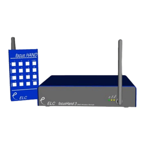
The focus BRAIN XL system consists of 3 parts, the remote,
antenna and 19”-unit.
The remote unit
The remote has 16 keys and 1 slide switch. The slide switch is
for power on. However the power consumption is minimal, so
battery life is not really shortened, because depressing a key
activates the unit. The switch is mainly used as a safety
against unwanted key presses when the unit is in the pocket.
Battery replacement
Because of the often rough circumstances in which the unit
can be used, the battery compartment is closed with normal
M3 screws instead of clips. To replace the battery, remove the
two screws at the bottom, replace it with a fresh one and close
the lid with the same (4mm) screws. Be sure not to throw the
old battery in the normal dustbin, but remove it adequately.
Using alkaline batteries is recommended.
Keypad layout
1
Up
4
Down
7
Next
0
Prev
2
5
8
Focus
+
Memory
3
6
9
Scene
-
Store
Func
@
Enter
4
Key illumination
The keys on the unit are illuminated. While a key is pressed
the unit is transmitting, indicated by bright illumination of the
keys. When releasing the key the illumination stays on for a
period of time. The time(out) can be programmed on the
remote unit following these steps:
1) switch off the remote unit (slide switch on top)
2) press and hold FUNC, @, or ENTER
3) switch on the remote unit (slide switch)
4) wait until keys are blinking (±5 sec)
5) release the key
The time is now programmed to:
Key Time
FUNC 5 seconds
@ 12 seconds
25 seconds
ENTER
never turn off
Active antenna
However the range indoors is specified up to 70m, steel tubing
(trusses/pipes) and building skeletons can influence this. To
overcome this problem the active antenna is separate from the
receiver unit. The connection in between is standard
microphone cable, up to 100m. The best position for the
antenna is in the middle above the front of the stage.

5
Main 19” unit
The receiver has 4 connections plus a mains input. The mains
input voltage can be selected 110V(115V) or 220V(230V) on
the back. Connections are the DMX input and DMX output on
5 pin XLR.
DMX connection
Pin Description
1 Ground/Screen
2 Data -
3 Data +
4 loop thru to other XLR5 pin 4
5 loop thru to other XLR5 pin 5
When the power is off or the unit is not activated the DMX
input is directly connected to the DMX output by a relay.
RS-232 connection (SUB D9 female) for software updates.
Pin Description
1 -
2 TX
3 RX
4 -
5 Ground
6 -
7 Reserved
8 Reserved
9 -
3 pin XLR connection is for the active antenna.
Pin Description
1 Ground/Screen
2 Signal
3 +8V supply
6
The LED’s on the front indicate power on, active, receive and
DMX input.
LED Meaning
On Power is on and internal processor is working
Active DMX control is taken over from the lighting desk
Receive Signal is received from the remote
DMX DMX input ok
On the back of the 19”-receiver unit there are 4 switches for
option selection.
Switch Off On
1 Default focus mode Default scene mode
2 DMX-A (channel 1-512) DMX-B (channel 513-1024)
3 Fast level selection Precise level selection
4 Normal operation Direct Memory
If all 4 dipswitches are down (On) the focus brain is in special
showstore mode. Look in the showtore manual for details.
Contact closure connection (SUB D9 female)
Pin Description
1 Shield
2 Output 1+
3 Output 2+
4 Input 1+
5 Input 2+
6 Output 1-
7 Output 2-
8 Input 1-
9 Input 2-

7
Operation
Activation / deactivation
The focus BRAIN must be activated in order to control the
dimmers. On activation the output DMX is sent from the FB
and can be the result of merging the DMX from the console
(DMX input) and the internally created DMX channels on a
HTP basis. On deactivation the DMX input is looped through
the FB.
To activate the unit, with merging enabled, press:
+ + Enter
To activate the unit, with merging disabled, press:
+ + 0 Enter
To switch on / off merging use + + Enter to enable merging,
+ + 0 Enter to disable merging.
To deactivate the unit press:
- - Enter
Dimmer selection
For dimmer selections there are 2 modes: Focus and Scene.
The Focus mode is intended for quickly selecting a single
dimmer or a group of dimmers and clearing the rest of the
stage. Each time a new set of dimmers is selected, all the
other channels are cleared. The Scene mode is intended for
easily creating a scene. When selecting a new set of dimmers
the other channels remain the same.
The default mode the FB comes up in is depended upon
dipswitch 1
Select a single dimmer at Full (100%)
1 Enter dimmer 1 at 100%
8
Selecting multiple dimmers at Full
2+5 Enter dimmers 2 and 5 at 100%
25 Enter dimmers 2 through 5 at 100%
25+9 Enter dimmers 2 through 5 and 9 at 100%
25–4 Enter dimmers 2,3 and 5 at 100%
Adding channels
To add channels in Scene Mode just use sequences
described above. In Focus Mode its necessary to “add”
channels by using + before your selection, other wise it will
clear all previously selected channels.
+5 Enter add channel 5 at 100%
Removing channels from the selection
To remove channels use –:
-6 Enter remove channel 6
-36 Enter remove channel 3 to 6
Remove all channels / Clear Stage
0 Enter clear all channels
Toggle / Undo
With Enter its possible to toggle between 2 settings. Each
change will make a new setting, so its possible to change to
the previous setting and back again.
1 Enter channel 1 at Full
3 Enter channel 3 at Full channel 1 clear (Focus)
Enter channel 1 at Full channel 3 clear
Enter channel 3 at Full channel 1 clear

9
Selecting the Channel level
The channel level can be set in two ways, quick and precise,
selectable by dipswitch 3. The quick mode uses only 2 key
presses. The precise uses 3 or 4 key presses.
Quick level Mode (dipswitch 3 is OFF)
To set a level in Quick level Mode press @ followed by 0 to 9
or Enter. 0 will clear the dimmer, 1 to 9 will give levels from
10% to 90% and Enter will give a level of 100%
… @ 0..9,Enter
1 @ 5 this will bring up dimmer 1 at 50%
34 @ 0 this will clear dimmer 34
Precise level Mode (dipswitch 3 is ON)
To set a level in Precise level mode press @ followed by 1 or
2 digits and Enter. When entering 1 digit, this will set the level
in 10%-steps. Using 2 digits it’s possible to set the level in 1%
steps. Pressing Enter directly after @, the level becomes
100%.
… @ [0..9] [0..9] Enter
1 @ 5 Enter dimmer 1 at 50%
1 @ 05 Enter dimmer 1 at 5%
3 @ 25 Enter dimmer 3 at 25%
Function Keys
With the Function key (Func) it is possible to call up the
secondary function of a key.
Adjusting level and stepping through channels
To step thru channels and adjust the level press Func, then
use Up, Down, Next and Prev. When finished press Enter. The
function of Up. Down, Next and Prev depends on the mode.
10
Focus Mode:
Up: Increase level of currently selected channels
Down: Decrease level of currently selected channels
Next: Shift up the selected channels
Prev: Shift down the selected channels
Scene Mode:
Up: Increase level of currently selected channels
Down: Decrease level of currently selected channels
Next: Shift up the selection of the channels
Prev: Shift down the selection of the channels
Selecting Focus or Scene Mode
With dipswitch 1 it’s possible to select the power up mode
focus/scene. This can be changed online by pressing:
Func Focus select focus mode
Func Scene select scene mode
Working with Groups
A group is a selection of 1 or more channels. The key is
used for groups. 50 groups (1 – 50) can be used.
To create a group, create a scene with all the channel you
want in the group at a level greater than 90%. This can also be
done by using the console connected on the DMX input.
To store the Group:
•Press Func
•Press (Thru)
•Type in the group number
•Press Enter
Using groups
Groups can be used during channel selection. The key is
used as GROUP.

11
Example
1 Enter
will set all the channels in group 1 to full
2 – 4 Enter
will set all the channels in group 2 except channel 4 to full
2 4 Enter
will set all the channels in group 2 and 4 to full
1 10 - 5 Enter
will set channels 1 thru 10 except the channels in group 5
to full
Memories
The Focus Brain can store up to 51 memories of all 512
channels. Recalling a memory will create a new setting. The
setting can be changed and saved as a different memory.
Storing a memory will store the full DMX output being a
merged combination of internal DMX and DMX input from the
console.
Memory Recall
To recall a memory press
Func Mem 1 Enter This will recall memory 1.
It is also possible to recall a memory with a fade time. The
fade time can be from 1 to 10 (digit 0 is 10) seconds. To select
recalling with fade time press @ [digit] instead of Enter after
the memory selection.
Func Mem 12 @ 5 This will recall memory 12 with a fade
time of 5 seconds
Memory Store
When storing a memory, the full DMX output including the
DMX input is stored if merging is enabled. To store a memory
press:
Func Store 1 Enter store memory 1
Func Store 23 Enter store memory 23
12
Storing a memory with a fade time is done by typing @ ..
instead of Enter:
Func Store 1 @ 1 store memory 1 with a fadetime of 1
second
Func Store 10 @ 0 store memory 10 with a fadetime of 10
secondes (digit 0 10)
Direct memory mode
In direct memory mode (dipswitch setting), the focus mode is
replaced by a memory selection mode. To recall a memory
type in the number and press enter.
10 Enter Recalls memory 10
10 @ 5 Recalls memory 10 in 5 sec fade
Pressing Enter will call up the next memory with it’s
programmed fade time, acting like a GO.
You can switch between memory selection and scene mode
by: Func Scene
Or back by: Func Focus
Memory 0: power on memory
If memory 0 is stored with at least 1 level higher then 0%, then
on power up the 19”-unit will be automatically activated and
memory 0 recalled with a fade time of 1 sec.
To store memory 0 press: Func Store 0 Enter
Contact Closure Inputs
The 2 contact closure inputs have the following functions,
when pulsed.
- Input1: recall memory 1, with it’s programmed fade time
- Input2: recall the next memory, with it’s fadetime
Contact Closure Outputs
The 2 contact closure outputs can be controlled by the remote
Func 2 + activate output 1
Func 2 - deactivate output 1
Func 3 + activate output 2
Func 3 - deactivate output 2
Press enter to go back to the main (selection) menu.

13
General Information
CE – Product
The Focus Brain System permits to the CE requirements set-
up by the European Community. This can be recognized by
this label on the outside of the product.
FCC NOTES (914,5MHz US version):
NOTE:
This equipment has been tested and found to comply with the
limits for a Class A digital device, pursuant to Part 15 of the
FCC rules. These limits are designed to provide reasonable
protection against harmful interference when the equipment is
operated in a commercial environment. This equipment
generates, uses and can radiate radio frequency energy and,
if not installed and used in accordance with the instruction
manual, may cause harmful interference to radio
communication. Operation of this equipment in a residential
area is likely to cause harmful interference in which case the
user will be required to correct the interference at his own
expense.
NOTE:
This device complies with part 15 of the FCC Rules. Operation
is subject to the following two conditions: (1) This device may
not cause harmful interference, and (2) this device must
accept any interference received, including interference that
may cause undesired operation.
In order to maintain compliance with FCC regulation shielded
cables must be used with this equipment. Operation with non-
approved equipment or unshielded cables is likely to result in
interference to radio & television reception.
14
CAUTION:
Changes or modifications not expressly approved by ELC
lighting and Leprecon LLC may void the users authority to
operate this equipment.
R&TTE regulations (433,92MHz EU version):
The HF modules used are designed and manufactured by
Radiometrix (UK) and approved to ETS 300-220-1.
The transmitter is approved according R&TTE guideline
1999/5/EC and carries the declaration CE0889!
The unit is approved for use in the following countries in
Europe:
A,B,DK,FIN,F, D,EL,IRL,I,L,NL,P,E,S,UK,IS,NO,CH
Technical Specifications
Remote Unit:
Output: UHF 433.92 MHz, 10mw maximum
Antenna: Helical
Working range: 75 meter indoor, 200 meter in free field
Power: 9 Volt 6F22 battery
Keys: 16 keys
Size / Weight: 115 x 65 x 20 mm (excl. antenna) 280 gram
Active antenna:
Connector: 3 pin male XLR
Cable: 1 meter, extendable up to 100 meter
Size: 100 x 50 x 25 mm
Main 19” unit:
Output: DMX 512 (1990) on 5 pin female XLR
Input: DMX 512 (1990) on 5 pin male XLR
Signalization: 4 Leds
Power: 115V / 230V selectable at the back, 6VA max
Dimensions 19” 1HE rack unit 483 x 44 x 150 mm

Designed and manufactured in the Netherlands by:
ELC lighting
Support contact: support@elclighting.com
Distributed by:
Worldwide distribution:
ANIMA lighting
Route du Stand
CH-1897 Le Bouveret
Switzerland
Tel: (+41) (0)21-9672001
Fax: (+41) (0)21-9604282
Email: sales@elclighting.com
URL: www.elclighting.com
Table of contents
Other ELC Remote Control manuals
