Elite Screens ZPM-RT3 User manual

Rev.V06282023JA (DS0267) 1 www.elitescreens.com
ZPM-RT3
Remote Control Kit for Spectrum 2 Series
User’s Guide
RC1 V1.0
Thank you for purchasing the ZPM-RT3 kit. The ZPM-RT3 kit allows your Spectrum 2 Series electric screen the
ability to control it using a Radio Frequency or Infrared remote control and wall box controller with the included
accessories listed below.
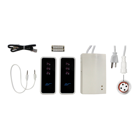
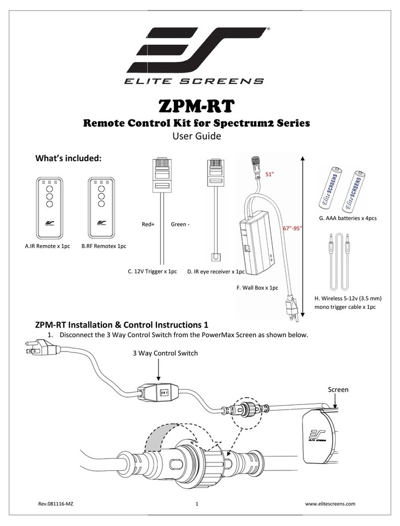
What’s included:
ZPM-RT3 accessories/parts list
A. IR Remote
ZRC1-IR
B. RF Remote
ZRC1-RF
C. Wall box
controller
ZRC1-WB
D. RJ50 Cable
ZRC1-RJ50
E. AAA batteries
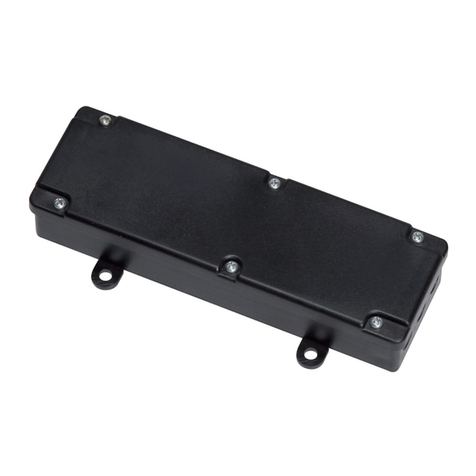
F. Circuit board housing
67”-95”
51”

Rev.V06282023JA (DS0267) 2 www.elitescreens.com
ZPM-RT3 Installation & Control Instructions
1. Disconnect the 3 Way Control In-line switch from the Spectrum 2 Screen as shown below.
3 Way Control In-line Switch
2. Connect the Circuit board housing (F) to the screen as shown below.
Circuit board housing (F)
Screen
Screen

Rev.V06282023JA (DS0267) 3 www.elitescreens.com
Screen operation
5 Ways to control your Spectrum 2 screen with ZPM-RT3
1. Wall box controller (Item C, Fig 3): The wall box controller switch is a wall mounted control box which can be
operated using the up/stop/down button. It plugs directly into RJ50 port of the circuit board housing.
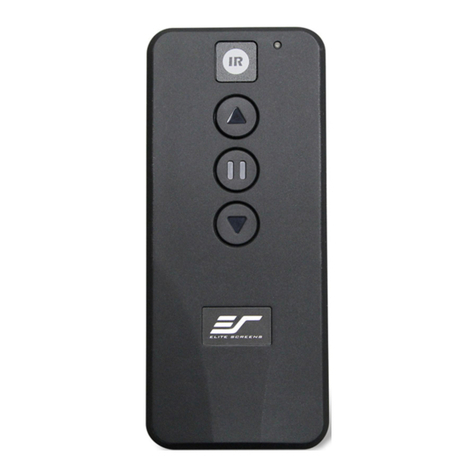
2. IR Remote control (Item A, Fig 1): The Infrared functions by direct line of sight
contact using an effective beam range of 25 feet within a 30-degree angle. Aim the
IR remote directly at the IR receiver on the Wall Box Controller to operate the screen.
Note: Assure there are no obstructions between the IR remote and IR receiver.
3. RF Remote Control (Item B): The radio waves eliminate the need for a direct line of sight and has a longer
distance control range.
Please follow the steps below to pair the RF remote to the wall box controller to operate your screen.
I. How to synchronize/pair a new RF remote:
•Press & hold the “Programming Key”, then press the “Up Key” on the Wall box controller (wall-box LED
flashes). Reference the wall box controller section for programming key location.
•Then press the “Up Key” on the RF remote.
The Wall box LED will flash 5 times, to indicate the RF remote has been properly synchronized/paired.
Wall box controller
IR Receiver
Wall box controller
SIDE VIEW
RJ50 PORT:
Connects to the
Screen RJ50 PORT
(RJ50 CABLE ONLY)
3.5mm mono Projector
Trigger Port (if Projector
equipped)
Wall box controller
BACK VIEW
Programming Key
RJ50 cable
LED light
UP
STOP
DOWN
Fig.1
IR/RF remote
IR Lens
Wall box controller
IR Receiver
RJ50 cable
IR remote
Circuit board housing

Rev.V06282023JA (DS0267) 4 www.elitescreens.com
II. How to change the RF code (For use when multiple screens/RF remotes are owned)
Changing the RF code avoids controlling multiple screens at the same time and prevents electrical interference
leading to accidental control of the screen.
1. Remove the batteries
2. Change the RF code switch
3. Insert the batteries
4. Synchronize it with the wall box controller
4. Wired 5-12 volt trigger: Requires a 3.5mm to 3.5mm mono cable (not included)
Step 1: Connect one end the RJ50 cable to the screen and the other end to the Wall box controller.
Step 2: Then connect one end the 3.5mm mono cable to the wall box controller and the other to the projector.
Once the two cables have been connected, the wired trigger feature is ready to synchronize the screen’s
up/down operation with the projector’s power cycle.
•Projector on, screen drops
•Projector off, screen raises
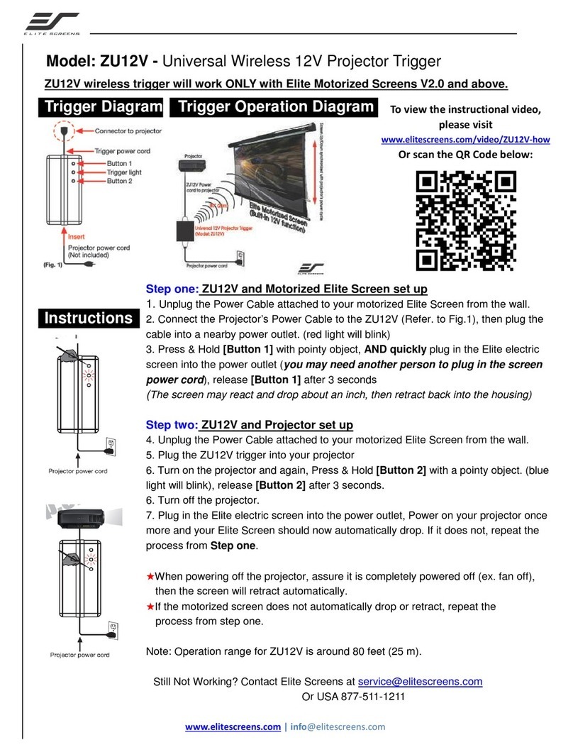
5. Wireless 5-12 volt trigger (Fig 5): Requires a 3.5mm to 3.5mm mono cable (not included).
The Radio Frequency (RF) remote control serves as a dual purpose, independently as a handheld remote control,
or as a Wireless 5-12 volt trigger. The radio frequency technology sends a wireless signal that synchronizes the
screen’s drop & rise with the projector’s power cycle.
Battery compartment
Default
“000”
RF Remote
BACK VIEW
Slide Switches
for RF Code
change
3.5 mm port
DC 5-12V out
3.5mm to 3.5mm mono cable
Wall box controller
RJ50 cable
Fig. 4
Projector
Mono 3.5mm
Projector Trigger
Port
Fig. 5
3.5 mm port
DC 5-12V out
3.5mm to 3.5mm mono cable
UP
STOP
DOWN
Projector
RF remote control
SIDE VIEW

Rev.V06282023JA (DS0267) 5 www.elitescreens.com
Here’s how to set up your Wireless 5-12 volt trigger
The 5-12V wireless trigger should already be synced and ready to work.
Step 1: Connect one end of the 3.5 mm mono trigger cable to the RF remote.
Step 2: Connect the other 3.5 mm mono end of the cable to your projector
Step 3: Turn on the projector and the screen should automatically deploy.
Step 4: Turn off your projector and the screen should automatically retract.
(Please be aware, the projector on/off cycle may take longer to fully activate. It usually takes around 20- 30 seconds
for full off and on cycle each time)
Note: If the wireless trigger feature does not work, please resync the RF remote to the Wall box controller per
the instructions in the Radio Frequency remote section.
ADVANCED Programming Key Instructions: (FOR ADVANCED USERS ONLY)
Note: Wall box controller must be connected to the screen.
1. Preset the Screen’s Drop Position:
Use the RF/IR remote or Wall Box Controller to Drop the screen to the desired position you want to set it at.
Press & hold the “Programming Key”, then press the “Down key” on the Wall Box Controller. The LED will flash 5 times
to confirm the new programmed drop position.
2. Clear/Reset the Screen’s Drop Position to factory default: Press & hold the “Programming Key + “Stop key”
on the wall box controller.
For a local Elite Screens contact or Technical Support, please visit
www.elitescreens.com
ATTENTION: Reducing the factory’s full screen drop may produce waves/wrinkles on the projection surface on
tab-tension screens. The full drop is recommended to allow the screen to rely on the tab-tension system to
maintain the projection surface flat and taut on all sides.
The same applies on non-tensioned screens, although some level of waves may be present due to the nature
of the screen not being tensioned. If wrinkles/waves develop after making the adjustment to the desired drop
position, reset it to the factory’s default position per the instructions below.
FLATNESS AFFECTED BY NEW PROGRAMMED VERTICAL POSITION IS NOT COVERED UNDER A REPLACEMENT
WARRANTY.
PROGAMMING NOTE:
The programmed vertical position relies on a time-count which adjusts itself according to the programmed
timed difference. Multiple up/down programming will result in the vertical position being off a few inches. It is
recommended that programming is done the first-time the desired vertical position is determined or RESET it to
factory default and programming the desired vertical position afterwards.
Table of contents
Other Elite Screens Remote Control manuals
