ELCART 09/07800-00 NI2100 User manual

ELCART
ELCART DISTRIBUTION SPA via Michelangelo Buonarroti, 46 - 20093 Cologno Monzese (Milano) ITALY
Manuale di istruzioni/Scheda tecnica
La divulgazione dei dati contenuti in questa scheda è da ritenersi un servizio puramente informativo e non costituisce alcun vincolo da parte della Elcart in merito a prestazioni ed utilizzo del prodotto.
The divulgation of data contained on this technical sheet are exclusively for informational reasons and establish no link on behalf of Elcart regard to thr performances and the usa of the product.
La divulgacion de los datos contenidos en esta ficha son un servicio unicamente informativo y no constituyen ningun vinculo de parte de Elcart respecto a las prestaciones y uso del producto.
ART. 09/07800-00 PAGINA 1 DI 4
1- Display LCD: cifre da 3½ digit, carattere alto 15mm
2- Pulsante di Retroilluminazione: premere questo pulsante per
accendere la retroilluminazione se la situazione della luce rendesse
difcileeseguirelamisurazione;lalucesispegneràautomaticamente
dopo 5 secondi. Premerla di nuovo per riaccenderla.
Selabatteriaèscarica,lalucesaràattenuata.
3- Commutatore Rotante: usate questo commutatore per selezionare le
funzioni e le portate
4- TerminalediIngressodiVΩmA
5- Terminale di Ingresso COM
6- TerminalediIngressoda10A
7- Commutatore per il mantenimento dei dati (HOLD)
3. Informazioni di Sicurezza
3-1GlistrumentisonoprogettatiinconformitàallenormeIEC-61010
relative agli strumenti di misura elettronici con una categoria di
sovratensione(CATIII)edinquinamento2.
3-2 Seguite tutte le istruzioni di sicurezza ed operative per assicurare che
lo strumento sia usato in modo sicuro e sia tenuto in buone condizioni
operative.
3-3 Simboli di sicurezza:
Informazione importante di sicurezza, riferirsi al manuale di
funzionamento
Vi può essere la presenza di una tensione pericolosa
Doppio isolamento (protezione di Class II)
4. Precauzioni Speciali per il Funzionamento
4-1 Gli strumenti sono sicuri in base a procedure standard quando
sono usati con i puntali in dotazione.
Sostituire i puntali danneggiati solo con quelli dello stesso modello o
aventi le stesse caratteristiche tecniche.
4-2 Per evitare il rischio di scosse elettriche, non usare lo strumento
senza copertura.
4-3 Il commutatore di portata deve essere in posizione corretta per la
prova.
4-4 Per evitare scosse elettriche e danneggiare gli strumenti, i segnali di
ingresso non devono superare i limiti indicati.
4-5 Quando si misura un apparecchio TV o una tensione commutata,
prestare attenzione ai possibili impulsi che possono distruggere il
circuito.
4-6 Durante la misura è proibito variare a caso la posizione del
commutatore di portata.
4-7Attenzioneallescossedurantelamisuraditensionimaggioridi
60VCC&30VCA.
4-8 Il fusibile di protezione deve essere sostituito solo con uno dello
stesso tipo e con le stesse caratteristiche tecniche.
5. Caratteristiche tecniche generali
5-1MaxtensionetrailmorsettodiingressoelaTerra:CATIII600V
5-2 Indicazione di fuori portata: display 1 per la cifra significativa
5-3Displayautomaticodellapolaritànegativa"-"
1. Generalità
Multimetro portatile caratterizzato da una forma sottile, prestazioni stabili e
guscio anti-caduta. Grazie ad un display 3 ½ digit LCD con carattere alto
15mm, esso fornisce letture chiare. Per via della progettazione circuitale
generalebasatasuiconvertitoriA/DeICalargascalainsiemeaicircuiti
di sovraccarico e di protezione, produce una eccellente prestazione come
strumento di misura pratico.
PuòessereusatopermisuraretensioniCC&CA,correnteCC,resistenza,
cadutaditensionedeldiodopositivaecontinuità.
2. Disposizione del Pannello
MULTIMETRO DIGITALE ART. 09/07800-00 NI2100
MANUALE DI ISTRUZIONI
5-4IndicazionediBatteriaScarica:""visualizzata
5-5 Max display a LCD: 1999 (3½ cifre)
5-6Protezionedelfusibile: F-250mA/600V(Ø5x20mm)
5-7Alimentazione: batteriada9V,6F22oNEDA1604
5-8TemperaturadiFunzionamento: 0°Ca40°C(umiditàrelativa<85%)
5-9TemperaturadiDeposito: -10°Ca50°C(umiditàrelativa<85%)
5-10 Temperatura in cui è garantita la precisione: 23±5°C
(umiditàrelativa<85%)
5-11 Dimensione: 69x138x31mm (con fodero)
5-12 Peso: circa 170gr. (compresa la batteria)
6. Caratteristiche tecniche di prova
La Precisione si riferisce al periodo di un anno dopo la taratura e da 18°C
a28°C(da64°Fa82°F)conumiditàrelativadel75%
6-1 Tensione CC
Portata Risoluzione Precisione
200mV 0,1mV ±(0,5%dellalettura±3cifre)
2V 1mV ±(0,5%dellalettura±3cifre)
20V 10mV ±(0,5%dellalettura±3cifre)
200V 100mV ±(0,5%dellalettura±3cifre)
600V 1V ±(0,8%dellalettura±3cifre)
Portata Risoluzione Precisione
20µA 0,01µA ±(1,0%dellalettura±3cifre)
200µA 0,1µA ±(1,0%dellalettura±3cifre)
2mA 1µA ±(1,0%dellalettura±3cifre)
20mA 10µA ±(1,0%dellalettura±5cifre)
200mA 100µA ±(1,0%dellalettura±5cifre)
10A 10mA ±(1,0%dellalettura±10cifre)
Portata Risoluzione Precisione
200Ω 0,1Ω ±(0,8%dellalettura±5cifre)
2KΩ 1Ω ±(0,8%dellalettura±2cifre)
20KΩ 10Ω ±(0,8%dellalettura±2cifre)
200KΩ 100Ω ±(0,8%dellalettura±2cifre)
2MΩ 1KΩ ±(1,0%dellalettura±5cifre)
Portata Risoluzione Precisione
200V 100mV ±(1,2%dellalettura±10cifre)
600V 1V ±(1,2%dellalettura±10cifre)
-impedenzadiingresso: 1MΩ
- Protezione di Sovraccarico: 600V per la portata di 200mV,
DCefficaceoAC600Vperaltreportate
6-2 Tensione CA
- Portata di Frequenza: da 40 da 400Hz
- Risposta: media, tarata in rms sull'onda sinusoidale
6-3 Corrente CC
-ProtezionediSovraccarico: fusibiledaF200mA/600V
Nota:
(1)portatada10A:senzafusibile(2)portatada200µAèsoloperArt.9/7850
6-4 Resistenza
-ProtezionediSovraccarico: 600Vdivaloreefcace
Portata Risoluzione Funzione
1mV Visualizza il valore approssimativo della
caduta di tensione diretta del diodo
Portata Funzione
Ilcicalinoincorporatosuoneràselaresistenzaè
inferiorea50Ω
6-5 Prova del Diodo
6-6 Continuità
-ProtezionediSovraccarico: 600Vvaloreefcace
-CorrentedirettaCC: circa1mA
- Tensione inversa CC: circa 3,0V
-ProtezionediSovraccarico: 600Vvaloreefcace
- Tensione a circuito aperto: circa 3.0V
1
7
6
4
3
2
5

ELCART
ELCART DISTRIBUTION SPA via Michelangelo Buonarroti, 46 - 20093 Cologno Monzese (Milano) ITALY
Manuale di istruzioni/Scheda tecnica
La divulgazione dei dati contenuti in questa scheda è da ritenersi un servizio puramente informativo e non costituisce alcun vincolo da parte della Elcart in merito a prestazioni ed utilizzo del prodotto.
The divulgation of data contained on this technical sheet are exclusively for informational reasons and establish no link on behalf of Elcart regard to thr performances and the usa of the product.
La divulgacion de los datos contenidos en esta ficha son un servicio unicamente informativo y no constituyen ningun vinculo de parte de Elcart respecto a las prestaciones y uso del producto.
ART. 09/07800-00 PAGINA 2 DI 4
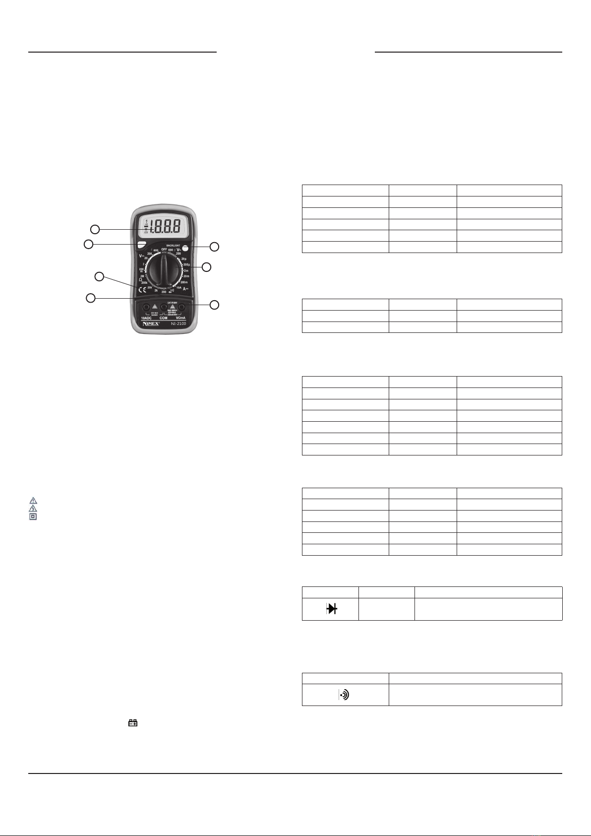
7. ISTRUZIONI OPERATIVE
7-1 Precauzioni da seguire prima del funzionamento
7-1-1 Controllare la batteria da 9V. Se la tensione della batteria è
inferiorea7V,ildisplaymostrerà"",aquestopuntolabatteria
deve essere cambiata per garantire la precisione della misura.
7-1-2Porreattenzionealsegno""postoaccantoalterminaledi
ingresso, che indica che la tensione o corrente di ingresso non
devesuperareilvalorespecicato.
7-1-3 Il commutatore di portata deve essere posto alla portata prescelta
per la misura prima del funzionamento.
7-2 Misurare la Tensione VCC
7-2-1Inserireilpuntaleneronelterminale"COM"equellorossonel
terminale"VΩmA".
7-2-2 Porre il commutatore rotante alla posizione di portata desiderata V
7-2-3 Collegare i puntali all'apparecchiatura da misurare.
7-2-4 La lettura viene visualizzata sul display LCD.
Lapolaritàdelcollegamentodelpuntalerossosaràindicata
insieme al valore della tensione.
NOTA:
1. Quando non si conosce prima la scala di misura, porre il selettore di
portata nella posizione più alta.
2.Quandoèvisualizzatasololacifra"1"o"-1",ciòindicaunasituazione
di fuori-portata e deve essere selezionata la portata più alta.
3.""indicachenonsipuòporrelatensionediingressosuperiorea
600V, è possibile indicare una tensione più alta, ma può distruggere il
circuito interno o provocare una scossa.
4.Attentiallescossequandosimisuraun'altaTensione.
7-3 Misurare la Tensione VCA
7-3-1Inserireilpuntaleneronelterminale"COM"equellorossonel
terminale"VΩmA".
7-3-2 Porre il commutatore rotante nella posizione di portata desiderata V~
7-3-3 Collegare i puntali all'apparecchiatura da misurare.
7-3-4 La lettura viene visualizzata sul display LCD.
NOTA:
1. Quando non si conosce prima la scala di misura, porre il selettore di
portata nella posizione più alta.
2.Quandoèvisualizzatasololacifra"1"o"-1",ciòindicaunasituazione
di fuori-portata e deve essere selezionata la portata più alta.
3.""indicachenonsipuòporrelatensionediingressosuperiorea
600V, è possibile indicare una tensione più alta, ma può distruggere il
circuito interno o provocare una scossa.
4. Attentiallescossequandosimisuraun'altaTensione.
7-4 Misurare Corrente CC
7-4-1Inserireilpuntaleneronelterminale"COM"equellorossonel
terminale"VΩmA"perunacorrentemassimadi200mA,
oppurenelterminale"10A"perunacorrentemassimadi10A.
7-4-2PorreilcommutatorerotanteallaposizionediportatadesiderataA
7-4-3 Interrompete il circuito collegando in serie i puntali.
7-4-4 La lettura viene visualizzata sul display LCD.
Lapolaritàdelcollegamentodelpuntalerossosaràindicatainsieme
al valore di corrente.
NOTA:
1. Quando non si conosce prima la scala di misura, porre il selettore di
portata nella posizione più alta.
2.Quandoèvisualizzatasololacifra"1"o"-1",ciòindicaunasituazione
di fuori-portata e deve essere selezionata la portata più alta.
3.""indicalacorrentemassimadellapresa(200mAe10A),percuila
sovracorrentedistruggeràilfusibile.
Datoche10Anonèdotatadifusibile,iltempodimisuradeveessere
inferiore ad 1 secondo per evitare che la precisione venga influenzata
dal riscaldamento del circuito.
7-5 Misurare la Resistenza
7-5-1Inserireilpuntaleneronelterminale"COM"equellorossonel
terminale"VΩmA".
7-5-2PorreilcommutatorerotantesullaposizionediportataΩdesiderata.
7-5-3 Collegare i puntali all'apparecchiatura da misurare
7-5-4 La lettura viene visualizzata sul display LCD.
NOTA:
1. Quandoèvisualizzatasololacifra"1"o"-1",ciòindicaunasituazione
di fuori-portata e si deve selezionare la portata più alta.
2. Permisurareunaresistenzasuperiorea1MΩ,lostrumentopuò
impiegare alcuni secondi per dare una lettura stabile.
3. Quandol'ingressononècollegato,ades.acircuitoaperto,lacifra"1"
saràvisualizzataperlacondizionedisovraportata.
4. Quando si controlla la resistenza interna del circuito, assicurarsi che
tutta l'alimentazione sia esclusa dal circuito sotto prova e che tutti i
condensatori siano stati completamente scaricati.
5. Se la scala del valore da misurare non si conosce prima, porre il
selettore di portata nella posizione più alta.
7-6 Prova del Diodo
7-6-1Inserireilpuntaleneronelterminale"COM"equellorossonel
terminale"VΩmA",(lapolaritàdelterminalerossoè"+")
7-6-2 Porre il commutatore rotante nella posizione di portata .
7-6-3 Collegare il puntale rosso all'anodo e quello nero al catodo del
diodo sotto misura.
7-6-4 La lettura viene visualizzata sul display LCD.
NOTA:
1. Lostrumentoindicheràil valore approssimativo della caduta di
tensione diretta del diodo.
2. Seilcollegamentoalterminaleèinvertito,saràvisualizzatosolo"1".
7-7 Prova di Continuità
7-7-1Inserireilpuntaleneronelterminale"COM"equellorossonel
terminale"VΩmA".
7-7-2 Porre il commutatore rotante nella posizione di portata .
7-7-3 Collegare i puntali tra due punti del circuito sotto prova.
7-7-4Seviècontinutià(ades.resistenzainferiorea50Ω),suoneràil
cicalino incorporato.
NOTA:
Nelcasodicircuitodiingressoaperto,saràvisualizzatalacifra"1".
8. Manutenzione
8-1 Prima di cercare di togliere lo sportello delle batterie o di aprire la
custodia, assicurarsi che i puntali siano stati scollegati dal circuito di
misura per evitare il rischio di scosse elettriche.
8-2 Per evitare scosse elettriche, togliere i puntali dai circuiti di
misura prima di sostituire il fusibile. Per la protezione da incendi,
sostituireifusibiliconquellidivalorispecificati:fusibileF-250mA/600V
8-3 Sostituire i puntali se i terminali sono scoperti, ed utilizzare puntali che
abbiano le stesse caratteristiche tecniche di quelli originali.
8-4Usaresolotessutoumidoepiccolequantitàdidetergentemanon
usare soluzioni chimiche per la pulizia.
8-5Nonusarelostrumentoprimachelacoperturaposterioresiachiusa
adeguatamente ed avvitata. In caso di qualsiasi anomalia, sospendete
immediatamente ogni operazione ed inviate lo strumento ad un centro
di assistenza.
9. Accessori
(1)Puntali:valorielettrici1000V10A
(2)Batteria:9V,6FF22oNEDA1604
(3)Fusibile:F-250mA/600V
(4) Manuale dell'Operatore
(5) Custodia antiurto.
Made in China
Informazione agli utenti ex art. 26 D.Lgs. 49/2014
Il simbolo riportato sull’apparecchiatura (Allegato IX D.Lgs. 49/2014)
indica che il riuto deve essere oggetto di “raccolta separata” e che è stato
immesso sul mercato, in Italia, dopo il 31/12/2010. Pertanto, l’utente
dovrà conferire (o far conferire) il riuto ai centri di raccolta dierenziata
predisposti dalle amministrazioni locali, oppure consegnarlo al rivenditore
contro acquisto di una nuova apparecchiatura di tipo equivalente.
L’utente ha dunque un ruolo attivo: la raccolta dierenziata del riuto e le
successive operazioni di trattamento, recupero e smaltimento favoriscono
la produzione di apparecchiature con materiali riciclati e limitano gli eetti
negativi sull’ambiente e sulla salute eventualmente causati da una gestione
impropria del riuto. Nel caso di RAEE di piccolissime dimensioni
(<25 cm), l’utente ha diritto al conferimento gratuito, senza obbligo di
contestuale acquisto, ai distributori al dettaglio la cui supercie di vendita
specializzata eccede i 400 mq.
IMPORTATO E DISTRIBUITO DA
ELCART DISTRIBUTION SPA
Via Michelangelo Buonarroti, 46
20093 COLOGNO MONZESE (MI)
ITALY
www.elcart.com - [email protected]

ELCART
ELCART DISTRIBUTION SPA via Michelangelo Buonarroti, 46 - 20093 Cologno Monzese (Milano) ITALY
Manuale di istruzioni/Scheda tecnica
La divulgazione dei dati contenuti in questa scheda è da ritenersi un servizio puramente informativo e non costituisce alcun vincolo da parte della Elcart in merito a prestazioni ed utilizzo del prodotto.
The divulgation of data contained on this technical sheet are exclusively for informational reasons and establish no link on behalf of Elcart regard to thr performances and the usa of the product.
La divulgacion de los datos contenidos en esta ficha son un servicio unicamente informativo y no constituyen ningun vinculo de parte de Elcart respecto a las prestaciones y uso del producto.
ART. 09/07800-00 PAGINA 3 DI 4
1
7
6
4
3
2
5
1. LCD Display: 3 ½ digits, character 15mm high
2. Light Button Switch> Press this button to swtch on back light if the dark
circumstancelightmakesthereadingdifcultywhenmeasuring,the
light will be automatically turned off in 5 seconds. Press again to switch
it on again. If the battery is in weak power, the light will be dimmed.
3. Rotary Switch: use this switch to select functions and ranges
4.VΩmAInputJack
5.COMInputJack
6.Ω10AInputJack
7. Data-hold Switch (HOLD)
3. Safety Information
3-1ThemetersaredesignedaccordingtoIEC-61010concerningelectronic
measuringinstrumentswithanover-voltagecategory(CATIII)and
pollution 2.
3-2 Follow all safety and operating instructions to ensure that the meter is
used safely and is kept in good operating condition.
3-3 Safety symbols:
Important safety information, refer to the operating manual.
Dangerous voltage may be presence.
Double insulation (protection Class II)
4. Special Cautions for Operation
4-1 The meters can be safe only according to standard procedures when
used in conjunctions with the supplied test leads. To replace damaged
test leads with only the same model or same electric specifications.
4-2 To avoid risk of electric shock, do not use the meters before the cover
is in place.
4-3 The range switch should be right position for the testing.
4-4 To avoid electric shock and damaging the instruments, the input
signals are forbidden to exceed the specified limits.
4-5 When measuring TV set or switched power, attention should be paid
to the possible pulses that may bring destruction to the circuit.
4-6 Range switch position is forbidden to be changed at random during
measurement.
4-7 Take caution against shock in the course of measuring voltage higher
thanDC60V&AC30V.
4-8 Protection fuse should be replaced only with same type and same
specification.
5. GENERAL SPECIFICATIONS
5-1MaxVoltagebetweeninputterminalandEarthGround:CATIII600V
5-2 Over-range Indication: display “1” for the significant digit.
5-3Automaticdisplayofnegativepolarity“-”.
5-4 Low Battery Indication: ‘ ’ displayed
5-5 Max LCD display: 1999 (3 ½ digits)
5-6Fuseprotection: F-250mA/600V(Ø5x20mm)
5-7PowerSupply: 9Vbattery,6F22orNEDA1604
5-8Operatingtemperature: 0°Cto40°C(relativehumidity<85%)
1. Overview
The multimeter is characterized at slim size, portable, stable performance
and anti-dropping capacity. Using 3 ½ digits LCD monitor with character
15mm high, they offer clear readings. With overall circuitry design centering
onlarge-scale ICA/Dconvertersin conjunctionand over-loadprotection
circuit, the meters give excellent performance and exquisite making as a
handy utility instrument.
The meters can be used to measure AC & DC voltage, DC current,
resistance, positive diode voltage fall and continuity.
2. Panel Layout
DIGITAL MULTIMETER ART. 09/07800-00 NI2100
OPERATION MANUAL
5-9 Storagetemperature: -10°Cto50°C((relativehumidity<85%)
5-10Guaranteedprecisiontemperature:23±5°C(relativehumidity<85%)
5-11 Dimensions: 69x138x31mm (with holster)
5-12 Weight: approx 170gr. (including battery)
6. Testing Specifications
Accuracyisspecifiedforaperiodofyearaftercalibrationandat18°Cto
28°C(64°Fto82°F)withrelativehumidityto75%.
6-1 DC Voltage
Range Resolution Accuracy
200mV 0,1mV ±(0.5%ofrdg±3digits)
2V 1mV ±(0,5%ofrdg±3digits)
20V 10mV ±(0,5%ofrdg±3digits)
200V 100mV ±(0,5%ofrdg±3digits)
600V 1V ±(0,8%ofrdg±3digits)
Range Resolution Accuracy
20µA 0,01µA ±(1,0%ofrdg±3digits)
200µA 0,1µA ±(1,0%ofrdg±3digits)
2mA 1µA ±(1,0%ofrdg±3digits)
20mA 10µA ±(1,0%ofrdg±5digits)
200mA 100µA ±(1,5%ofrdg±5digits)
10A 10mA ±(3,0%ofrdg±10digits)
Range Resolution Accuracy
200Ω 0,1Ω ±(0,8%ofrdg±5digits)
2KΩ 1Ω ±(0,8%ofrdg±2digits)
20KΩ 10Ω ±(0,8%ofrdg±2digits)
200KΩ 100Ω ±(0,8%ofrdg±2digits)
2MΩ 1KΩ ±(1,0%ofrdg±5digits)
Range Resolution Accuracy
200V 100mV ±(1,2%ofrdg±10digits)
600V 1V ±(1,2%ofrdg±10digits)
-InputImpendence: 1MΩ
- Overload protection: 600V for 200mV range,
effectiveDCorAC600Vforotherranges
- Frequency Range: 40 to 400Hz
- Response: average, calibrated in rms of sine wave
- over-load protection: 600V effective value
6-4 Resistenza
6-3 DC Current
6-2 AC Voltage
Range Resolution Function
1mV Display: read approximate forward
voltage of diode
Range Function
Built-in buzzer will sound if resistance is lower
than50Ω
6-5 Diode Test
6-6 Continuity
- over-load Protection: 600V effective value
-forwardDCcurrent:approximate1mA
- Reversed DC voltage: approximate 3.0V
- over-load protection: 600V effective value
- open circuit voltage: approximate 3.0V

ELCART
ELCART DISTRIBUTION SPA via Michelangelo Buonarroti, 46 - 20093 Cologno Monzese (Milano) ITALY
Manuale di istruzioni/Scheda tecnica
La divulgazione dei dati contenuti in questa scheda è da ritenersi un servizio puramente informativo e non costituisce alcun vincolo da parte della Elcart in merito a prestazioni ed utilizzo del prodotto.
The divulgation of data contained on this technical sheet are exclusively for informational reasons and establish no link on behalf of Elcart regard to thr performances and the usa of the product.
La divulgacion de los datos contenidos en esta ficha son un servicio unicamente informativo y no constituyen ningun vinculo de parte de Elcart respecto a las prestaciones y uso del producto.
ART. 09/07800-00 PAGINA 4 DI 4
7. OPERATING INSTRUCTIONS
7-1 Attention before operation
7-1-1 Check 9V battery. If the battery voltage is less than 7V, display will
show “ ”, the battery should be replaced at this time to ensure mea-
suring precision.
7-1-2 Pay attention to the “ ” besides the input jack which shows that the
input voltage or current should be within the specified value.
7-1-3 The range switch should be positioned to desired range for measu-
rement before operation.
7-2 Measuring DC Voltage
7-2-1ConnecttheblacktestleadtoCOMjackandtheredtoVΩmAjack.
7-2-2 Set the rotary switch at the desired V range position.
7-2-3 Connect test leads across the source or load under measurement.
7-2-4 You can get reading from LCD. The polarity of the red lead connec-
tion will be indicated along with the voltage value.
NOTE:
1. When the value scale to be measured is unknown beforehand, set the
range selector at the highest position.
2. When only the figure’1’ or ‘-1’ is displayed, it indicates over-range situa-
tion and the higher range has to be selected.
3. “ ” means you can’t input the voltage more than 600V, it’s possible
to show higher voltage, but it may destroy the inner circuit or pose a
shock.
4.Be cautious against shock when measuring high Voltage.
7-3 Measuring AC Voltage
7-3-1ConnecttheblacktestleadtoCOMjackandtheredtoVΩmAjack.
7-3-2 Set the rotary switch at the desired V~ range position.
7-3-3 Connect test leads across the source or load under measurement.
7-3-4 You can get reading from LCD.
NOTE:
1. When the value scale to be measured is unknown beforehand, set the
range selector at the highest position.
2. When only the figure’1’ or ‘-1’ is displayed, it indicates over-range situa-
tion and the higher range has to be selected.
3. “ ” means you can’t input the voltage more than 600V, it’s possible to
show higher voltage, but it may destroy the inner circuit or pose a shock.
4. Be cautious against shock when measuring high Voltage.
7-4 Measuring DC Current
7-4-1ConnecttheblacktestleadtoCOMjackandtheredtotheVΩmA
jack for a maximum 200mA current, for a maximum 10A current,
movetheredleadtothe10Ajack.
7-4-2SettherotaryswitchatthedesiredArangeposition.
7-4-3 Connect test leads in series with the load under measurement.
7-4-4 You can get reading from LCD. The polarity of the red lead connec-
tion will be indicated along with the current value.
NOTE:
1. When the value scale to be measured is unknown beforehand, set the
range selector at the highest position.
2. When only the figure’1’ or ‘-1’ is displayed, it indicates over-range situa-
tion and the higher range has to be selected.
3.“”meansthesocketmA’smaximumcurrentis200mAand10A’sma-
ximumcurrentis10A,over currentwilldestroythefuse. Since10Ais
not fused, the measuring time should be less than 1 second to prevent
precision from affecting by circuit heating.
7-5 Measuring Resistance
7-5-1ConnecttheblacktestleadtoCOMjackandtheredtoVΩmAjack.
7-5-2SettherotaryswitchatthedesiredΩrangeposition.
7-5-3 Connect test leads across the resistance under measurement.
7-5-4 You can get reading from LCD.
NOTE:
1. When only the figure’1’ or ‘-1’ is displayed, it indicates over-range situa-
tion and the higher range has to be selected.
2.Formeasuringresistanceabove1MΩ,themetemaytakeafewseconds
to get stable reading.
3. When the input is not connected, i.e. at open circuit, the figure ‘1’ will be
displayed for the over-range condition.
4. When checking in-circuit resistance, be sure the circuit under test has
all power removed and that all capacitors have been discharged fully.
5. The value scale to be measured is unknown beforehand, set the range
selector at the highest position.
7-6 Diode Testing
7-6-1ConnecttheblacktestleadtoCOMjackandtheredtoVΩmAjack.
(thepolarityofredleadis‘+’)
7-6-2 Set the rotary switch at the range position.
7-6-3 Connect the red lead to the anode and the black lead to the cathode
of the diode under testing.
7-6-4 You can get a reading from LCD.
NOTE:
1. The meter will show approximate forward voltage drop of the diode.
2. If the lead connections is reversed, only ‘1’ will be displayed.
7-7 Continuity Testing
7-7-1ConnecttheblacktestleadtoCOMjackandtheredtoVΩmAjack.
7-7-2 Set the rotary switch at the range position.
7-7-3 Connect test leads across two points of the circuit under testing.
7-7-4Ifcontinuityexists(i.e.resistancelessthanabout50Ω),
built-in buzzer will sound.
NOTE:
If the input open circuit, the figure ‘1’ will be displayed.
8. Maintenance
8-1 Before attempting to remove the battery door or open the case, be sure
that test leads have been disconnected from measurement circuit top
avoid electric shock hazard.
8-2 To avoid electrical shock, remove test leads from measurement circuits
before replacing the fuse. For protection against fire, replace fuses only
withspecifiedratings:F-250mA/600Vfuse.
8-3 Your must replace the test leads if the lead is exposed, and should
adopt the leads with the same specifications as origin.
8-4 Use only moist fabric or small amount of detergent but not chemical
solution for cleaning.
8-5 do not use the meter before the back cover is properly closed and
screw secured. Upon any abnormality, stop operation immediately and
send the meter for maintenance.
8-6 Please take out the battery when not using for a long time.
9. Accessories
(1)TestLeads:electricrating1000V10A
(2)Battery:9V,6F22orNEDA1604
(3)Fuse:F-250mA/600V
(4) Operator’s Manual
(5) Holster
User information ex art. 26 D. 49/2014
The symbol labelled on the appliance (Annex IX D. 49/2014) indicates that
the rubbish is subject to “separate collection” and it has been placed on the
Italian market after the December 31, 2010.
The user must therefore assign or (have collected) the rubbish to a
treatment facility according to indications by the local administration, or
hand it over to the reseller in exchange for an equivalent new product. The
separate collection of the rubbish and the subsequent treatment, recycling
and disposal operations encourage the production of appliances made
with recycled materials and reduce negative eects on health and the
environment caused by improper treatment of rubbish.
In the case of very small WEEE (no external dimension more than 25 cm),
the user is eligible to get free of charge assignation to retail shops with sales
areas relating to EEE of at least 400 m².
Made in China
IMPORTED AND DISTRIBUTED BY:
ELCART DISTRIBUTION SPA
Via Michelangelo Buonarroti, 46
20093 COLOGNO MONZESE (MI)
ITALY
www.elcart.com - [email protected]
Table of contents
Languages:
Other ELCART Multimeter manuals