manuals.online logo
Brands
  1. Home
  2. •
  3. Brands
  4. •
  5. ELCART
  6. •
  7. Multimeter
  8. •
  9. ELCART NI 2100 User manual

ELCART NI 2100 User manual

ELCART
ELCART DISTRIBUTION SPA via Michelangelo Buonarroti, 46 - 20093 Cologno Monzese (Milano) ITALY
Tel. +39 02.25117310 Fax +39 02.25117610 sito internet: www.elcart.com e-mail: [email protected]
Manuale di istruzioni/Scheda tecnica
La divulgazione dei dati contenuti in questa scheda è da ritenersi un servizio puramente informativo e non costituisce alcun vincolo da parte della Elcart in merito a prestazioni ed utilizzo del prodotto.
The divulgation of data contained on this technical sheet are exclusively for informational reasons and establish no link on behalf of Elcart regard to thr performances and the usa of the product.
La divulgacion de los datos contenidos en esta ficha son un servicio unicamente informativo y no constituyen ningun vinculo de parte de Elcart respecto a las prestaciones y uso del producto.
ART. 9/7800 PAGINA 1 DI 4
ELCART
ELCART DISTRIBUTION SPA via Michelangelo Buonarroti, 46 - 20093 Cologno Monzese (Milano) ITALY
Tel. +39 02.25117310 Fax +39 02.25117610 sito internet: www.elcart.com e-mail: [email protected]
Manuale di istruzioni/Scheda tecnica
La divulgazione dei dati contenuti in questa scheda è da ritenersi un servizio puramente informativo e non costituisce alcun vincolo da parte della Elcart in merito a prestazioni ed utilizzo del prodotto.
The divulgation of data contained on this technical sheet are exclusively for informational reasons and establish no link on behalf of Elcart regard to thr performances and the usa of the product.
La divulgacion de los datos contenidos en esta ficha son un servicio unicamente informativo y no constituyen ningun vinculo de parte de Elcart respecto a las prestaciones y uso del producto.
ART. 9/7800 PAGINA 2 DI 4
ELCART
ELCART DISTRIBUTION SPA via Michelangelo Buonarroti, 46 - 20093 Cologno Monzese (Milano) ITALY
Tel. +39 02.25117310 Fax +39 02.25117610 sito internet: www.elcart.com e-mail: [email protected]
Manuale di istruzioni/Scheda tecnica
La divulgazione dei dati contenuti in questa scheda è da ritenersi un servizio puramente informativo e non costituisce alcun vincolo da parte della Elcart in merito a prestazioni ed utilizzo del prodotto.
The divulgation of data contained on this technical sheet are exclusively for informational reasons and establish no link on behalf of Elcart regard to thr performances and the usa of the product.
La divulgacion de los datos contenidos en esta ficha son un servicio unicamente informativo y no constituyen ningun vinculo de parte de Elcart respecto a las prestaciones y uso del producto.
ART. 9/7800 PAGINA 3 DI 4
DIGITAL MULTIMETER ART. 9/7800 NI 2100
OPERATION MANUAL
1. Overview
The multimeter is characterized at slim size, portable, stable performance
and anti-dropping capacity. Using 3½ digits LCD monitor with character
15mm high, they offer clear readings. With overall circuitry design
centering on large-scale IC A/D converters in conjunction and over-load
protection circuit, the meters give excellent performance and exquisite
making as a handy utility instrument.
The meters can be used to measure DC & AC voltage, DC current,
resistance, positive diode voltage fall, hFE parameters for transistor and
Continuity.
2. Panel Layout
LCD Display: 3½ digits, character 15MM high
VΩ
mA Input Jack
10A Input Jack
COM Input Jack
3. Safety Information
3-1 The meters are designed according to IEC-1010 concerning electronic
measuring instruments with an over-voltage category (CAT II) and pollution
2.
3-2 Follow all safety and operating instructions to ensure that the meter is
used safely and is kept in good operating condition.
3-3 safety symbols:
important safety information, refer to the operating manual.
Dangerous voltage may be presence.
Double insulation (protection Class II)
4. Special Cautions for Operation
4-1 The meters can be safe only according to standard procedures when
used in conjunctions with the supplied test leads. To replace damaged test
leads with only the same model or same electric specifications.
4-2 To avid risk of electric shock, do not use the meters before the cover is
in place.
4-3 The range switch should be right position for the testing.
4-4 To avoid electric shock and damaging the instruments, the input
signals are forbidden to exceed the specified limits.
4-5 When measuring TV set or switched power, attention should be paid
to the possible pulses that may bring destruction to the circuit.
4-6 Range switch position is forbidden to be changed at random during
measurement.
4-7 Take caution against shock in the course ot measuring voltage higher
than DC 60V & AC 30V.
4-8 Protection fuse should be replaced only with same type and same
specification.
5. GENERAL SPECIFICATIONS
5-1 Max Voltage between input terminal and Earth Ground: CAT II 600V
5-2 Over-range Indication: display “1” for the significant digit.
5-3 Automatic display of negative polarity “_” .
5-4 Low Battery Indication: ‘ ’ displayed
5-5 Max LCD display: 1999 (31/2 digits)
5-6 Fuse protection: F-200mA/250V (Ø5x20MM)
5-7 Power Supply: 9V battery, 6F22 or NEDA 1604
5-8 Operating Temp.: 0℃ to 40℃ (relative humidity <85%)
5-9 Storage Temp.:-10℃ to 50℃ ((relative humidity <85%)
5-10 Guaranteed precision Temp.: 23±5℃ (relative humidity <85%)
5-11 Dimension: 69x138x31MM (with holster)
5-12 Weight: approx. 170g (including battery)
6. Testing Specifications
Accuracy is specified for a period of year after calibration and at 18℃ to 28
℃ (64℉ to 82℉) with relative humidity to 75%.
6-1 DC Voltage
range resolution accuracy
200mV 0.1mV ±(0.5% of rdg +7 digits )
2V 1mV ±(0.5% of rdg +7 digits)
20V10mV±(0.5% of rdg +7 digits)
200V 100mV ±(0.8% of rdg + 7 digits)
600V 1V ±(1.0% of rdg + 7 digits)
-- Input Impendence: 1MΩ
- Overload protection: 250V for 200mV range, effective DC or AC 600V for
other ranges
6-2 AC Voltage
range resolution accuracy
200V 100mV ±(1.2% of rdg + 10 digits)
600V 1V ±(1.2% of rdg + 10 digits)
-- Frequency Range: 40 to 400Hz
-- Response: average, calibrated in rms of sine wave
6-3 DC Current
range Resolution accuracy
200μA0.1μA±(1.0% of rdg + 2 digits)
2mA 1μA±(1.0% of rdg + 2 digits)
20mA 10μA±(1.0% of rdg + 2 digits)
200mA 100μA±(1.5% of rdg +12 digits)
10A10mA±(3.0% of rdg + 2 digits)
-- Overload protection: F 200mA/250V fuse
Note:
10A range: not fused
6-4 Resistance
range Resolution accuracy
200Ω0.1Ω±(1.2% of rdg + 8 digits)
2KΩ1Ω±(0.8% of rdg + 3 digits)
20KΩ10Ω±(0.8% of rdg + 3 digits)
200KΩ100±(0.8% of rdg + 3 digits)
2MΩ1KΩ±(1.2% of rdg + 8digits)
-- over-load protection: 250V effective value
6-5Transistor hFE Test
range Test Range Test Current / voltage
NPN & PNP 0-1000 Ib=10uA / Vce=3V
6-6 Diode Test
range resolution Function
1mVDisplay: read approximate forward voltage of
diode
-- over-load Protection: 250V effective value
-- forward DC current: approximate 1mA
-- Reversed DC voltage: approximate 3.0V
6-7 Continuity
range Function
Built-in buzzer will sound if resistance is lover than
50Ω
-- over-load protection: 250V effective value
-- open circuit voltage: approximate 3.0V
Light Button Switch: Press this button to switch on back light If the dark
circumstance light makes the reading difficulty when measuring, the
light will be automatically turned off in 5 seconds. Press again to switch
it on again. If the battery is in weak power, the light will be dimmed.
Rotary Switch: use this switch to select functions and ranges
Data-hold Switch (HOLD)Back
7
-
6
-
5
-
4
-
3
-
2
-
1
-
ELCART
ELCART DISTRIBUTION SPA via Michelangelo Buonarroti, 46 - 20093 Cologno Monzese (Milano) ITALY
Tel. +39 02.25117310 Fax +39 02.25117610 sito internet: www.elcart.com e-mail: [email protected]
Manuale di istruzioni/Scheda tecnica
La divulgazione dei dati contenuti in questa scheda è da ritenersi un servizio puramente informativo e non costituisce alcun vincolo da parte della Elcart in merito a prestazioni ed utilizzo del prodotto.
The divulgation of data contained on this technical sheet are exclusively for informational reasons and establish no link on behalf of Elcart regard to thr performances and the usa of the product.
La divulgacion de los datos contenidos en esta ficha son un servicio unicamente informativo y no constituyen ningun vinculo de parte de Elcart respecto a las prestaciones y uso del producto.
ART. 9/7800 PAGINA 4 DI 4
Information for users:
The symbol on the equipment indicates that the waste must be “separately collected”. Therefore,
the user must carry (or have it carried) the waste to the separately collected waste centers set
up by local governments, or deliver it to the dealer against purchase of a new equivalent-
type equipment. The separate waste collection and the subsequent processing, recovery and
disposal operations favour the production of equipment with recycled materials and limit the
negative effects on the environment and on health which may be possibly caused by the waste
improper management. The improper product disposal by the user causes the application
of administrative sanctions according to the Art. 50 et. seq. of the Law Decree No. 22/1997.
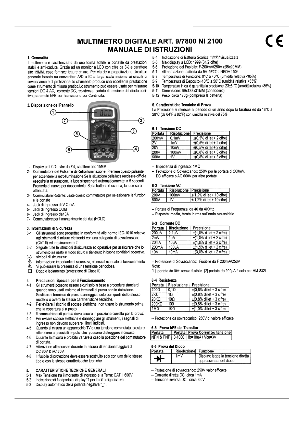
7. OPERATING INSTRUCTIONS
7-1 Attention before operation
7-1-1 Check 7V battery. If the battery voltage is less than 7V, display will
show “ ”, the battery should be replaced at this time to ensure measuring
precision.
7-1-2 Pay attention to the “ ” besides the input jack which shows that the
input voltage or current should be within the specified value.
7-1-3 The range switch should be positioned to desired range for
measurement before operation.
7-2 Measuring DC Voltage
7-2-1 Connect the black test lead to COM jack and the red to V mA jack.
7-2-2 Set the rotary switch at the desired Vrange position.
7-2-3 Connect test leads across the source or load under measurement.
7-2-4 You can get reading from LCD. The polarity of the red lead connection
will be indicated along with the voltage value.
NOTE:
1. When the value scale to be measured is unknown beforehand, set the
range selector at the highest position.
2. When only the figure’1’ or ‘-1’ is displayed, it indicates over-range
situation and the higher range has to be selected.
3. “” means you can’t input the voltage more than 600V, it’s possible
to show higher voltage, but it may destroy the inner circuit or pose a shock.
4. Be cautious against shock when measuring high Voltage.
7-3 Measuring AC Voltage
7-3-1 Connect the black test lead to COM jack and the red to V mA jack.
7-3-2 Set the rotary switch at the desired V~ range position.
7-3-3 Connect test leads across the source or load under measurement.
7-3-4 You can get reading from LCD.
NOTE:
1. When the value scale to be measured is unknown beforehand, set the
range selector at the highest position.
2. When only the figure’1’ or ‘-1’ is displayed, it indicates over-range
situation and the higher range has to be selected.
3. “” means you can’t input the voltage more than 600V, it’s possible
to show higher voltage, but it may destroy the inner circuit or pose a shock.
4. Be cautious against shock when measuring high Voltage.
7-4 Measuring DC Current
7-4-1 Connect the black test lead to COM jack and the red to the VmA
jack for a maximum 200mA current , for a maximum 10A current, move the
red lead to the 10A jack.
7-4-2 Set the rotary switch at the desired A range position.
7-4-3 Connect test leads in series with the load under measurement.
7-4-4 You can get reading from LCD. The polarity of the red lead connection
will be indicated along with the current value.
NOTE:
1. When the value scale to be measured is unknown beforehand, set the
range selector at the highest position.
2. When only the figure’1’ or ‘-1’ is displayed, it indicates over-range
situation and the higher range has to be selected.
3. “” means the socket mA’s maximum current is 200mA and 10A’s
maximum current is 10A, over current will destroy the fuse. Since 10A is
not fused, the measuring time should be less than 1 second to prevent
precision from affecting by circuit heating.
7-5 Measuring Resistance
7-5-1 Connect the black test lead to COM jack and the red to V mA jack.
7-5-2 Set the rotary switch at the desired Ωrange position.
7-5-3 Connect test leads across the resistance under measurement.
7-5-4 You can get reading from LCD.
NOTE:
1. When only the figure’1’ or ‘-1’ is displayed, it indicates over-range
situation and the higher range has to be selected.
2. For measuring resistance above 1MΩ, the mete may take a few
seconds to get stable reading.
3. When the input is not connected, i.e. at open circuit, the figure ‘1’ will
be displayed for the over-range condition.
4. When checking in-circuit resistance, be sure the circuit under test has
all power removed and that all capacitors have been discharged fully.
5. the value scale to be measured is unknown beforehand, set the range
selector at the highest position.
7-6 Transistor Testing
7-6-1 Set the rotary switch at ’hFE’ position.
7-6-2 Determine whether the transistor under testing is NPN or PNP and
locate the emitter, base and collector leads. Insert the leads into proper
holes of hFE socket on the front panel.
7-6-3 Read the approximate hFE value at the testing condition of base
current Ib10uA and Vce 3V.
7-7 Diode Testing
7-7-1 Connect the black test lead to COM jack and the red to VmA jack.
(the polarity of red lead is ‘+’)
7-7-2 Set the rotary switch at the F range position.
7-7-3 Connect the red lead to the anode and the black lead to the cathode of
the diode under testing.
7-7-4 You can get a reading from LCD.
NOTE:
1. The meter will show approximate forward voltage drop of the diode.
2. If the lead connections is reversed, only ‘1’ will be displayed.
7-8 Continuity Testing
7-8-1 Connect the black test lead to COM jack and the red to VΩmA jack.
7-8-2 Set the rotary switch at the range position.
7-8-3 Connect test leads across two points of the circuit under testing.
7-8-4 If continuity exists (i.e. resistance less than about 50 ), built-in
buzzer will sound.
NOTE:
If the input open circuit, the figure ‘1’ will be displayed.
8. Maintenance
8-1 Before attempting to remove the battery door or open the case, be sure
that test leads have been disconnected from measurement circuit top avoid
electric shock hazard.
8-2 To avoid electrical shock, remove test leads from measurement circuits
before replacing the fuse. For protection against fire, replace fuses only with
specified ratings: F-200mA/250V fuse.
8-3 Your must replace the test leads if the lead is exposed, and should adopt
the leads with the same specifications as origin.
8-4 Use only moist fabric or small amount of detergent but not chemical
solution for cleaning.
8-5 do not use the meter before the back cover is properly closed and screw
secured. Upon any abnormality, stop operation immediately and send the
meter for maintenance.
8-6 Please take out the battery when not using for a long time.
9. Accessories
[1] Test Leads: electric rating 1000V 10A
[2] Battery: 9V, 6F22 or NEDA 1604
[3] Fuse: F-200mA/250V
[4] Operator’s Manual
[5] Holster

This manual suits for next models

1

Other ELCART Multimeter manuals

ELCART 09/07850-00 NI2200 User manual

ELCART

ELCART 09/07850-00 NI2200 User manual

ELCART 9/9420 User manual

ELCART

ELCART 9/9420 User manual

ELCART 09/08260-00 NI 4600 Instructions for use

ELCART

ELCART 09/08260-00 NI 4600 Instructions for use

ELCART 09/07800-00 NI2100 User manual

ELCART

ELCART 09/07800-00 NI2100 User manual

ELCART Nimex NI-8002 User manual

ELCART

ELCART Nimex NI-8002 User manual

Popular Multimeter manuals by other brands

histest DT830 Series Owner's operation manual

histest

histest DT830 Series Owner's operation manual

Fluke 15B Calibration manual

Fluke

Fluke 15B Calibration manual

Keithley 2002 Calibration manual

Keithley

Keithley 2002 Calibration manual

East Tester ET1260 user manual

East Tester

East Tester ET1260 user manual

FLIR MR160 user manual

FLIR

FLIR MR160 user manual

Owon XDM2041 Series user manual

Owon

Owon XDM2041 Series user manual

Megger AVO410 user manual

Megger

Megger AVO410 user manual

Chauvin Arnox C.A 6165 quick start guide

Chauvin Arnox

Chauvin Arnox C.A 6165 quick start guide

Mastech MS8233A instruction manual

Mastech

Mastech MS8233A instruction manual

HP 3466A Operating and service guide

HP

HP 3466A Operating and service guide

Kaise SK-7820 instruction manual

Kaise

Kaise SK-7820 instruction manual

Mastech M266 Series Operator's instruction manual

Mastech

Mastech M266 Series Operator's instruction manual

HP 3478A operating instructions

HP

HP 3478A operating instructions

Sperry instruments SMART meter operating instructions

Sperry instruments

Sperry instruments SMART meter operating instructions

Pyle PDMT08 manual

Pyle

Pyle PDMT08 manual

Hanna Instruments HI 9829 instruction manual

Hanna Instruments

Hanna Instruments HI 9829 instruction manual

Klein Tools CL100 instruction manual

Klein Tools

Klein Tools CL100 instruction manual

Omega HHM9007R user manual

Omega

Omega HHM9007R user manual

manuals.online logo
manuals.online logoBrands
  • About & Mission
  • Contact us
  • Privacy Policy
  • Terms and Conditions

Copyright 2025 Manuals.Online. All Rights Reserved.