99
K K
1.
2.
3.
4.
5.
6.
8.
9.
10.
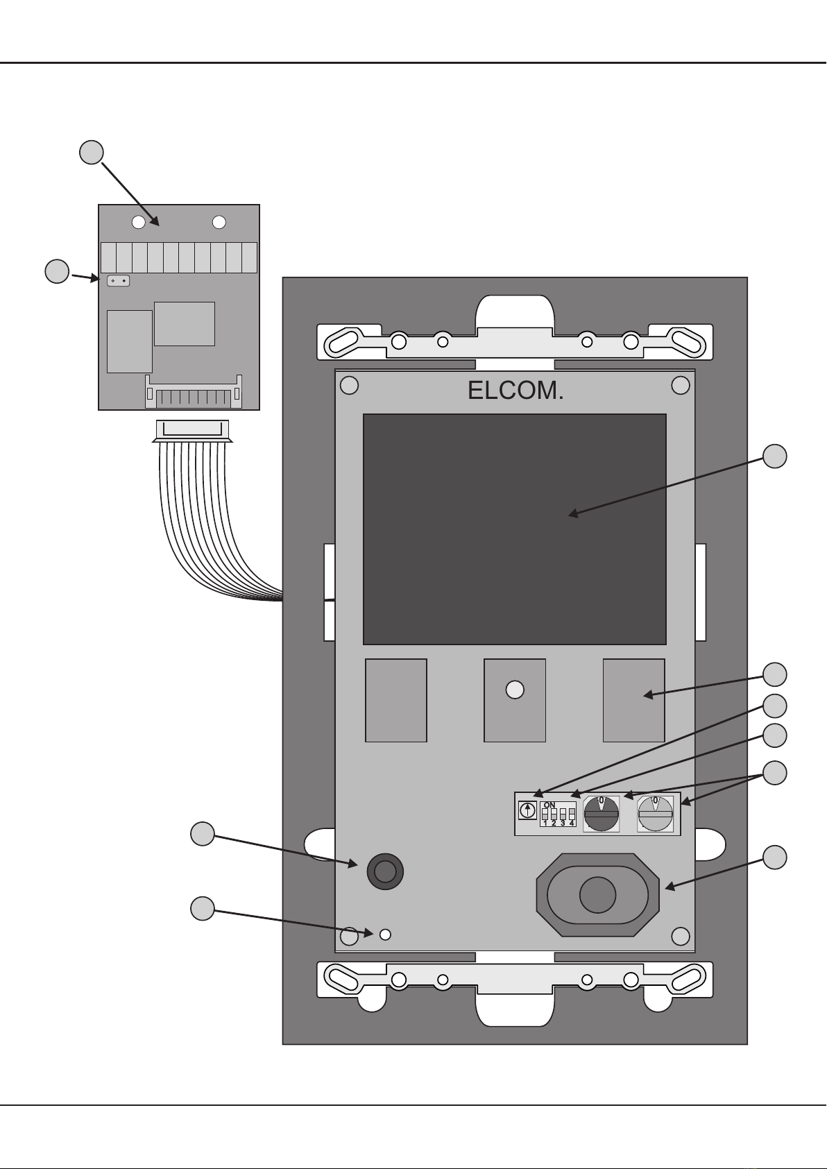
Terminal blocks
ELCOM i2 bus terminal (both "a" terminals are connected internally)
Connection for storey call button (counterpole terminal a or b)
NO (Normal Open) relay contact, 24V/1A (see Programming for functions)
Video power supply (15VDC / 300mA)
Video input (symmetrical 1Vp-p Z=100Ohm)
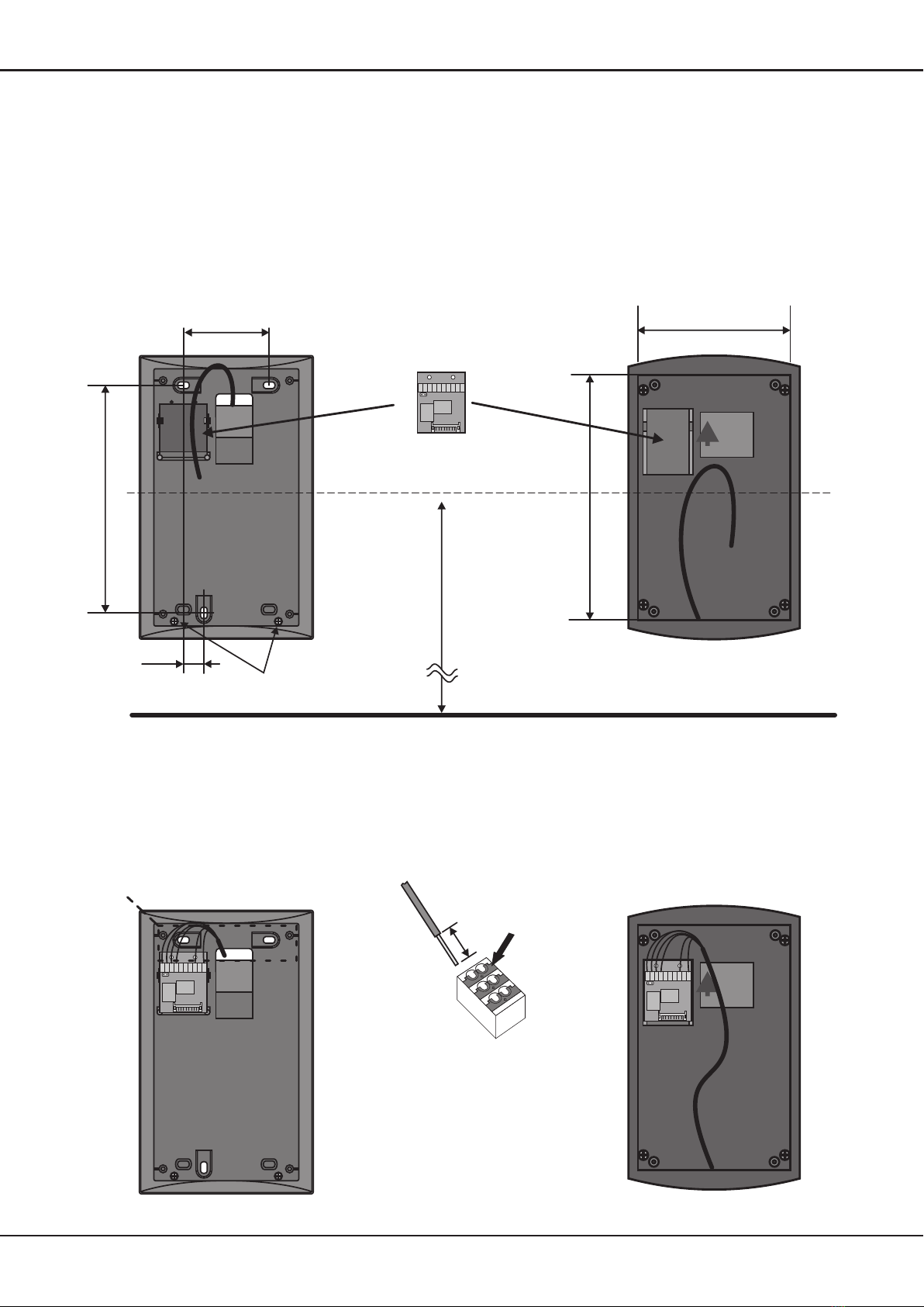
Video terminator
The jumper must be plugged into the last telephone on the video line,
but pulled out for all the previous telephones! Each video line must be
completed at the end. Video strand termination per line: 100 ohms. Be sure the
Installation instructions noted in our system manual.
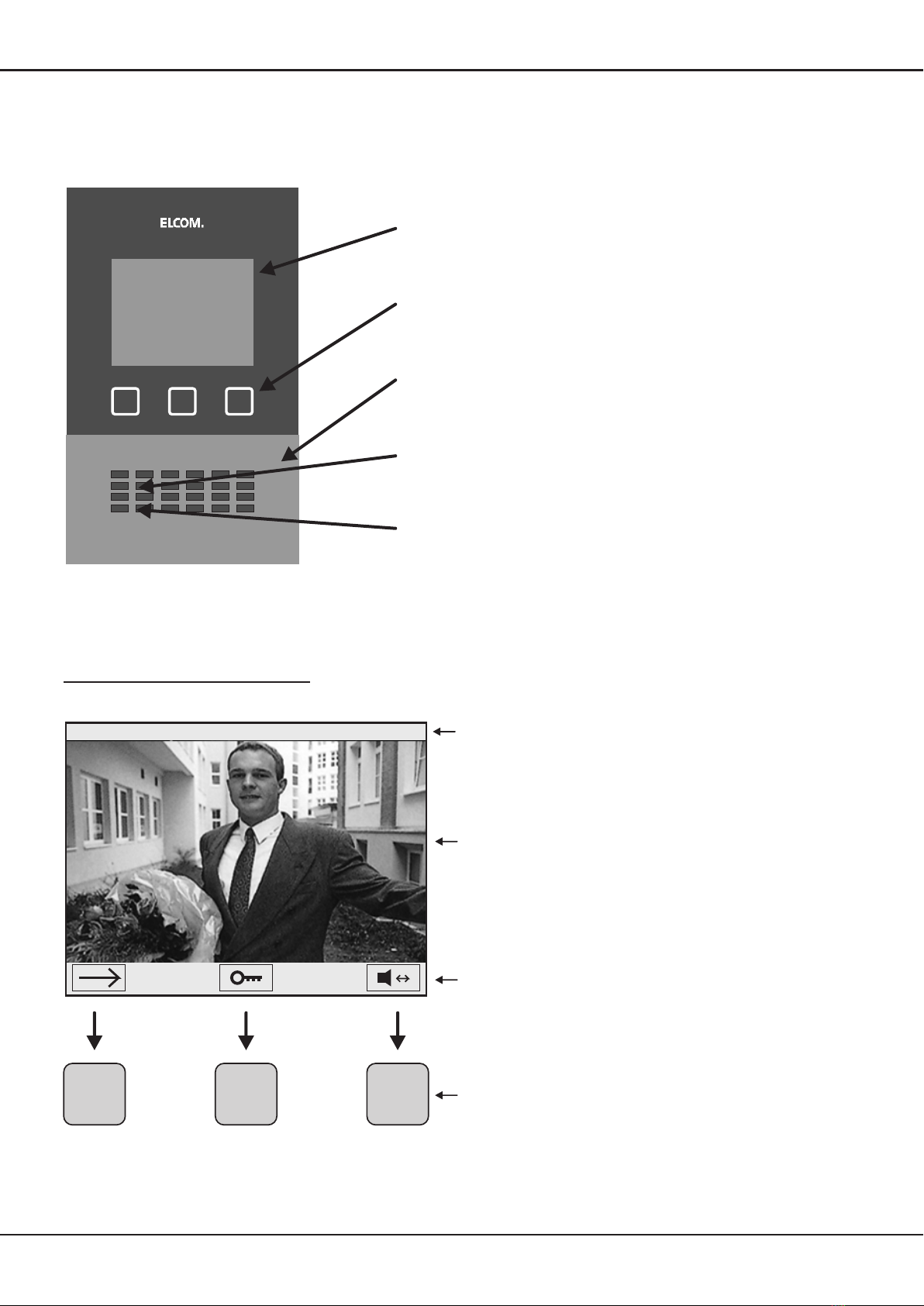
4" TFT-Display
Sensor buttons
Video image quality potentiometer
The adjustment control can be used to compensate partly for line losses.
Operating mode switches
Address dial
black: Group address (0-F)
Telephone address (0-F)
At most 3 telephones may be installed with the same address!
Speaker
Microphone
Status LED
7.
blue:
aab
R
+ -
V W
1
2
3
4
OFF
OFF
OFF
OFF
ON
ON
ON
ON
Switch Function
Manual door and camera actuation locked
Storey call forwarding to parallel addressed telephone
Setup menu locked
Parallel call to telephone address 0 for identical group address
Manual door and camera actuation possible (factory setting)
No storey call forwarding (factory setting)
Changes to Setup menu possible (factory setting)
Normal mode (factory setting)