SENSIT Technologies RAMP Quick guide

REMOTE AFFORDABLE MULTI-POLLUTANT SENSOR
SENSIT® RAMP
SENSOR OPERATION
AND CONFIGURATION GUIDE
READ AND UNDERSTAND INSTRUCTIONS BEFORE USE
851 Transport Drive
Valparaiso, IN 46383-8432
Phone: 888 473 6748
219 465 2700
Fax: 219 465 2701
Email: info@gasleaksensors.com
Web: www.gasleaksensors.com

RAMPSensorOverview
SensorSpecifications
General
Overview Parameter
Weight Baseunit:7.5lbs
Dimensions Fullyassembledwithoutanemometerorantenna1
DxWxH(5”x10”x12”)
Mounting Attachedmountingflanges
VoltageRequirements 18V–24VDCCharging(wiredadapterorsolarpanel)
CurrentRequirements 2Amaxcurrentdrawwhencharging
OperatingRuntime 3‐15daysbatterybackup2
OperatingTemp ‐20°Cto50°C
DataOutputs Digitalwiredoutput(3.3VTTL‐USB)
Wireless(3GCellularIncluded)3
Optionalanalyticsonserver4
SDcarddatabackup5

Notes:
1. Theanemometeristobemountedseparatetoapole.Couldbesamepole
assensor.
2. Batterybackuptimedependsonrunmodeandfrequencyoftransmission.
3. RequiresSIMcardandsuitabledataplanonAT&TorT‐mobile
4. Cloudbasedanalyticscanbedevelopedwithadditionalcontract
5. WhenremovingSDcardtoobtaindata,itisrecommendedtopoweroffthe
sensorboxpriortoreinsertingtheSDcardtoavoidpossibleerrors.Ifthe
systemstopsrespondingafterinsertinganSDcard,powerdownthesensor
andturnbackon.

Sensors
Overview Parameter
CODetectionRange 100ppb–25ppm
COAccuracy +/‐100ppbminor20%
NODetectionRange20ppb–25ppm
NOAccuracy+/‐20ppbminor20%
NO2DetectionRange20ppb–25ppm
NO2Accuracy+/‐20ppbminor20%
O3DetectionRange20ppb–25ppm
O3Accuracy+/‐40ppbminor50%
CO,NO,NO2,O3ResponseTimes 60‐90seconds1
CO,NO,NO2,O3DetectionMethod Electrochemical
CO2DetectionThreshold100‐2000ppm2
CO2Accuracy +/‐200ppmminor20%
CO2ResponseTime 15‐30seconds
CO2DetectionMethod NDIROptical
PM2.5DetectionThreshold 1‐1000g/m3
PM2.5Accuracy +/‐10g/m3minor50%
PM2.5ResponseTime 15‐30seconds
PM2.5DetectionMethod LaserScattering
PeriodicMaintenance Periodiccleaningofsensoropeningsof
dust,zeropointcalibration,andsingle
pointcalibration.Userreplacementof
sensorsiseasilyperformedasneeded.
AdditionalIncludedSensors Additionalsensorscanbeadded(external
ports)3

Notes:
1. Iftheunithasbeenoffforanextendedperiodoftime,itwilltake
approximately12‐24hoursfortheelectrochemicalsensorstostabilize
completely.
2. ThereareadditionalCO2sensorsavailablewithidenticalformfactorsif
higherconcentrations(e.g.10,000ppm)aredeterminedtobenecessary.
3. TheanemometerthatisdesignedtoworkwiththeRAMPistheDavis
VantagePro2Anemometer
(https://www.davisinstruments.com/product/anemometer‐for‐vantage‐
pro2‐vantage‐pro/)

SensorExteriorFeatures(FrontExterior)
FrontView
Antenna
L
e
f
t
S
i
de
Ri
g
htSide
BottomSide
To
p
Side
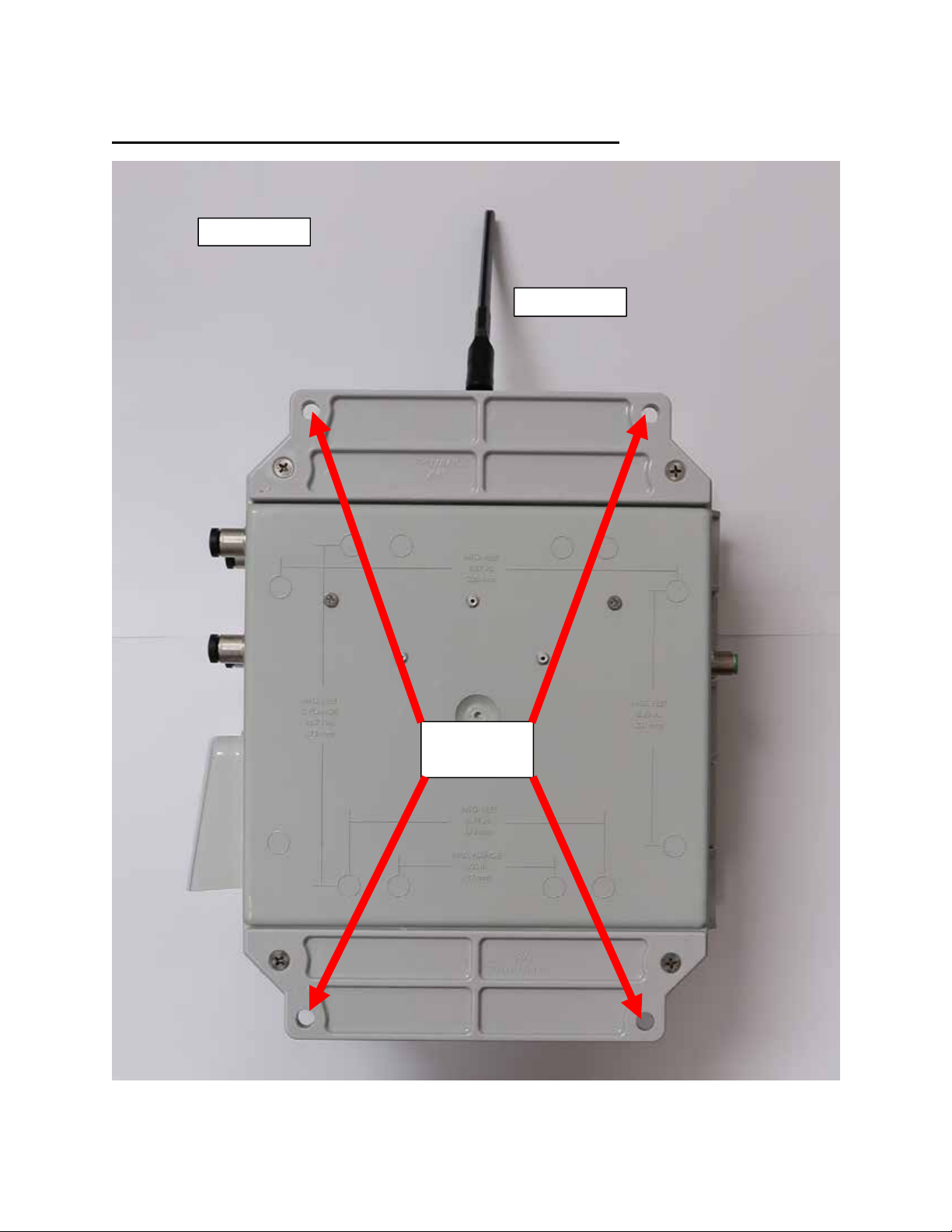
SensorExteriorFeaturesBackSideExterior)
BackView
Antenna
Mounting
Holes

SensorExteriorFeatures(LeftSideExterior)
LeftView
PowerSwitch
USB/Power
Port
Antenna

SensorExteriorFeatures(RightSideExterior)
Ri
g
htView Auxiliar
y
DevicePorts
Port1
(Anemometer)
Antenna
VentForPM2.5Sensor
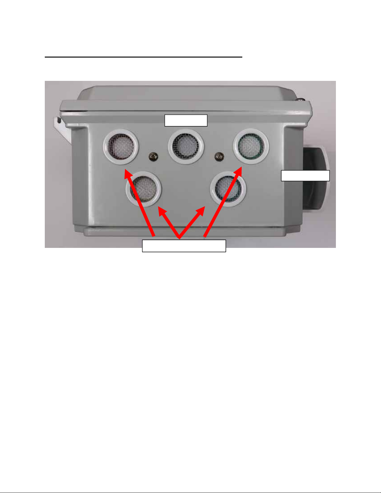
SensorExteriorFeatures(BottomExterior)
Note:Donotobstructsensoropenings.Usermustinstallsensorenclosurewith
sensoropeningsfacingdownwardtoavoidwateranddebrisaccumulation.
ElectrochemicalSensors
CO2Sensor
PM2.
5
Se
n
so
r

SensorFeatures(FrontInterior)
SD
Cell
(SIM)

QuickStartDeploymentGuide
ItisrecommendtouseacomputerandthesuppliedUSBcablewhensettingup
thesensorunittoverifytheoperationofthesensors,systemoutput,andcellular
dataconnectivity(ifapplicable).
1) Unpackthesensorunitandcheckforanyphysicaldamageorobstructions
atthesensoropenings.Openenclosurecoverandcheckforanylooseor
damagedcomponents.Makesureallwiresaresecurelyfastened.
2) HookupUSBcablesensorandinitializeterminalconnection.Poweronunit
andverifythattheSDcardwasdetectedandinitialized.
3) EnterintoUSBmodefromstartuporfromconfigurationmenu.Verifythe
sensoroutputsarereasonableortrendingtowardreasonablevalues
keepinginmindthestabilizationtimefortheelectrochemicalsensors.The
outputformatisshownbelow:
Heading
Description
Units/Format
DAT
E
LocalDateandTime MM/DD/YYHH:MM:SS(24H)
CO
CO PPB
NO/SO2
1
NO/SO2 PPB
NO2
NO2 PPB
O3
O3 PPB
CO2
CO2 PPM
T
Temperature °C
RH
RelativeHumidity %
PM1
PM1.0 g/m3
PM2.5
PM2.5 g/m3
PM10
PM10 g/m3

Port
1
2
ExternalModule Appearsonlyifattached
Port
2
2
ExternalModule Appearsonlyifattached
Port
3
2
ExternalModule Appearsonlyifattached
Port
4
2
ExternalModule Appearsonlyifattached
WD
WindDir DegreesfromNorth
WS
WindSpeed Mph
BATT
BatteryVoltage Volts(4.2‐3.4V)
CHRG
ChargingCurrent mA
RUN
RunCurrent mA
SD
SDStatus (1–OK
,
0–refertoSTA
T
)
RAW
Rawsensorsignals CO,NO/SO2
,
NO2
,
O3
STAT
SystemInformation *SeeBelow*
4) Theheading‘STAT’containsdiagnosticinformationdetailedbelow:
STAT=HEX1,HEX2,HEX3,(EXTENDEDINFO)
HEX1
Bit
Description
0
SDInitStatus(0
–
InitFailure,1
–
InitSuccess)
1
SDCardPresence(0
–
NotInstalled,1
–
Installed)
2
SDWriteStatus(0
–
NoError,1
–
WriteError)
3
TempFlag(1
–
Normal,0
–
LowTemp)
4
ChargeStatus(0
–
ChargeOn,1
–
ChargeOff)
5
CO2ConnectionStatus(0
–
NotInstalled,1
–
Installed)
6
PTR1ConnectionStatus(0
–
NotInstalled,1
–
Installed)
7
AlwaysZero
HEX2
Bit
Description
0
COReadError(0
–
OK,1
–
Error)
1
NO/SO2ReadError(0
–
OK,1
–
Error)
2
NO2ReadError(0
–
OK,1
–
Error)
3
O3ReadError(0
–
OK,1
–
Error)
4
Port1ConnectionStatus(0
–
NotInstalled,1
–
Installed)

5
Port2ConnectionStatus(0
–
NotInstalled,1
–
Installed)
6
Port3ConnectionStatus(0
–
NotInstalled,1
–
Installed)
7
Port4ConnectionStatus(0
–
NotInstalled,1
–
Installed)
H
E
X3
Bit
Description
0
Port1PowerStatus(0
–
PowerOff,1
–
PowerOn)
1
Port2PowerStatus(0
–
PowerOff,1
–
PowerOn)
2
Port3PowerStatus(0
–
PowerOff,1
–
PowerOn)
3
Port4PowerStatus(0
–
PowerOff,1
–
PowerOn)
4
Port1FaultStatus(0
–
NoFault,1
–
Fault)
5
Port2FaultStatus(0
–
NoFault,1
–
Fault)
6
Port3FaultStatus(0
–
NoFault,1
–
Fault)
7
Port4FaultStatus(0
–
NoFault,1
–
Fault)
5) Ifoperatingwithaweatherstation,orienttheweathersensorsuchthatitis
pointingNorth.Failuretodothiswillresultinarbitrarywinddirection.
6) AfterverifyingfunctionalityremovetheUSBcable.Ifplanningtorunin
USBmode,installapoweradapterorasolarpanelforlongterm
deploymentapplications.Otherwise,powercycletheRAMP,theninstalla
poweradapterorasolarpanelforlongtermdeploymentapplications.
Notes:
1. Position2isdesignatedforeitheranNOorSO2electrochemicalsensor
2. TheHeadingfortheportswillbespecifictothedevicethatisconnected
not‘Port#’

USBCommunication&ConfigurationMode(Sensor)
TheRAMPsensorsallowforthereconfigurationofseveralparameterspertaining
totheoperationofsystem.Adjustmentoftheseparametersisonlyaccessiblefor
ashortperiodoftimeafterpoweringonthesensor(~10s).Theseparametersare
storedinnon‐volatilememoryandareretainedduringsubsequentpowercycling.
Documentationoftheseparametersislistedbelow.
RequiredComponents:
‐ Sensor
‐ USBdatacable
‐ Computerwithaserialportterminalsoftwareprogram(e.g.CoolTerm)
SensorQuickstartInstructions
1) ConnecttheUSBcabletotheRAMPandcomputerandestablishthe
communicationlinkintheterminalsoftware.
2) Turnonpowerswitchandobserveinitializationprocess.Afterinitializingthe
microcontrollerandprintingRAMPinformation,thesystemwillsystemwill
prompttheuserto:
“EnterConfigurationMode?(YES)”
or
“EnterCalibration(USB)Mode?(CAL)”
3) Configurationmodeallowsaccesstoconfigurationsettingsandsystem
settings.ToenterconfigurationmodetypeYesatthepromptandhitenter.
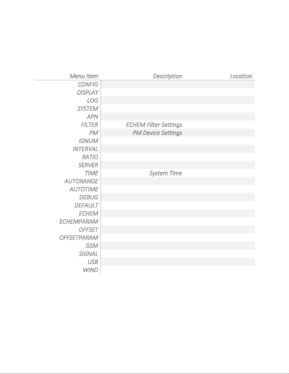
Themenusarealltext‐basedandeasytofollow.Thefollowinglistcontainsall
theadjustablewithinthemenu:
Menu
Item
Description
Location
CONFIG
Common
settings
Root
Menu
DISPLAY
Prints
device
settings
Root
Menu
LOG
A
llows
user
to
save
message
Root
Menu
SYSTEM
System
settings
Root
Menu
A
PN
Cellular
Data
APN
Config
Menu
FILTER
ECHEM
Filter
Settings
Config
Menu
PM
PM
Device
Settings
Config
Menu
IDNUM
Device
ID
Numbe
r
Config
Menu
INTERVAL
Output
Interval
Config
Menu
RATIO
Points
Between
Cell
Post
Config
Menu
SERVER
Server
Address
for
Cell
Config
Menu
TIME
System
Time
Config
Menu
A
UTORANGE
A
utomatic
ADC
Selection
System
Menu
A
UTOTIME
A
utomatic
Cell
Time
Sync
System
Menu
DEBUG
Enable
verbose
USB
Output
System
Menu
DEFAULT
Reset
all
settings
System
Menu
ECHEM
Sensor
Parameters
System
Menu
ECHEMPARAM
Display
echem
parameters
System
Menu
OFFSET
Offset
and
slope
settings
System
Menu
OFFSETPARAM
Display
offset/slope
System
Menu
GSM
GSM
Test
and
Info
System
Menu
SIGNAL
Cell
signal
acquire
and
test
System
Menu
USB
Toggle
remote/local
mode
System
Menu
WIND
Wind
sensor
settings
System
Menu
Note:WiththeexceptionofDEBUGoption,allchangesmadewithinmenuare
storedinNVRAMandwillberetainedonpowercycling
4) Calibrationmodeallowstheusertoobserveacontinuoussensoroutputas
wellascalibratethezeroandslopeofthefollowingsensors:CO,NO,NO2,O3,

CO2,PM2.5reading.Calibrationmodeistemporaryandwillbelostupona
systempowercycle.ToentercalibrationmodetypeCalattheprompt.
‐ Tosetnewzerolevelexposethesensortozeroairandtypethefollowing:
CO:zero,NO:zero,NO2:zero,O3:zero,CO2:zero,orPM25:zero
‐ Tocalibratethesensortoaknownleveloftargetgasreplace‘zero’withthe
actualppbreadingforCO,theactualppmreadingforCO2,ortheg/m3
readingforPM2.5
(e.g.CO:10000wouldcalibrateto10000ppbCO,CO2:1500would
calibrate1500ppmCO2,orPM25:20wouldcalibrate20g/m3)
Note:Pleaseallow1‐2outputsforthesensorreadingtoupdate.

HardwareandSoftwareInstallationGuide
1) DownloaddriversforFTDISerialAdapterandinstalldrivers
http://www.ftdichip.com/Drivers/VCP.htm
2) Openserialterminalprogramofyourchoice.CoolTermisrecommendedand
instructionsforusingCoolTermarefoundbelow.CoolTermisavailablefor
Windows,Mac,andLinux.CoolTermcanbedownloadedforfreefromhere:
http://freeware.the‐meiers.org/
1) Extract‘Software_CoolTerm’tothedirectoryofyourchoosing.Toavoid
certainpermissionsissuesdonotextractinto“ProgramFiles”.Itis
recommendedtoextracttothedesktopifpossible.
2) Openthe‘CoolTerm’application.Youmayreceiveanerrorindicatingthat
noserialportsarefounddependingonwhatishookeduptothecomputer.
Clickokaytocontinue.

3) Click‘Options’asshownbelow
a. ‘SerialPort’optionsshouldopenbydefault.Ifnot,selectSerialPort
optionsfromthelistofavailableoptionsasshownbelow.Alldefault
optionsshouldbecorrectbutpleaseverify.Clickon‘Port’dropdown
listandmakenoteofanyavailableports.PlugintheUSBcableand
waitforhardwareinstallationtofinish.Click“Re‐ScanSerialPorts”.
ThenewlyaddedportistheUSBcable.Selectthisport.

b. Select‘Terminal’optionsfromlistofavailableoptionsandselect
‘LineMode’asshownbelow.Linemodeaddsatextentrybaratthe
bottomofthescreenthatisusefulforsendingcommandstothe
connectedsensor.
Table of contents
Other SENSIT Technologies Accessories manuals

Popular Accessories manuals by other brands


Baby Jogger
Baby Jogger CITY MINI 2 Instructions for use

Ono Sokki
Ono Sokki GS-1713A instruction manual

wattstopper
wattstopper PW-100 installation instructions

GOAL ZERO
GOAL ZERO YETI 500X LITHIUM user guide

Silvercrest
Silvercrest HG01100-BS Operation and safety notes

TERRA NOVA
TERRA NOVA Wild Country Zonda Driveaway Awning instructions


