Elcon SA5A User manual
2018-04-20
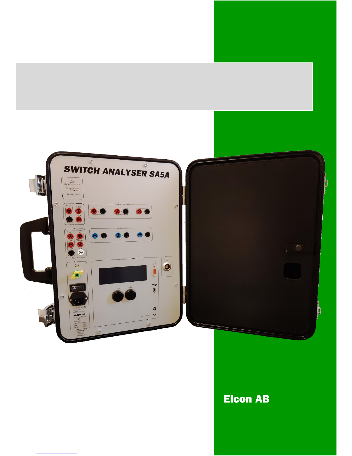
SWITCH ANALYSER SA5A
USER MANUAL

Page 2 (24)
Rev 0 2018-04-20 www.elcon.se
Go to INDEX.
INDEX
INDEX ........................................................................................................................................................................................2
1. GENERAL DESCRIPTION.........................................................................................................................................................3
2. SAFETY REGULATIONS ..........................................................................................................................................................4
2.1. General safety regulations ............................................................................................................................................4
2.2 Power supply and protective grounding ........................................................................................................................5
3. Connections ..........................................................................................................................................................................5
3.1 Connections for time measurement ..............................................................................................................................5
3.1.1 Safety regulations ...................................................................................................................................................5
3.1.2 Principals for connections to SA5A .........................................................................................................................5
3.1.3 Connections for one breaking unit per phase.........................................................................................................6
3.1.4 Connections for two or more breaking units per phase .........................................................................................6
3.2 Connection of the breaker operating mechanism .........................................................................................................7
3.2.1 Safety regulations ...................................................................................................................................................7
3.2.2 Connection of operating coils .................................................................................................................................7
3.2.3 Connection of motor...............................................................................................................................................7
3.3 Connection of transducers .............................................................................................................................................8
3.4 Connection of a PC .........................................................................................................................................................8
4. OPERATING INSTRUCTION FOR USING SA5A STAND ALONE................................................................................................9
4.1 Before operation ............................................................................................................................................................9
4.2 Standalone operation of SA5A .......................................................................................................................................9
5 Technical Specification. .......................................................................................................................................................10
6.0 MAINTENANCE..................................................................................................................................................................13
6.1 Before use. ...................................................................................................................................................................13
6.2 After use. ......................................................................................................................................................................13
6.3 Storing the SA5A...........................................................................................................................................................13
6.4 Every year or when necessary......................................................................................................................................13
6.7 Upgrading SA5A internal software. ..............................................................................................................................13
6.8 SA5A PROGRAM LOADER in display. ............................................................................................................................14
7.0 ADJUSTMENTS ..................................................................................................................................................................16
7.1 Instrument needed.......................................................................................................................................................16
7.2 General .........................................................................................................................................................................16
7.3 General calibration procedure .....................................................................................................................................17
7.3.1 Calibration wizard for Voltage measurement on analogue inputs: ......................................................................18
7.3.2 Calibration wizard for Current measurement on analogue inputs: ......................................................................20
7.3.3 Calibration wizard of analogue transducer input: ................................................................................................22
8 Transportation/SCRAPPING/Recycling. ...............................................................................................................................24
9 SA5A Accessories. ................................................................................................................................................................24

Page 3 (24)
Rev 0 2018-04-20 www.elcon.se
Go to INDEX.
1. GENERAL DESCRIPTION
The is a portable instrument, especially designed to analyze Circuit Breakers in the field.
Even though is intended for use together with a computer, it can be used stand-alone for some simpler
measurements. To be handy in field works, the is built into a small and robust metal carry case. On the cover
section of the carry case, a notebook computer can be placed while testing.
The measurements that can be made without a Windows computer are: voltage and current for both motor and coils,
time for three independent contacts in, open, close and close-open operations and static resistance of main contacts.
Contact time measurements.
There are three main and three auxiliary contact indication inputs. Main contact max output 30 mA during operations and
can also indicate pre-insertion resistors simultaneously. Auxiliary contact inputs can handle both free and live contacts. All
contact inputs are of type semi protected banana-jacks and are protected against faulty connections and high voltage
discharges.
Travel transducer.
One, digital or analogue, travel transducer, can be used for measurement.
Operating coil control.
With an external power supply connected through this section the operating coils can be fully controlled. The current flow
through the coils and the supply voltage are measured.
Motor monitoring.
In the Auxiliary section there is provisions to monitor current and voltage from an external motor supply.
Internal sampling.
Sampling frequency for analogue and digital functions can be programmed for frequencies up to 50 kHz. Note! The PC-
software sets the sampling frequency.
Power supply
The SA5A must powered with an external AC- or DC- power supply.
Environmental
SA5A is built in a small metal carry case designed for rough handling in tough outdoor environments. All connections are
protected for any possible type of electrical discharges and disturbances. Some of the inputs are even protected against
faulty connections up to 300V peak.
PC-Computer
In most cases a standard windows notebook computer can be used but for tougher environments an outdoor type is
recommended. For recommended minimum requirements for the notebook computer. See BTS11 User manual
PC-software
See separate manual BTS11 User manual for more information.

Page 4 (24)
Rev 0 2018-04-20 www.elcon.se
Go to INDEX.
2. SAFETY REGULATIONS
Important!
This instrument shall only be used by authorized and educated personnel.
It is the operator’s responsibility to read and follow all operating and safety instructions for connecting and using this
instrument.
Always keep the below safety instructions in mind when using the instrument.
2.1. GENERAL SAFETY REGULATIONS
•Local safety regulations.
Always follow local safety regulations for work on high-voltage circuit breakers.
•Ground connection.
Always connect the separate ground terminal (green/yellow) on SA5A to protective ground before any other
connections.
The SA5A unit can only be used in electrical system with a single ground.
If there is a High voltage ground and Low voltage ground make sure that there is no potential voltages
difference between these grounds. If a voltages difference exists between grounds, consult local safety
regulations.
Check that the separate protective ground wire is in good condition before connection.
Make sure that the power socket for mains is a grounded outlet and that the power cable is in good
condition before connected the main power to the control unit SA5A.
•Connections.
Before connecting the SA5A to a high-voltage circuit breaker, make sure that the breaker poles are in
position CLOSE, and disconnected from the power line at both sides. The breaker must also be grounded on
at least one side.
Follow local safety regulations for work on high-voltage circuit breakers.
To avoid unintentional breaker operation!
Never do any work on a circuit breaker unless the control circuits of the breaker are disconnected from the
SA5A control outputs or from any other remote control device.
All cables shall first be connected to the SA5A before any connections to the test object.
Use of touch-protected connectors is required for personal safety.
Only use original cables for connection and make sure that the cables are in good conditions.
When the SA5A is connected to a wall socket, the socket must be a grounded power outlet.
Note! The inputs for coils “Uc” and motor “Um” are not fused!
Make sure that the output powers to these inputs are fused with maximum 32A.
Take care when working near bare connectors and bus bars. Contact with a conductor may cause an
electrical shock. Take special care at wet conditions.
Page 5 (24)
Rev 0 2018-04-20 www.elcon.se
Go to INDEX.
•Testing the circuit breaker
Make sure that surrounding personal can’t touch the breaker during an operation.
If a test sequence shall be running in automatic mode it’s absolutely necessary to have a security circuit that
prevent surrounding personal to touch the test object during the sequence.
The power supplies for coils and motor must be interlocked to a security circuit that cut the power if the
security circuit is open.
2.2 POWER SUPPLY AND PROTECTIVE GROUNDIN G
The SA5A can be powered from any AC or DC source, 100-250 V.
When the SA5A is connected to a wall socket, the socket must be a grounded power outlet.
IMPORTANT!
The SA5A have a separate grounding terminal (green/yellow) that must be grounded to the nearest protective earth
(ground) with a separate wire.
3. CONNECTIONS
3.1 CONNECTIONS FOR TIME MEAS UREMENT
3.1.1 SAFETY REGULATIONS
Important!
When only one side of the breaker is connected to earth (ground), special precautions must be observed. To protect
service personnel and the measuring equipment from surges, two important rules must be followed closely.
•The SA5A case must be earthed (grounded).
•All circuit breaker connections and disconnection’s must be made while the breaker poles are closed and
connected to earth (ground) on least one side.
•To avoid unintentional breaker operation! Never do any work on a circuit breaker unless the control circuits of
the breaker are disconnected from the SA5A control outputs.
•Use of touch-protected connectors.
3.1.2 PRINCIPALS FOR CONNECTIONS TO SA5A
To get a useful protocol and to fit to the PC-software it is necessary to connect contacts in a certain way:
•Use contacts "A" - "C" for main contacts.

Page 6 (24)
Rev 0 2018-04-20 www.elcon.se
Go to INDEX.
•Use contacts "a" - "c" for connection of auxiliary contacts (live or free)
Note!
Do not exceed the input voltage limit of 250 V AC or 400 V DC.
3.1.3 CONNECTIONS FOR ONE BREAKING UNIT PER PHASE
Figure 2.1 Connections for a one breaking unit per phase
3.1.4 CONNECTIONS FOR TWO OR MORE BREAKING UNITS PER PHASE
Note! Only one phase with 2 breaking elements is shown
Figure 2.2 Connections for two breaking units per phase

Page 7 (24)
Rev 0 2018-04-20 www.elcon.se
Go to INDEX.
3.2 CONNECTION OF THE BREAKER OPERATING MECHANISM
3.2.1 SAFETY REGULATIONS
Important!
•The SA5A case must be grounded.
•Warning! Do not short-circuit or touch the auxiliary voltage.
Use of touch-protected connectors is required for personal safety.
•The inputs for coils “Uc” and motor “Um” are not fused!
Make sure that the powers to these inputs are pre-fused with maximum 32A.
•Never do any work on a circuit breaker unless the control circuits of the breaker are disconnected from the SA5A
control outputs. (avoiding unintentional breaker operations)
Note!
The white 4 mm panel socket "ISOL" is an isolated connection that can be used to disconnect the control circuits of the
breaker.
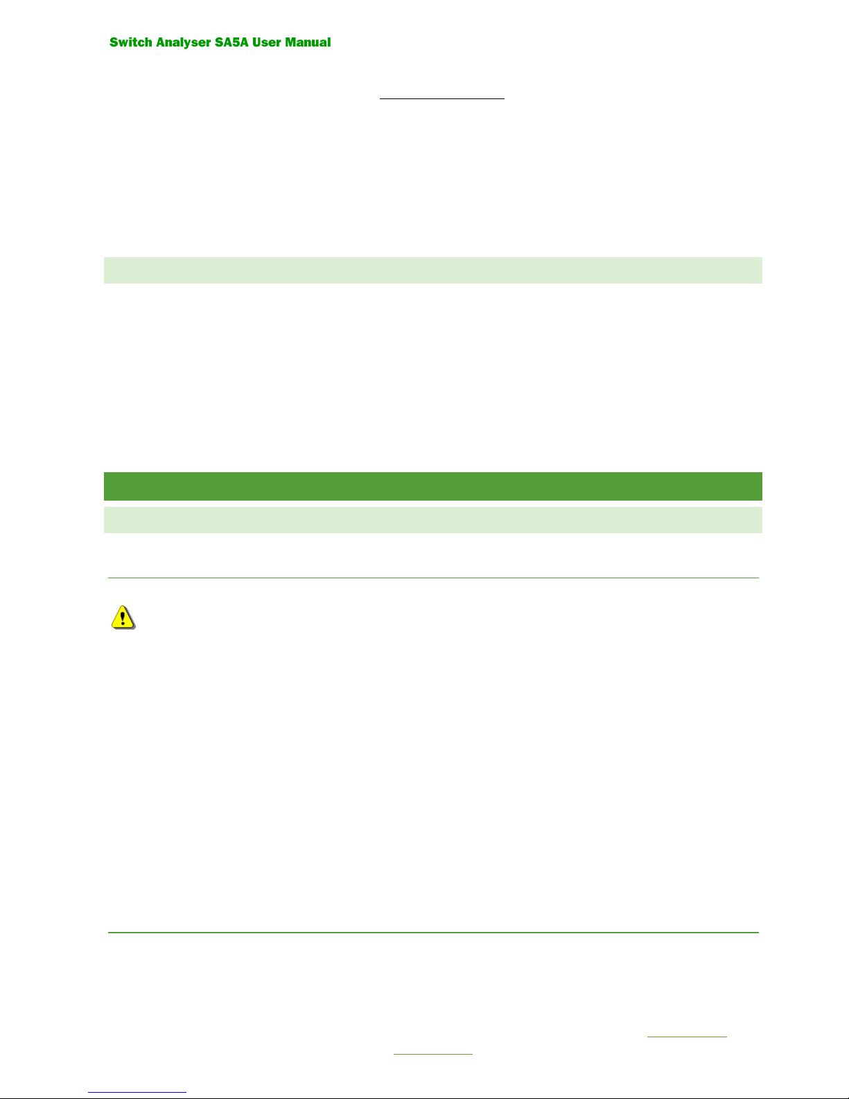
3.2.2 CONNECTION OF OPERATING COILS
See figure 2.6
•Connect the coil voltage to the inputs "Uc" and "COM".
Connection to COM is optional and is only used for monitoring the voltage.
•Connect the positive connection of the closing coil and the positive connection of the opening coil to the outputs
CLOSE and OPEN.
•Connect the negative connections of the operating coils to the negative connection of the coil voltage.
3.2.3 CONNECTION OF MOTOR
See figure 2.6
•Connect the auxiliary voltage to the inputs "Um" and "COM"
•Connect the motor connections to the output "MOTOR" and to the negative connection of the auxiliary voltage.
Note!
The connection of the motor circuit is optional and is only necessary for monitoring the voltage and current
Page 8 (24)
Rev 0 2018-04-20 www.elcon.se
Go to INDEX.
+
~
-
~
+
~
-
~
Coil
Voltage
Motor
Voltage
Motor
Close Coil
Open Coil
Coil interlocking
Figure 2.6 Connection of the breaker operating mechanism
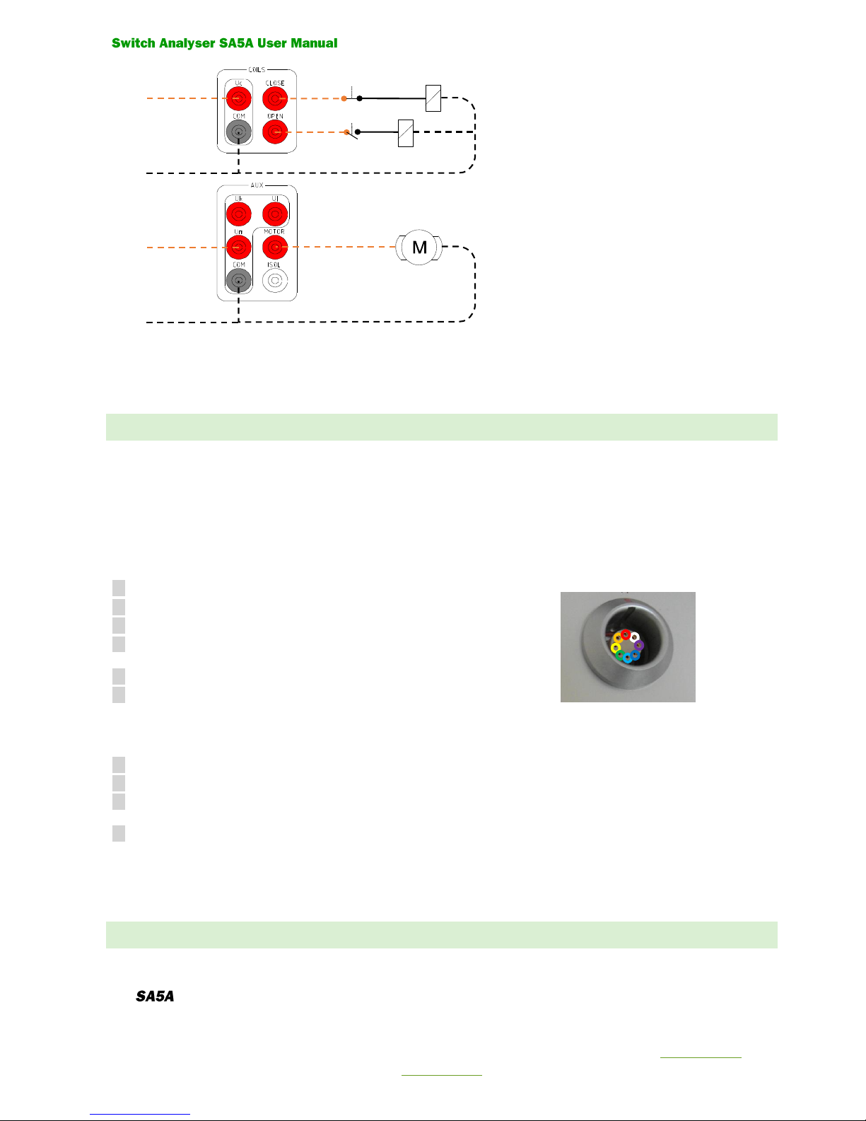
3.3 CONNECTION OF TRANSDUCERS
One pulse- or analog transducers can be connected to the input "T1".
The connection must be done with a special cable connector:
Connector: LEMO FGG.2K.308.CLCK90
Pin Description for a digital pulse transducer.
1 Pulse 1.
2 Pulse 1 inverted.
3 Pulse 2.
4 Pulse 2 inverted
5 +5 VDC
6 Ground.
Pin Description for an analog transducer
5 +5 VDC
6 Ground
7 Analogue measurement (Wipe)
8 Is not used.
Tip!
Use prefabricated cables for connection.
3.4 CONNECTION OF A PC
Any standard Windows PC with one free RS232, USB 2.0, USB 3.0 port can be connected.
The can be connected with 3 different methods.

Page 9 (24)
Rev 0 2018-04-20 www.elcon.se
Go to INDEX.
•USB Mini to USB cable. (Max 1 meters)
•RS232 9 Pol Male to 9 Pol Female cable. (Max 2 Meters)
If computer is not equipped with RS232 port an USB to RS232 adapter can be used.
•Bluetooth communication kit
Use a standard straight serial RS232 PC-cable with a 9 pole DSUB Male Female connectors, for connection to .
4. OPERATING INSTRUCTION FOR USING SA5A STAND ALONE
The instruction below only handles the operating instruction for using the SA5A as a stand-alone instrument.
See separate BTS11 User manual for use of the PC-software
4.1 BEFORE OPERATION
Important!
Read chapter 2. SAFETY REGULATIONS before any connections.
4.2 STANDALONE OPERATION OF SA5A
The SA5A LCD-display and two operation buttons "OPEN" and "CLOSE" for simpler operations and measurements.
Starting up the display will present the version of the internal software.
After unit is started the display shows, the next operation that can
be done: Ready for Open or Ready for Close"
Voltage value for inputs: Uc, Uk, Ul, Um.
Current value: Im for motor.
Symbol
Voltage type
V=
Volt DC
V~
Volt AC
A=
Ampere DC
A~
Ampere AC
When the display shows
Pressing Button
OPEN: A open operation is done
CLOSE: A close operation is done
CLOSE and OPEN: A close-open operation is done
When the display shows
SWITCH ANALYSER
SA5A 5.12
2018-04-17
www.elcon.se
Ready for Close 31°
Uc 110 V= Uk 0 V=
Ul 0 V= Um 230 V~
Im 0.0 A=
Ready for Close 21°
Uc 0 V= Uk 0 V=
Ul 0 V= Um 0 V=
Im 0.0 A=

Page 10 (24)
Rev 0 2018-04-20 www.elcon.se
Go to INDEX.
Pressing Button
OPEN: An open operation is done
CLOSE: A close operation is done.
The results of the operation are automatically displayed after a made operation.
After a CLOSE, OPEN or CLOSE-OPEN operation.
Result will display operating times for contacts 1A, 2A, 3A, in milliseconds. (Ring marked contact inputs on the panel).
Maximum coil current during operation is displayed as X.XA^.
CLOSE
OPEN
CLOSE-OPEN
Pressing any of the operation buttons "CLOSE" or "OPEN" will get you back to monitoring mode where new operations
can be done.
5 TECHNICAL SPECIFICATION.
MAINS SUPPLY
Marked: MAINS
Input voltage: 100 –240 V DC / AC 50/60 Hz
Max power: 50W
Connector type: IEC Inlet Filter
Fuses: 2
Fuse type: 5x20mm
Fuse rating: T3.15A
MAIN CONTACTS
Marked: A, B, C.
Inputs: 3 independent.
Function: Measure contact timing of main and pre-insert resistor contacts
Voltage: 48Vdc
Current: Max 11 mA when load is between 24-48V
Max 30 mA when load is between 0-24V
Timing resolution: 20s at 50 KHz sampling.
Max Voltage between red and black output: 250VAC / 300VDC
AUXILIARY CONTACTS
Marked: a, b, c.
Inputs: 3 independent
Function: Measure contact timing of aux contacts
Voltage: 24Vdc
Current: Max 11 mA
Timing resolution: 20s at 50 KHz sampling.
Max Voltage between red and black output: 250VAC / 300VDC
Contact times Close
A 51.52 ms 2.8A^
B 51.50 ms
C 51.48 ms
Contact times Open
A 42.66 ms 2.7A^
B 42.64 ms
C 42.62 ms
Contact times C-O
A 45.10 ms 2.8A^
B 45.08 ms
C 45.06 ms
Ready for Open 32°
Uc 110 V= Uk 0 V=
Ul 0 V= Um 230 V~
Im 0.0 A=

Page 11 (24)
Rev 0 2018-04-20 www.elcon.se
Go to INDEX.
TRAVEL INPUT
Marked: T1.
Inputs: 1 digital or analog.
Digital input receiver: 2 RS422 quadrature inputs
Analog min resistance: 100 ohm.
Voltage measure: 5 V DC, accuracy 0,005V DC
Analog resolution: 14 bits. Resolution ≈0.6mV / Bit
Power output: +5 VDC 100 mA.
COIL INPUTS
Marked: Uc, COM. Not fused, max 300V AC/DC, 32A
Inputs: 1 analog.
Voltage measure: Uc Range 0-300 V DC. Accuracy < 1% or 1V DC
Range 0 - 300 V AC. Accuracy < 1% or 1V AC
Analog resolution: 14 bits. Resolution ≈56mV / Bit.
COIL OUTPUTS
Marked: CLOSE,OPEN,COM. Supplied from Uc
Outputs: 2 Semiconductor controlled.
Protection: Short circuit current limit >= 35A.
Current measure: Ic 0 - 45A DC. Accuracy < 1% or 0.1A DC
0 -32A AC. Accuracy < 1% or 0.1A AC
Analog resolution: 14 bits. Resolution ≈5.7mA / Bit.
AUXILIARY VOLTAGE INPUTS
Marked: Uk, Ul, COM.
Inputs: 2 analog.
Voltage measure: Uk, Ul Range 0-300 V DC. Accuracy < 1% or 1V DC
Range 0 - 300 V AC. Accuracy < 1% or 1V AC
Analog resolution: 14 bits. Resolution ≈56mV / Bit.
MOTOR INPUT
Marked: Um, COM. Not fused, max 300V AC/DC, 32A
Inputs: 1 analog.
Protection: Internal isolated
Voltage measure: Um Range 0-300 V DC. Accuracy < 1% or 1V DC
Range 0 - 300 V AC. Accuracy < 1% or 1V AC
Analog resolution: 14 bits. Resolution ≈56mV / Bit.
MOTOR OUTPUT
Marked: MOTOR, COM. Supplied from input Um.
Outputs: 1 constant output
Protection: Internal isolated.
Not fused, max 300V AC/DC, 32A
Current measure: Im Range 0-90A DC. Accuracy < 1% or 0.1 A DC
Range 0 - 60A AC. Accuracy < 1% or 0.1 A AC
Analog resolution: 14 bits. Resolution ≈11.5mA / Bit.
COMMUNICATION INTERFACE 1
Marked: RS-232.
Protection: Internal isolated
Baud rate 115.2 K baud
Data size 8-bit

Page 12 (24)
Rev 0 2018-04-20 www.elcon.se
Go to INDEX.
Parity None
Stop bits 1
Flow control none
COMMUNICATION INTERFACE 2
Marked: USB 1.1 / USB 2.0 full-speed.
Protection: Internal isolated
Baud rate 115.2 K baud
Data size 8-bit
Parity None
Stop bits 1
Flow control none
DISPLAY
Type: LCD Backlit
Characters: 4 rows, 20 characters per row. 5x8 Dots Per Character
PUSHBUTTONS
Marked: CLOSE, OPEN
Close button: Make a Close operation if breaker is in Open position
Open button: Make an Open operation if breaker is in Close position
Close + Open button: Make a Close-Open operation if breaker is in Open position
INTERNAL SAMPLING Max time @ 10 Hz 52428.799 seconds
Max time @ 100 Hz 5242.879 seconds
Max time @ 250 Hz 2097.151 seconds
Max time @ 500 Hz 1048.575 seconds
Max time @ 1000 Hz 524.287 seconds
Max time @ 2500 Hz 209.714 seconds
Max time @ 5000 Hz 104.857 seconds
Max time @ 10000 Hz 52,428 seconds
Max time @ 25000 Hz 20.971 seconds
Max time @ 50000 Hz 10.485 seconds
DIMENSION AND WEIGHT: Dimensions 458*331*153 (With*Height*Depth)
Weight about 8.3 kg
ENVIRONMENT: Operating temperature -20 - 40 °C
Storing temperature -40 - 40 °C
Transport temperature: -40 - 40 °C
Relative humidity 20 - 85% non-condensing
Altitude operating 2 000 m
Altitude non-operating 12 000 m
OVERVOLTAGE CATEGORY: II
MANUFACTURER: Elcon AB
Hyttrisvägen 27
770 14 Nyhammar SWEDEN

Page 13 (24)
Rev 0 2018-04-20 www.elcon.se
Go to INDEX.
6.0 MAINTENANCE
6.1 BEFORE USE.
•Unpacking and handling instructions.
The transporting case protects the SA5A from being damaged.
The Switch Analyzer is a field-test equipment and is constructed to withstand the handling it requires to fulfil its
purposes, although the front panel is sensitive for scratches and other marks. The display is the most sensitive point
of the SA5A, it will not tolerate harsh management. This should be considered during unpacking and handling of the
unit.
6.2 AFTER USE.
•Clean the front panel and set the unit to dry.
6.3 STORING THE SA5A.
The SA5A should always be stored indoors in a dry place.
The SA5A should not be stored in sub-zero temperatures for a longer period of time.
It should not be stored in extreme environments either.
Storage temperature: -40 to 40 degrees
Transport temperature: -40 to 40 degrees
6.4 EVERY YEAR OR WHEN NECESSARY.
•Check and calibrate the equipment as described in paragraph 7 Adjustments.
6.7 UPGRADING SA5A INTERNAL SOFTWARE.
•Run BTS11 setup and install BTS11 software.
•Start BTS11
•Select what comport unit is connected to.
•In menu Service click Control Unit…
•Select tab About and click button Update…

Page 14 (24)
Rev 0 2018-04-20 www.elcon.se
Go to INDEX.
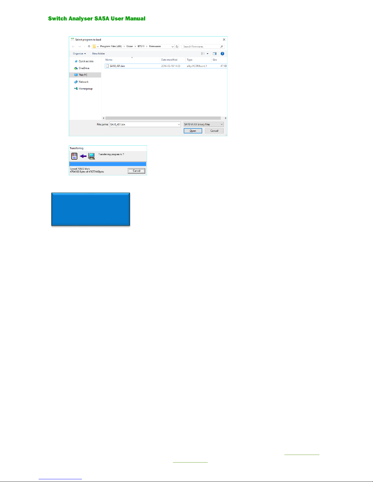
•A dialog will appear to download the software.
Select SA5A V5.XX binary files.
Select the program. “SA5A_xxx.bin”
Open the file with the command button “Open”
•The new software will now be transferred to the
Control unit. This may take a while.
•When finished the following dialog will appear.
6.8 SA5A PROGRAM LOADER IN DISPLAY.
When the display shows
•Something happened to the SA5A that made it lose its program.
•Connect the unit to computer and start BTS11.
•Select what comport unit is connected to.
•A dialog will automatically appear to download the software.
IMPORTANT! Select SA5A binary files in the dropdown list.
PROGRAM LOADER 5.11
2018-03-06
www.elcon.se
CPU = 43°PCB = 30°
Page 15 (24)
Rev 0 2018-04-20 www.elcon.se
Go to INDEX.
Open the file with the command button “Open”
•The new software will now be transferred to the Control unit. This may take a while.
When the display shows the following screen the SA5A is ready to use.
Ready for Close 31°
Uc 0 V= Uk 0 V=
Ul 0 V= Um 0 V=
Im 0.0 A=
Page 16 (24)
Rev 0 2018-04-20 www.elcon.se
Go to INDEX.
7.0 ADJUSTMENTS
7.1 INSTRUMENT NEEDED
DC-voltage source 1: ±0-250 V DC (used for calibration of motor and coil voltage)
DC-voltage source 2: 0 -5 V DC (used for calibration of transducers analog input)
DC-current source: 0-10 A (min) (used for calibration of motor and coil current)
Voltage instrument: 0 -300 VDC accuracy ± 0.2%
Current instrument: 0 -10 A (min) accuracy ± 0.2%
Computer: with the software BTS11 installed.
7.2 GENERAL
The calibration of SA5A is done with the software BTS11.
Refer to BTS11 User manual for operating instructions.
All analogue inputs on the SA5A are software calibrated.
Calibration can easy be done from a calibration guide.
All calibration constants and password for changing constants are saved in the SA5A.
NOTE!
Password at delivery is “elcon”
Principle of calibration
Two points are measured at abt.10 respective about 90% of full scale for selected input.
The values are measured with both the SA5A and a connected reference instrument.
With use of the equation for the straight line, new calibration constants are calculated.
INPUTS THAT SHALL BE CALIBRATED
Coil voltage "Uc"
Coil current "Ic"
Motor voltage "Um"
Motor current "Im"
Voltage input "Uk"
Voltage input "Ul"
Analog transducer "T1"
See paragraph 4. SPECIFICATION for input range and accuracy.
Page 17 (24)
Rev 0 2018-04-20 www.elcon.se
Go to INDEX.
7.3 GENERAL CALIBRATION PROCEDURE
•Select function "Control unit" from the menu "Service"
•Select command button ”Calibrate”
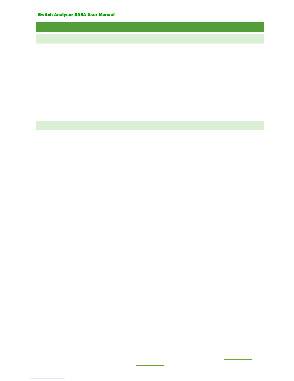
The following dialogue box is displayed:
The dialogue box has three tabs for different types of inputs.
The calibration constants for selected inputs are displayed.
For tab ”Analogue Inputs” are the inputs selected from a list box.
Note! Typing new values in the text boxes change the calibration constants immediately.
This is not recommended for tabs “Analog inputs”, “Transducers” and “Resistance”.
Use the command button ”Calibration wizard” instead.
Command buttons
“New Password” Change of current password (The password is saved in SA5A)
“Customer settings”: Set a customer instrument No for SA5A
“Calibration wizard” Start a calibration guide for selected inputs
“Print” Print all calibration constants for SA5A on a connected printer.
“Save” Save all changed calibration constants to SA5A
“Cancel” Close the dialog box.
The calibration procedure is almost the same for all inputs.
•Select tab for inputs to calibrate
•Press the command button ”Calibration wizard...” for starting the calibration guide
(Not available for tab “Time measurement”)
•Follow the instructions for each dialogue box in the wizard.

Page 18 (24)
Rev 0 2018-04-20 www.elcon.se
Go to INDEX.
7.3.1 CALIBRATION WIZARD FOR VOLTAGE MEASUREMENT ON ANALOGUE INPUTS:
Select tab “Analog inputs” from the dialogue box “Calibration SA5A”. See paragraph 6.3.
Select inputs to be calibrated form the list box.
Select command button “Calibration wizard”. The following dialogue box is displayed:
Calibration wizard
•Step 1.
Select a single analogue input or all analogue inputs to calibrate with the option buttons
If all voltage channels shall be calibrate at the same time the same voltage source must be connected to all selected
voltage inputs
Press the command button ”Next”.
•Step 2
Connect a stable DC-voltage source and a voltage instrument to the selected input.
Press the command button ”Next”.
Page 19 (24)
Rev 0 2018-04-20 www.elcon.se
Go to INDEX.
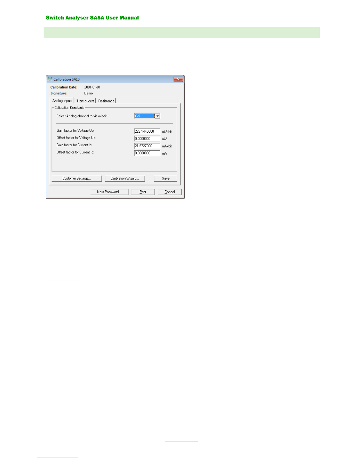
•Step 3.
Set the voltage source to about -200 V.
Enter the value (V) from the reference instrument.
Press the command button ”Next”
Note: The instrument box shows the voltage value from selected channel measured by the control unit SA5A
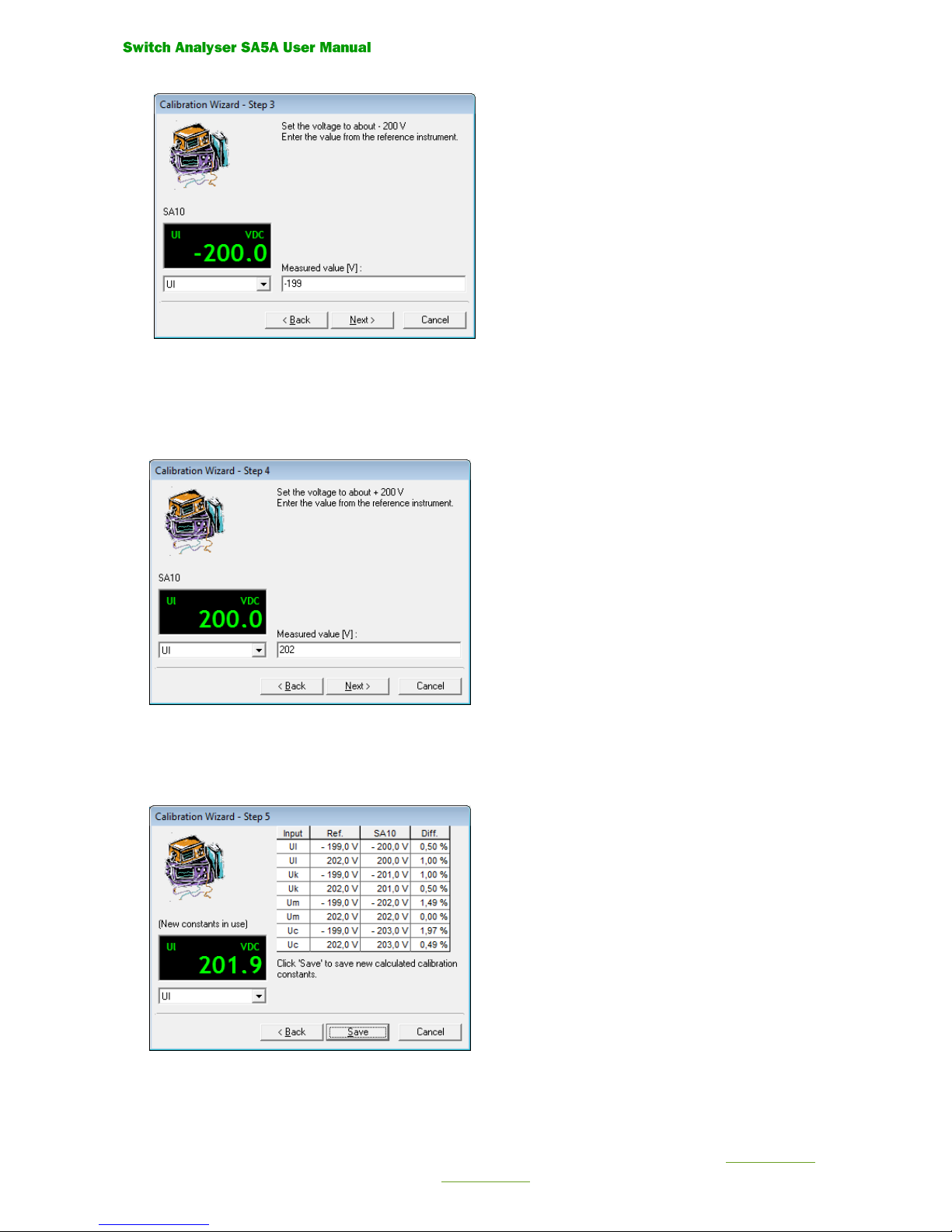
•Step 4.
Set the voltage source to about +200 V.
Enter the value (V) from the reference instrument.
Press the command button ”Next”
•Step 5
New calibration constants are now calculated
Select button ”Save” to save the new calculated calibration constants.
Select button “Cancel” to cancel the guide without updating the calibration constant.
Page 20 (24)
Rev 0 2018-04-20 www.elcon.se
Go to INDEX.
7.3.2 CALIBRATION WIZARD FOR CURRENT MEASUREMENT ON ANALOGUE INPUTS:
Select tab “Analog inputs” from the dialogue box “Calibration SA5A”. See paragraph 6.3.
Select inputs to be calibrated from the list box
Select command button “Calibration wizard”. The following dialogue box is displayed:
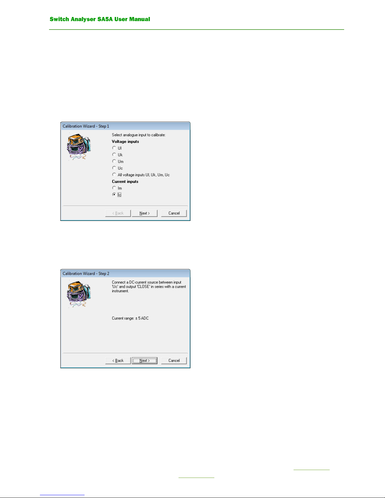
Calibration wizard
•Step 1.
Select current input to calibrate with the option button.
Press command button ”Next”.
•STEP 2
CONNECT A DC-CURRENT SOURCE TO INPUT “UC” AND TO OUTPUT “CLOSE” IN SERIES WITH A CURRENT
INSTRUMENT.
PRESS THE COMMAND BUTTON ”NEXT”.
Table of contents
Other Elcon Measuring Instrument manuals


Popular Measuring Instrument manuals by other brands

domat
domat THERMASGARD ATM 2 Operating Instructions, Mounting & Installation

PANCONTROL
PANCONTROL PAN Luxmeter manual

McCrometer
McCrometer McMag2000 Installation, operation and maintenance manual

Honeywell
Honeywell E-Mon Class 1000 quick start guide

Omron
Omron Z500-SW2T Setup manual

AVL
AVL F-FEM-CNT operating manual


PRECISION DIGITAL
PRECISION DIGITAL pd663 user manual

Sensidyne
Sensidyne SensAlarm Plus user manual

LANDTEC
LANDTEC Geotech G100 Series operating manual

Rohde & Schwarz
Rohde & Schwarz R&S FPL1000 Getting started

Salter Labs
Salter Labs RO2 check quick start guide

Hanna Instruments
Hanna Instruments HI 96762C instruction manual