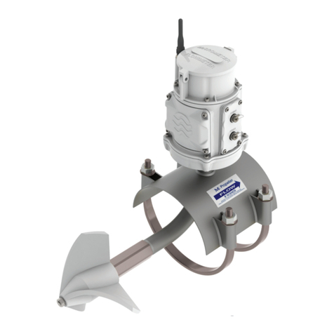
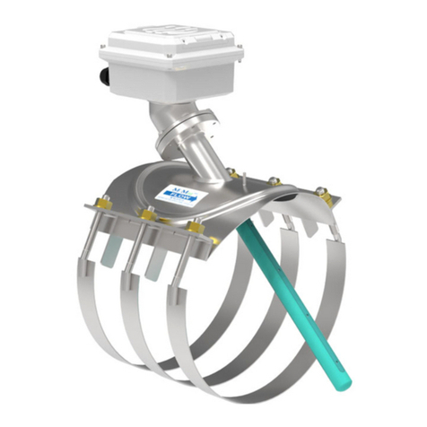
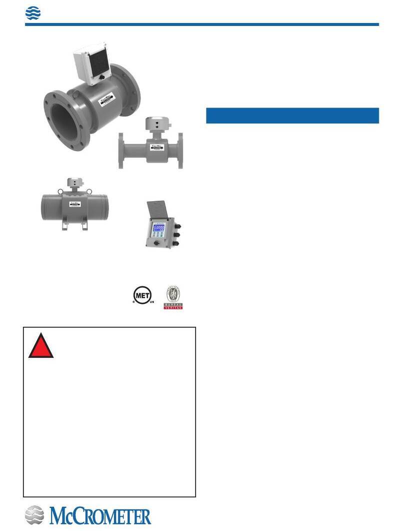
McCrometer McMag2000 User manual
Other McCrometer Measuring Instrument manuals
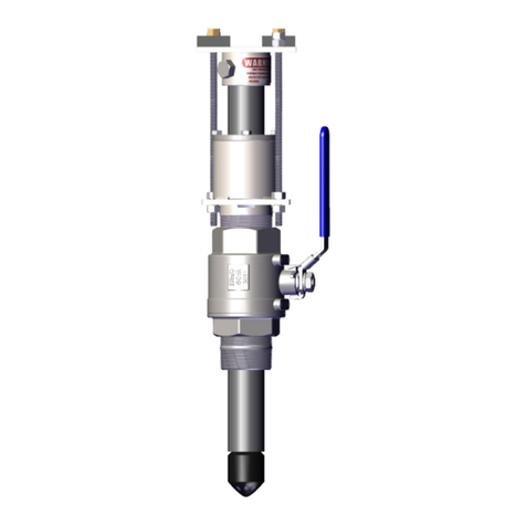
McCrometer
McCrometer SPI Mag 282L User manual
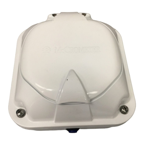
McCrometer
McCrometer DURA MAG McMag 3000 Instruction Manual
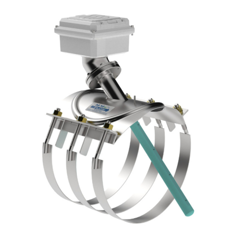
McCrometer
McCrometer McMag3000 Instruction Manual
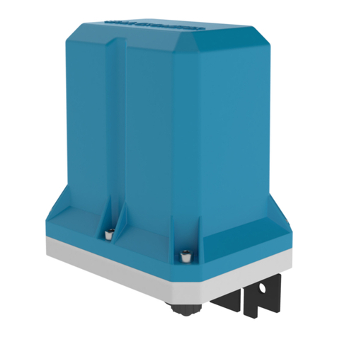
McCrometer
McCrometer SmartTrax User manual
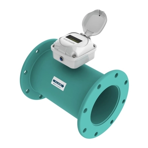
McCrometer
McCrometer Dura Mag Instruction Manual

McCrometer
McCrometer Mc Mag3000 User manual

McCrometer
McCrometer FPI Mag 394 User manual
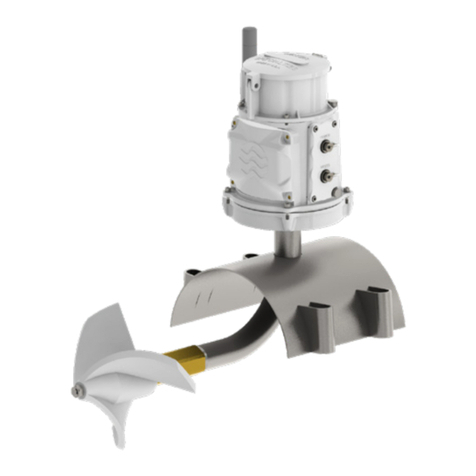
McCrometer
McCrometer FlowConnect User manual
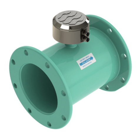
McCrometer
McCrometer ULTRA MAG UM06 User manual
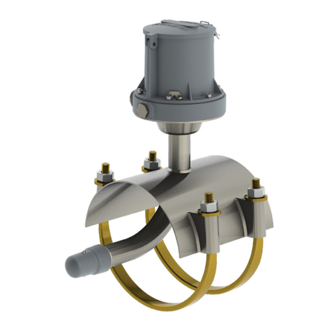
McCrometer
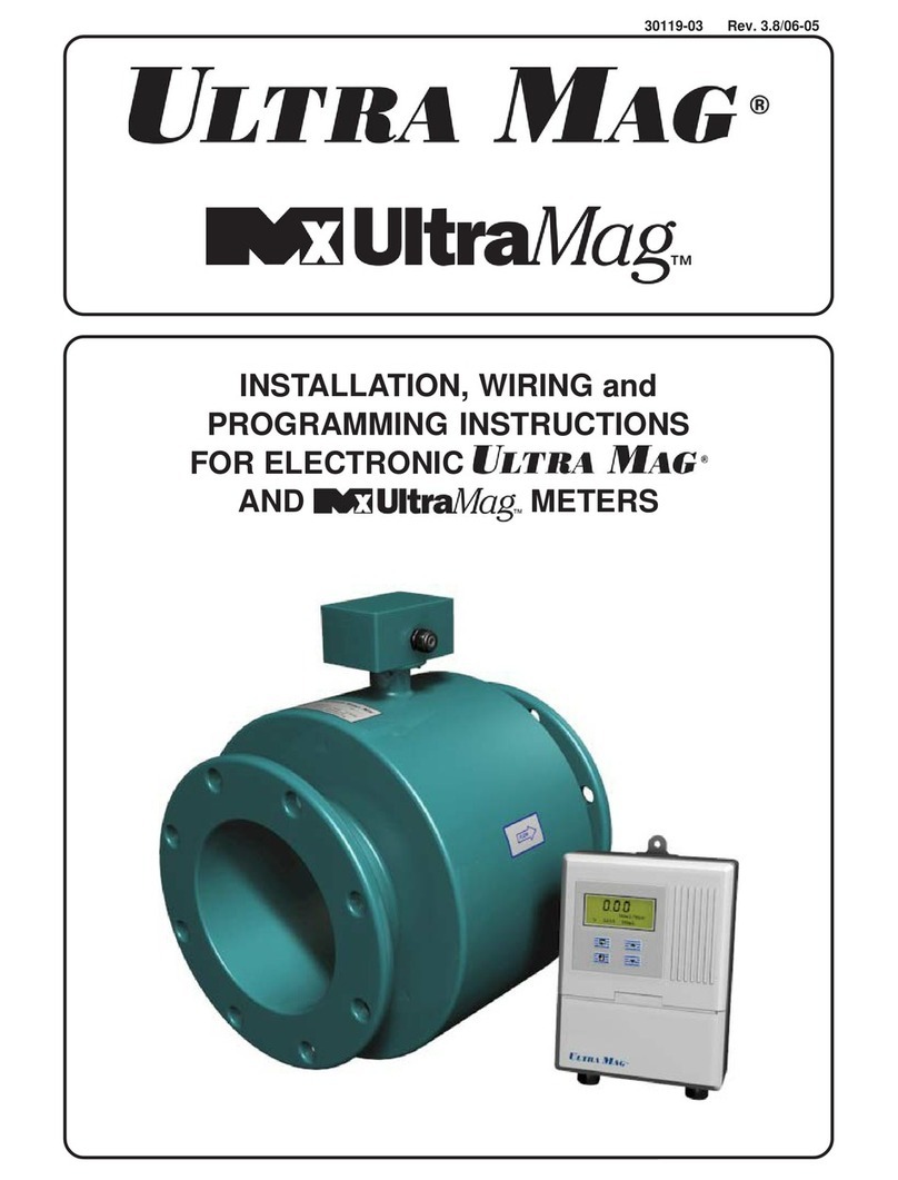
McCrometer McMag2000 User manual
McCrometer
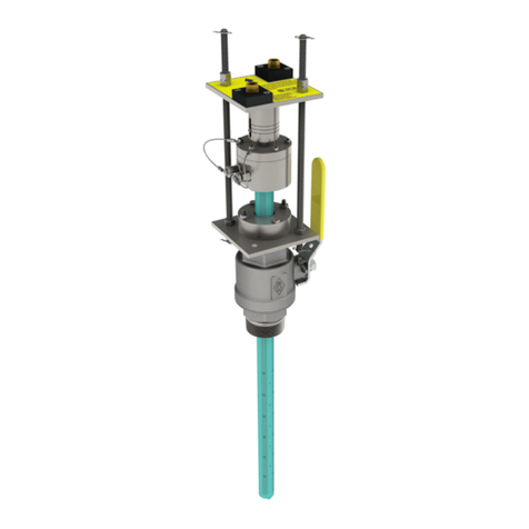
McCrometer Ultra Mag User manual
McCrometer
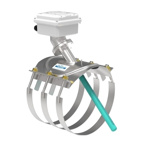
McCrometer FPI Mag 394L User manual
McCrometer
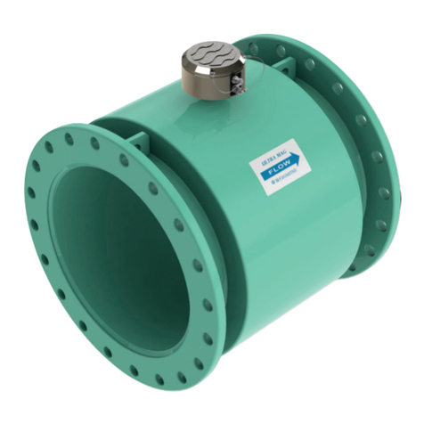
McCrometer Mc Mag3000 User manual
McCrometer
McCrometer ULTRA MAG 4 User manual
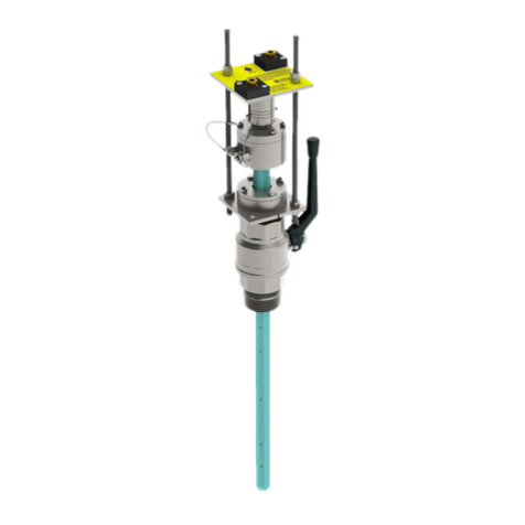
McCrometer
McCrometer FPI Mag 394E User manual

McCrometer
McCrometer SPI Mag 282L User manual
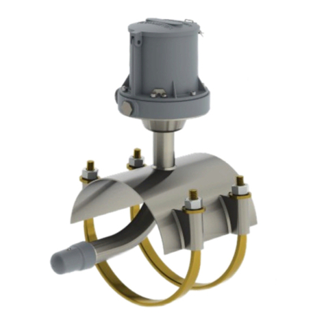
McCrometer
McCrometer McMAG 2000 Instruction Manual

McCrometer
McCrometer Dura Mag User manual

McCrometer
McCrometer FPI Mag 394L User manual
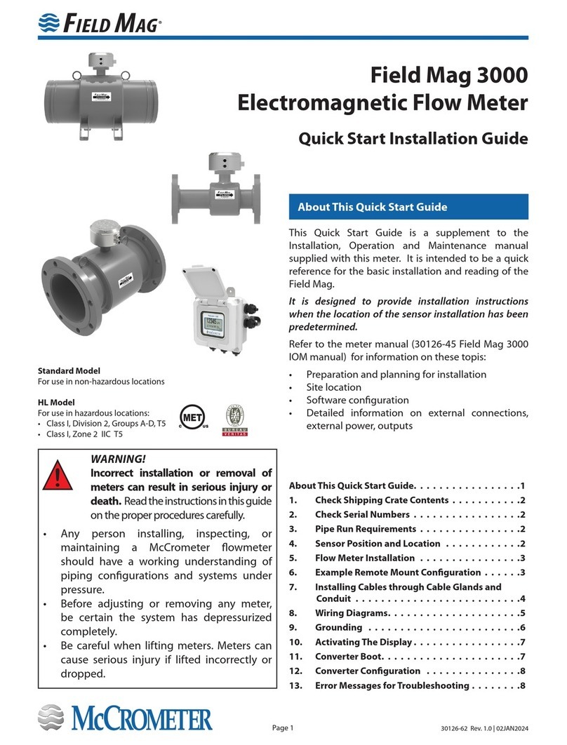
McCrometer
McCrometer Field Mag 3000 Instruction Manual
Popular Measuring Instrument manuals by other brands

Powerfix Profi
Powerfix Profi 278296 Operation and safety notes

Test Equipment Depot
Test Equipment Depot GVT-427B user manual

Fieldpiece
Fieldpiece ACH Operator's manual

FLYSURFER
FLYSURFER VIRON3 user manual

GMW
GMW TG uni 1 operating manual

Downeaster
Downeaster Wind & Weather Medallion Series instruction manual

Hanna Instruments
Hanna Instruments HI96725C instruction manual

Nokeval
Nokeval KMR260 quick guide

HOKUYO AUTOMATIC
HOKUYO AUTOMATIC UBG-05LN instruction manual

Fluke
Fluke 96000 Series Operator's manual

Test Products International
Test Products International SP565 user manual

General Sleep
General Sleep Zmachine Insight+ DT-200 Service manual
