ELCOS CBS-031 Instruction Manual

CBS -031 CBS-061 - EN 1
®
PARMA
ITALY
E-mail: info@elcos.it - HTTP://www.elcos.it
Fax +39 0521/270218
Tel. +39 0521/772021
SUITABLE TO BE INSTALLED ALSO ON BOARD THE MACHINE
In this case the standard mounting position is recommended
INSTRUCTION AND USER MANUAL
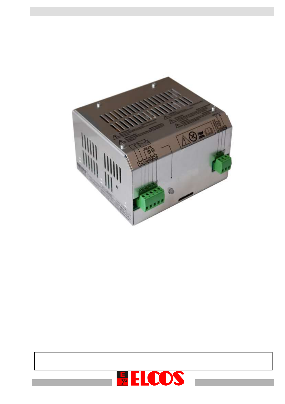
AUTOMATIC BATTERY CHARGERS
FOR LEAD BATTERIES
TYPE CBS - 031 (3,5A) 12V
CBS - 061 (6A)
with the DIN 41773 Standard
THREE CHARGING LEVELS
- RAPID WITH CURRENT CONTROL
- INTERMEDIATE
- MAINTENANCE
THE BATTERY CHARGER SIGNALS THE FOLLOWING CONDITION:
•SHORT CIRCUIT
•POLARITY INVERSION
•BATTERY CABLE DISCONNECTION
- SERIAL OUTPUTS RS485
- REMOTE REPETITION FOR INDICATOR LIGHTS
- ALSO WITH OMEGA RAIL HOOK MOUNTING IN FRONT (STANDARD) OR AT
THE SIDE
- ENERGY SAVING
WITH VOLTAGE CONTROL
}

CBS-031 CBS-061 - EN
2
TECHNICAL DATA
CBS
-
031
CBS
-
061
Battery
voltage: 12V 12V 24V
Power supply
85V~÷ 265V~ 185V~ ÷ 265V~
Insulation class
Class I
Nominal
charge
current:
3,5A 6A
Connectable
battery:
Open lead, sealed
lead, 6 cell gel (minimum
cap
acity 30 Ah)
Open lead, sealed
lead, 6 cell gel (minimum
capacity 60 Ah)
Maximum
absorbed
power at
230V:
60W 110W 220W
Full charging
ouput 75% 88%
Circuit loading
in absence
of mains supply:
15mA 18mA 36mA
Max. load
on outputs
11, 12 e 14:
3W
Typical voltage
on output 11:
14V
14V
28V
Terminal board:
8 Poles with screw
Degree of
protection: IP 00
Temperature
range:
- 10 ÷ 50 °C
Weight gr.
350
600
700
Energy saving
(Absorbed
power without
load)
1,5W
2W
2W
CBS -031 CBS-061 - EN 3
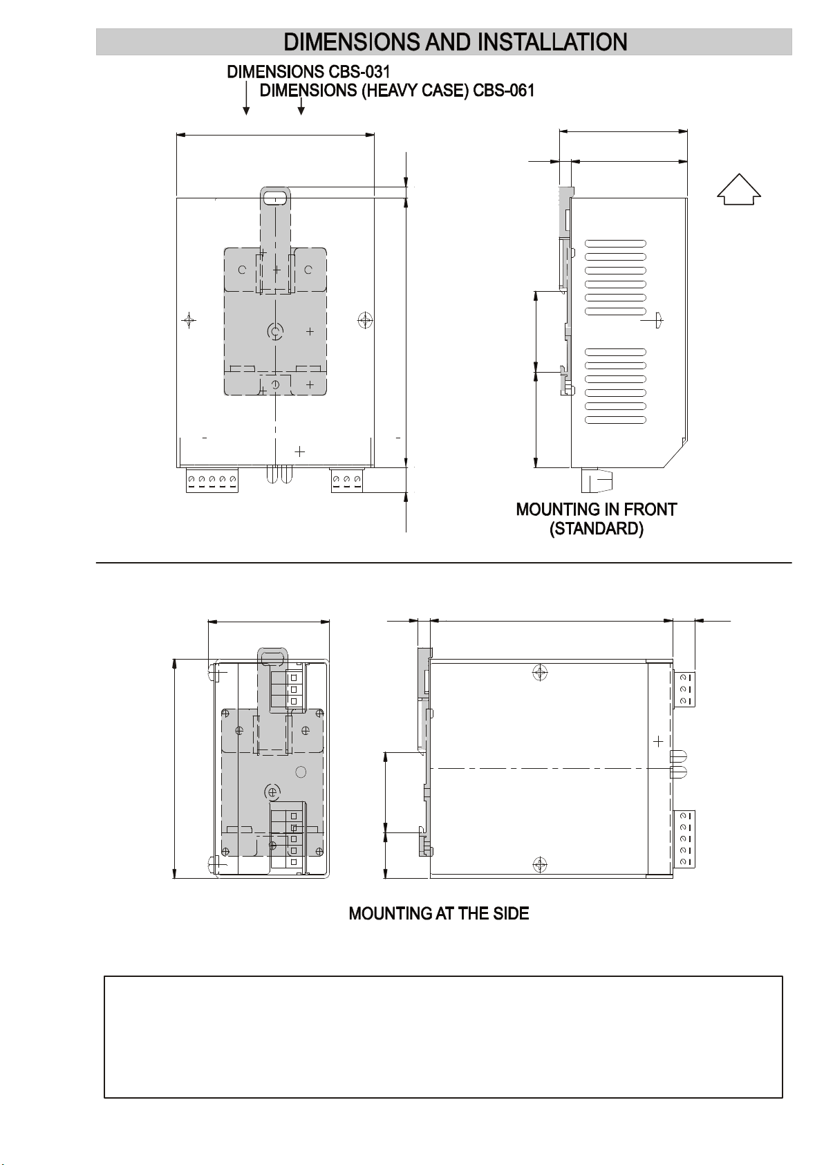
• During the charging phase the equipment heats up. One must therefore ensure that the natural
flow of air is not obstructed by nearby objects.
• If the equipment is installed in a closed cabinet, holes or slits should be provided so that the heat
can escape.
To mount at the side, move the OMEGA bar hook support (highlighted) to the
position shown on the drawing.
HIGH
97
123
63
83
57
77
6
6
35
35
42
42
119
119
5
5
11
11
60
78
97
140
20
42
35
35
6
6
119
119
11
11

CBS-031 CBS-061 - EN
4
OPERATION
AUTOMATIC CHARGING
Automatic charging takes place at four levels:
1. Rapid charge via current control 3,5A (CBS-031), 6A (CBS-061), until 14 V (28 V) (±
4%) are reached in the battery.
2. Intermediate charge via voltage control, until14,4 V, (28,8 V) (± 4%) are reached in
the battery.
3. Maintenance charge using a very low current value, but sufficient to maintain the
voltage value at 13,5 (o 27 V) (± 4%).
a. With battery voltage between 13.5 V and 13.7 V (27 V) the battery charger does
not carry out adjustments
b. With battery voltage higher than 13,7 V (27,4 V) V the battery charger
decreases the supply of current.
c. With battery voltage lower than 13.5 V (27 V) the battery charger tries to
maintain this voltage by supplying current
d. Starts again with fast charging (point 1) with battery voltage lower than 11,5 V
(23V) (+/-4%).
4 Recovery of the battery unloads. The battery is recharged to impulses with pauses of
20 second between a package and the other signals.
SIGNALS
The GREEN LED is lit when the following conditions happen at the same time:
• mains on
• battery voltage above 1,5 V
RED LED is lit (flashing code) when at least
one of the following conditions happens:
NUMBER OF FLASHES FOLLOWED BY
PAUSE
- MAINS FAILURE 1
- BATTERY CABLES
DISCONNECTED (with engine stationary) 2
- SHORT CIRCUITING OF THE BATTERY
CABLES 3
The remote signals repetition is available on terminals 11, 12 and 14:
The load connected between terminals 11 and 12 is supplied when the green signal is lit;
The load connected between terminals 11 and 14 is supplied when the red signal is lit;
SERIAL COMMUNICATION PORT RS485
Serial output for transmission of data on the state of the battery to the prepared control unit
Data sent
•Battery voltmeterer
•Load current ammeter
•Battery charger status (see signals)
If there is overloading of the remote repetition terminals or if there is a mains failure, both of the
indicators will remain unlit.

CBS -031 CBS-061 - EN 5
L11N
MAINS
230V~
CHARGE
CBS-031
CBS-061
1 2 11 12 75 7614
A NO M A LY
MAX 3 W
WIRING DIAGRAM
TYPICAL LOAD CURVES
•
Devices must be provided for disconnection from the mains: for example, switches
with contacts opening greater than 3 mm or supply cables and plugs which are
also accessible after installation.
V/I
I
V
Rapid charge Intermediate charge
14,4 V
14 V
Maintenance charge
(28,8 V)
(28 V)
13,5 V (27 V)
SERIAL TWIN WIRE CONNECTION
(male)
•
•
•
• • • • •
•
•
•
Only suitably trained electrical personnel may make this connection.
Take out the two terminal boards
Insert the twin wire connector in the serial connector
Close the cover
Insert the terminals boards
Switch off the mains voltage
Remove the cover
Insert the terminal board
• • • • •
WARNING
NEVER SUPPLY POWER TO THE BATTERY
CHARGER WITH THE COVER NOT INSTALLED CORRECTLY
!
FUSE
2A (CBS-031)
3,15A (CBS-061)
FUSE
6A (CBS-031)
10A (CBS-061)

CBS-031 CBS-061 - EN
6
NOTICES
Used only to maintain the battery charge. Used in the starting circuits of diesel and petrol
engines, such as those used in genset units, close-coupled pumps, compressor motors, etc.
Constructed for installation only inside the electric panel.
Warning:
Adhere closely to the following advice
•Install in such a way that there is always adequate heat disposal.
•Always install under other equipment which produces or spreads heat.
•Adhere to the instructions indicated for installation.
•Check that the absorption and consumption of the connected equipment are compatible with
the enclosed technical characteristics.
•Do not try to recharge non rechargeable batteries.
•When charging lead batteries, place the battery in a well-aired area.
•The connection to the mains must be made in accordance with the national installation rules.
•The equipment must be earthed via the relevant terminal.
•Connect the equipment to the battery without other conductor cutouts.
•Disconnect the equipment output terminals before any interventions on the battery.
•Make sure that no copper conductor cuttings or other waste material fall inside the equipment.
THIS BATTERY CHARGER IS NOT SUITABLE FOR OPERATING IN THE FOLLOWING CONDITIONS:
•Where the environmental temperature is outside the limits indicated in the technical data.
•Where the air pressure and temperature variations are so rapid as to produce exceptional
condensation.
•Where there are high levels of pollution caused by dust, smoke, vapour, salts and corrosive or
radioactive particles.
•Where there are high levels or heat from radiation caused by the sun, ovens or the like.
•Where attacks from mould or small animals are possible.
•Where there is the risk of fire or explosions.
•Where the battery charger can receive strong vibrations or knocks.
•Where the equipment is protected by barriers or casing with protection level less than IP40.
ELECTROMAGNETICCOMPATIBILITY
This battery charger functions correctly only if inserted in plants which conform with the CE marking
standards; it meets the exemption requirements of the standard EN61326-1 but it cannot be excluded
that malfunctions could occur in extreme cases due to particular situations.
The installer is responsible for checking whether the levels of disturbance are above those consented
by the regulations.
CONDUCTION AND MAINTENANCE
The following maintenance operations should be performed every week:
- check that the indicators function;
- check the batteries;
- check that the conductors are tight, check the condition of the terminals.
UNLESS WE MAKE A WRITTEN DECLARATION STATING THE CONTRARY, THIS EQUIPMENT
IS NOT SUITABLE FOR USE AS A CRITICAL COMPONENT IN EQUIPMENTS OR PLANTS
RESPONSIBLE FOR KEEPING PERSONS OR OTHER LIVING BEINGS ALIVE.
YOUR ELECTRICAL TECHNICIAN CAN ASK ANY QUESTIONS ABOUT
THIS EQUIPMENT BY TELEPHONING OUR TECHNICIAN

CBS -031 CBS-061 - EN 7
Warning: Components carrying dangerous voltage levels
Only assigned and suitably trained personnel are allowed to have battery charger access.
No maintenance operations are permitted unless the plant has been disconnected from
the mains and from the battery. The phases should be earthed and short-circuited as a
safety measure. Notwithstanding what is stated above, only assigned and trained
personnel, when the plant is live, can perform the following operations:
· visual inspection of the battery charger, the connections and the markings;
· measurement of voltage and/or current values.
These operations must, in any case, be performed using a tool which guarantees the appropriate
electrical protection.

CBS-031 CBS-061 - EN
8
Type Code
CBS-031 12V 00010440
CBS-061 12 V 00010444
CBS-061 24V 00010445
ORDERING INFORMATION
ACCESSORIES KIT
KIT MU-CBS-030/060 40804413
This manual suits for next models
1
Table of contents
Other ELCOS Batteries Charger manuals

Popular Batteries Charger manuals by other brands


WATSON
WATSON AA-8LCD owner's manual

Bosch
Bosch BC330 Operating/safety instructions

Bayan Audio
Bayan Audio Mixx In Car DASHCHARGE quick start guide

Global Technology
Global Technology Six-bay Multi-chemistry Charger Operation manual

Chargery
Chargery 320B operating instructions

Philips
Philips SCB4050NB user manual