Elditest GE Series User manual

GE Series
Passive Voltage Oscilloscope Probes
User Manual

Elditest
2
www.sefram.com
Table of Contents
Safety Summary........................................................................ 4
Introduction .............................................................................. 6
Accessories................................................................................ 8
Probe Compensation...................................................................13
Specifications..................................................................................14
Voltage Derating Curve ...............................................................17
Cleaning.................................................................................... 20
Service & Warranty Information...................................................21
Prescriptions de sécurité..............................................................23
Mise en oeuvre........................................................................... 25
Pièces détachées ........................................................................27
Compensation de la sonde...........................................................31
Spécifications..................................................................................33
Courbe de relation Tension / Fréquence.........................................36
Nettoyage..................................................................................39
Informations sur la maintenance et la garantie ............................ 40
Allgemeine Sicherheitsinformation ............................................. 42
Einleitung.................................................................................. 44
Austauschteile........................................................................... 46
Tastkopf Kompensation ............................................................. 50
Technische Daten ...................................................................... 52
Spannungs / Frequenz Derating Kurve..........................................55
Reinigung.................................................................................. 58
Service- und Gewährleistungsinformationen................................ 59
Service...................................................................................... 60
Maintenance, ajustage............................................................... 60
Bedienung................................................................................. 60

Elditest
www.sefram.com
3

Elditest
4
www.sefram.com
GE Series Oscilloscope Probe User Manual
© Cal Test Electronic, Inc. All rights reserved.
Elditest is an authorized brand name for these probe products. Unauthorized
duplication of this documentation material is strictly prohibited. Customers are
permitted to duplicate and distribute thisdocumentation for internal educational
purposes only.
Made in Taiwan
Safety Notice and Symbols
This product is designed to IEC/EN 61010-031 safety requirements for electrical
equipment for measurement, control and laboratory use: Handheld probe assemblies
The following symbols may appear on the product or in its documentation:
CAUTION A caution statement calls attention to an operating procedure,practice,
or condition, which, if not followed correctly, could result in damage
to or destruction of parts or the entire product.
WARNING A warning statement calls attention to an operating procedure,
practice, or condition, which, if not followed correctly, could result in
injury or death to personnel.
Caution Symbol (ISO 7000-0434) –Statements or
instructions that must be consulted in order to find out
the nature of the potential hazard and any actions
whichmust be taken.
Caution –possibility of electric shock.

Elditest
www.sefram.com
5
Disposal
(Applicable in the European Union and other European countries with
separate collection systems). This product is subject to Directive
2012/19/EU of the European Parliament and the Council of the
European Union on waste electrical andelectronic equipment (WEEE),
and in jurisdictions adopting that Directive, is marked as being put on
the market after August 13, 2005, and should not be disposed of as
unsorted municipal waste. Please utilize your local WEEE collection
facilities in the disposition of this product.
CE Compliance
This product meets the essential requirements of the applicable EuropeanDirectives as
follows:
•Low-Voltage Directive (safety): 2014/35/EU
Standard IEC/EN61010-031:2015 (Second Edition)
•Restriction of Hazardous Substances Directive (RoHS): 2011/65/EU
Standard EN50581:2012
Safety Summary
To avoid personal injury and/or product damage, review and comply with the
following safety precautions. These precautions apply to both operatingand
maintenance personnel and must be followed during all phases of operation, service,
and repair of this probe.
Comply with Voltage Derating Curve
WARNING When measuring higher frequency signals, be sure to comply
with the Voltage vs Frequency Derating Curve. Do not apply to
the input any potential that exceeds themaximum rating of
the probe.
Dry Conditions
WARNING Hands, shoes, floor, and work bench must be dry. Avoid
making
measurements under humidity, dampness, or other
environmental conditions that might affect safety.

Elditest
6
www.sefram.com
Hazardous Contact
WARNING To avoid injury, remove jewelry such as rings, watches,
and other
metallic objects. Do not touch exposed connections and
components when power is present.
Use Only in Office-Type Indoor Setting
These probes are designed to be used in office-type indoor environments.Do not
operate:
•In the presence of noxious, corrosive, flammable fumes, gases, vapors,
chemicals, or finely-divided particulates.
•In environments where there is a danger of any liquid being spilled onthe
probe.
•In air temperatures exceeding the specified operating temperatures.
•In atmospheric pressures outside the specified altitude limits or wherethe
surrounding gas is not air.
Only Qualified Personnel
These probes are intended for personnel who are trained, experienced, or otherwise
qualified to recognize hazardous situations and who are trained inthe safety
precautions necessary to avoid possible injury when using such
a device.
Must be Grounded
CAUTION Use only with test instruments having their BNC input
connected to earth ground. Always properly ground the
oscilloscope probe with its ground lead before connecting to
circuits. Always disconnect the probe fromcircuits before
disconnecting the ground lead. Do not connect the probe
ground lead to any point which is at apotential other than earth
ground.

Elditest
www.sefram.com
7
Introduction
The GE Series of high impedance, passive voltage oscilloscope probes are
designed for use with most general-purpose oscilloscopes having an
input impedance of 1 MΩ shunted by 13 pF, however selected models maybe
compensated for use with instruments having an input capacitance between 10 to
30 pF. Models with RA suffix are compatible with readout function oscilloscopes that
automatically detect probe attenuation and adjust their readout scale accordingly.
Table 1:Probe Models 1500 and 2500 series
Model
Attn.
Bandwidth
(MHz)
Max Input
Voltage
(DC + AC peak)
Comp.range
(pF)
Length
(m)
GE1511
10x
150
500 V CAT II
10-30
1.2
GE1521
1x/10x
17/150
1.2
GE2511
10x
250
500 V CAT II
10-30
1.2
GE2521
1x/10x
25/250
1.2

Elditest
8
www.sefram.com
Table 2:Probe Models 3100, 3200, 3400, and 4500 series
Model
Attn.
Bandwidth
(MHz)
Max Input
Voltage
(DC + AC peak)
Comp.range
(pF)
Length
(m)
GE3121
100x
150
2 kV CAT II
10-30
1.2
GE3421
100x
100
4 kV CAT II
10-30
1.2
GE4511
10x
500
500 V CAT II
6-22
1.2
Initial Inspection
This unit is tested prior to shipment. It is therefore ready for immediate use upon
receipt. An initial inspection should be made to ensure that nodamage has been
sustained during shipment. After the inspection, verifythe contents of the
shipment.

Elditest
www.sefram.com
9
Accessories
Figure 1: Accessory Diagram
Table 3:List of Included Accessories
Item
CT Part #
Description
Quantity
1
CT2709A-#
Sprung Hook, 5 mm, Red
1
2
CT2710-12-0
GND Lead w/Alligator Clip
1
3
CT2708a
BNC Adapter, 5 mm
1
4
CT2711A-0a
CT3823-0b
Replacement Tip, Black
1
5
CT3648
Deluxe Trimmer Tool
1
6
CT2713A-#a
IC Tip Insulator, 5 mm, Black
1
7
CT2712A-#a
Tip Insulator, 5 mm, Black
1
8
CT4408-#
Probe Tip Cover, 5 mm,
1
9
CT3662
Color Coding Rings (Blue,
Green, Red, Yellow)
2 each
10
CT2714a
Probe Tip GND
1
a: Only for 1500, 2500, and 4500 series
b: Only for 3100, 3200, and 3400 series

Elditest
1
0
www.sefram.com
To use or replace accessories use the following guides.
Sprung Hook
The sprung hook snaps directly onto the probe over the probe tip. Pushfirmly until
you feel it snap into place. If the sprung hook is not snappedinto place it could fall
off or significantly degrade signal quality during measurements.
Figure 2: Sprung Hook Attachment
Ground Lead w/ Alligator Clip
The 12 cm ground lead inserts directly into the side of the probe. The added length
means added inductance and this must be taken into accountfor accurate
measurements.
Figure 3: Ground Lead w/ Alligator Clip Attachment

Elditest
10
www.sefram.com
BNC Adapter
The BNC adapter fits directly onto the probe over the probe tip.
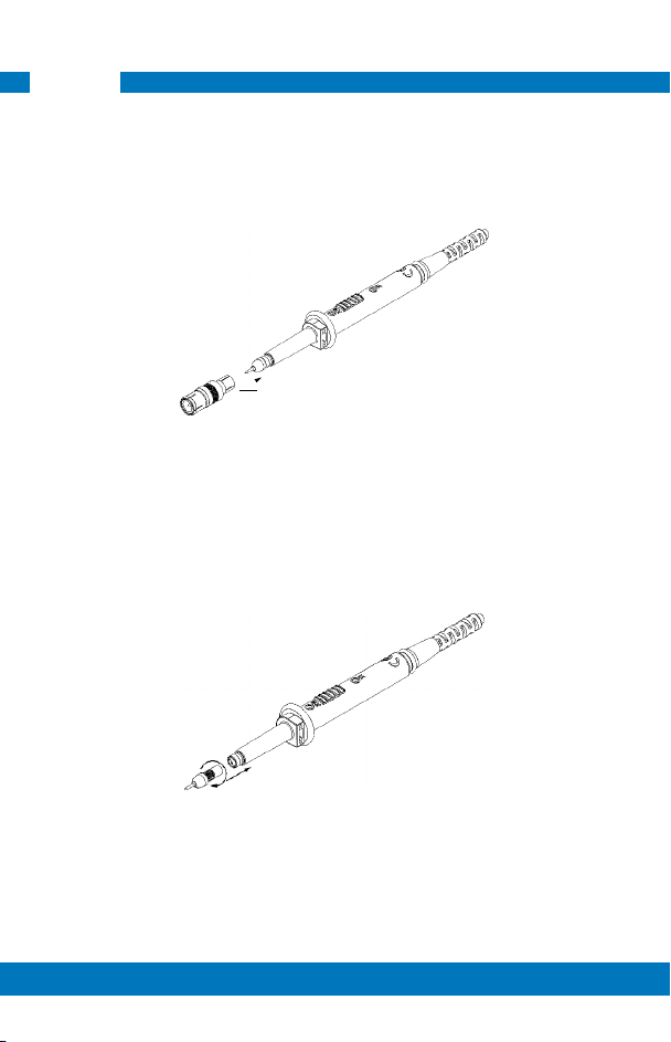
Probe Tips
Figure 4: BNC Adapter Attachment
The rigid probe tip screws into the probe end. (CT3823-0 not shown,attaches the
same way)
Figure 5: Probe Tip Attachment

Elditest
www.sefram.com
11
Tip Insulators
The tip insulators fit directly onto the probe over the probe tip.
Figure 6: Tip Insulators Attachment
Color Coding Rings
The matching color coding rings snap directly onto the back of the BNC connectorand at
the back end of the probe body.
Figure 7: Color Coding Ring Attachment

Elditest
12
www.sefram.com
Probe Tip Ground
The probe tip ground fits directly onto the probe over the probe tip.
Figure 8: Probe Tip Ground Attachment

Elditest
www.sefram.com
13
Probe Compensation
Proper compensation of the probe is required to assure amplitude accuracy of the
waveform being measured by matching the probe to theoscilloscopes input
capacitance. Low frequency compensation should be adjusted whenever the
probe is connected to or transferred betweenoscilloscopes.
Procedure:
Low Frequency (LF):
•Apply a 1 kHz square wave to
the probe or connect to the
oscilloscope’s calibrator
output.
•Adjust the trimmer located onthe
probe body (LF) for a flat topped
square.
Figure 9: LF Compensation
Over Compensated
Incorrect
Under Compensated
Incorrect
Properly Compensated
Correct
Figure 10: LF Waveform Compensation

Elditest
14
www.sefram.com
High Frequency (HF):
(Should seldom require adjustment, however, if adjustment is required)
•Apply a 1 MHz square wave to the probe (<0.7 ns rise-time)
•Adjust the trimmer located on the probe body (HF) toward the cableend for
a flat topped square wave for the GE2500 series.
•Adjust the trimmer located on the BNC box (HF) for a flat toppedsquare
wave for the GE4500 series.
Over Compensated
Incorrect
Under Compensated
Incorrect
Properly Compensated
Correct
Figure 11: HF Waveform Compensation
Specifications
All specifications apply to the unit after a temperature stabilization time of20
minutes over an ambient temperature range of 25°C ± 5°C.
Table 4:Electrical Characteristics 1500 Series
Electrical Characteristics
Model
Attn.
Input
Impedance
(MΩ / pF)
BW
(MHz)
Rise
Time
(ns)
Max Voltage
(DC + ACpeak)
Voltage
Coefficient
(VCR)
Comp.
Range
(pF)
GE1511
10x
10/12
150
2.3
500 V CAT II
≤ 1.5
ppm/V
(2%)
10-30
GE1521
1x
10x
1/45
10/12
17
150
20
2.3

Elditest
www.sefram.com
15
Table 5: Electrical Characteristics 2500, 3100, 3200, 3400 and 4500 series
Electrical Characteristics
Model
Attn.
Input
Impedance
(MΩ / pF)
BW
(MHz)
Rise
Time
(ns)
Max Voltage
(DC + ACpeak)
Voltage
Coefficient
(VCR)
Comp.
Range
(pF)
GE2511
10x
10/12
250
1.4
500 V CAT II
≤ 1.5
ppm/V
(2%)
10-30
GE2521
1x
10x
1/45
10/12
25
250
14
1.4
GE3121
100x
100/5
150
2.3
2 kV CAT II
≤ 30 ppm/V
(6%)
GE3421
100x
100/5
100
2.3
4 kV CAT II
≤ 30 ppm/V
(6%)
10-30
GE4511
10x
10/10
500
0.7
500 V CAT II
≤ 0.5 ppm/V
(1%)
6-22

Elditest
16
www.sefram.com
Table 6: Mechanical Characteristics
Mechanical Characteristics
Weight
Approx. 70 g
Cable Length
1.2 m or 2 m
Probe Barrel Diameter (ground point)
5 mm
Table 7: Environmental Characteristics
Environmental Characteristics
Operating Temp
0°C to 50°C
Storage Temp
-30°C to 70°C
Operating Altitude
Up to 3000 meters
Humidity
85% RH (at 35°C)
Pollution Degree
2
Table 8: Safety Specifications
Specifications are subject to change without notice. To ensure the most currentversion of this
manual, please download the current version from our website: caltestelectronics.com.
IEC/EN 61010-031:2015 (Second Edition)
Safety Specifications

Elditest
www.sefram.com
17
Voltage (Vrms)
Voltage Derating Curve
The derating curve of the absolute maximum input voltage is shown asfollows:
Maximum Input Voltage Derating Curve
1000
500
GE150c0, 2500, & 4500
Series
100
50
10
10 kHz
100 kHz
1 MHz
10 MHz 100 MHz
1 GHz
Frequency
Figure 12: GE1500, GE2500, and GE4500 Series Voltage Derating Curve

Elditest
18
www.sefram.com
Voltage (DC+ACpeak)
Maximum Input Voltage Derating Curve
10 kV
4 kV
2 kV
GE3400 Series
1 kV
GE3100 & 3200 Series
200 V
0
10 kHz
100 kHz 1 MHz 10 MHz
100 MHz
1 GHz
Frequency
Figure 13: GE3000 Series Voltage Derating Curve
WARNING Do not exceed the voltage or category rating of theprobe
WARNING To avoid electric shock, keep fingers behind the probe’sfinger guard
during use.
WARNING Probe assemblies must not be used for measurementson mains
circuits.
This manual suits for next models
7
Table of contents
Languages:
Other Elditest Measuring Instrument manuals


