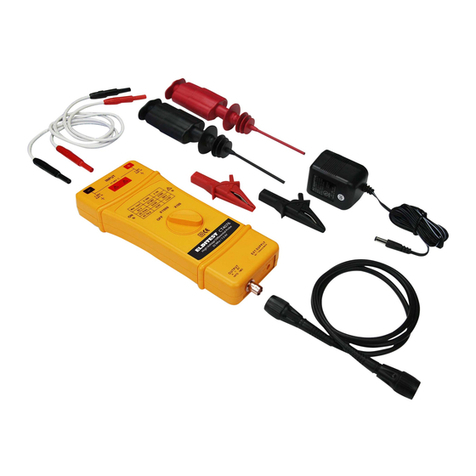
Elditest CP6000 Series User manual


CP6000MAN v01
1
TABLE OF CONTENTS
English Section 3
Warranty 4
General Safety Instructions 4
Safety Terms and Symbols 5
Compliance Information 6
Description 8
Basic Operation 9
Maintenance 12
Specifications 14
Kit Contents 17
Section Française 19
Garantie 20
Prescriptions de sécurité 20
Termes et symboles de sécurité 21
Conformité aux normes 22
Description 24
Mise en œuvre 25
Maintenance 28
Specifications 30
Contenu du Kit 33
German Section 35
Gewährleistung 36
Allgemeine Sicherheitshinweise 36
Sicherheitsbegriffe und Symbole 37
Compliance Information 38
Beschreibung 41
Basisbetrieb 42
Wartung 45
Technische Daten 47
Umfang Des Dausatzes 50

CP6000MAN v01
2

CP6000MAN v01
3
ENGLISH SECTION
© 2013 All rights reserved.
ELDITEST is atrademark of Sefram Instruments and Systems.
ELDITEST products are covered by US and foreign patents, issued and pending.
Information in this publication supersedes all earlier versions. Specifications
subject to change without notice.
For product information, sales, service and technical support:
North America:
Cal Test Electronics, Inc.
22820 Savi Ranch Pkwy.
Yorba Linda, CAUSA
Europe:
SEFRAM Instruments et Systèmes
32, rue E. MARTEL BP55
F 42009 – SAINT-ETIENNE Cedex 2France

CP6000MAN v01
4
WARRANTY
ELDITEST warrants its probes for normal use and operation within specification
for a period of one (1) year from the date of shipment (accessories and manual
not included).
In exercising its warranty, ELDITEST, at its option, will either repair or replace
any assembly returned within the warranty period. However, this will be done
only if the product is determined by ELDITEST’s examination to be defective
because of workmanship or materials, and the defect is not caused by misuse,
neglect, accident, abnormal conditions of operation, or damaged by attempted
repair or modifications by non-authorized facility.
The customer will be responsible for the transportation and insurance charges for
the return of products.
This warranty replaces all other warranties, expressed or implied, including, but
not limited to, any implied warranty of merchantability, fitness, or adequacy for
any particular purpose or use. ELDITEST shall not be liable for any special,
incidental or consequential damages, whether in contract or otherwise.
This electronic product is subject to disposal and recycling
regulations that vary by country and region. Many countries
prohibit the disposal of waste electronics equipment in standard
waste receptacles.
Made in Taiwan
GENERAL SAFETY INSTRUCTIONS
Read the following safety instructions to avoid injury and prevent damage to this
product or any products connected to it. Use this product only as specified.
Only qualified personnel should perform service procedures.
To Avoid Fire or Personal Injury
Connect and Disconnect Properly: Connect the probe output to the
measurement instrument before connecting the probe to the circuit under test.

CP6000MAN v01
5
Disconnect the probe input and the probe ground from the circuit under test
before disconnecting the probe from the measurement instrument.
Observe All Terminal Ratings: To avoid fire or shock hazard, observe all rating
and markings on the product. Consult the instruction manual for further ratings
information before making connections to the product.
Replace Batteries Properly: Replace batteries only with the proper type and
rating specified.
Do Not Operate Without Covers: Do not operate this product without the
covers or panels.
Avoid Exposed Circuitry: Do not touch exposed connections and components
when power is present.
Do Not Operate With Suspected Failures: If you suspect there is damage to
this product, have it inspected by qualified service personnel.
Do Not Operate in Wet/Damp Conditions.
Do Not Operate in an Explosive Atmosphere.
Keep Product Surfaces Clean and Dry
SAFETY TERMS AND SYMBOLS
• Terms in This Manual. These terms may appear in this manual:
WARNING. Warning statements identify conditions or practices that
could result in injury or loss of life.
CAUTION. Caution statements identify conditions or practices that
could result in damage to this product or other property.
• Terms on the Product. These terms may appear on the product:
DANGER indicates an injury hazard immediately accessible as you read the
marking.

CP6000MAN v01
6
WARNING indicates an injury hazard not immediately accessible as you read the
marking.
CAUTION indicates a hazard to property including the product.
• Symbols on the Product. These symbols may appear on the product:
Attention refers to operation Instructions.
This instrument has double insulation.
COMPLIANCE INFORMATION
This section lists the safety, and environmental standards with which the probes
comply.
SAFETY COMPLIANCE
EC Declaration of Conformity – Low Voltage
Compliance was demonstrated to the following specification as listed in the
Official Journal of the European Union:
Low Voltage Directive 73/23/EEC, as amended by 93/68/EEC.
EN 61010-1/A2:1995 – Safety requirements for electrical equipment for
measurement control and laboratory use.
EN 61010-2-032:1995 – Particular requirements for hand-held current clamps for
electrical measurement and test equipment.
ADDITIONAL COMPLIANCES
EN 61010-1/A2:1995 – Safety requirements for electrical equipment for
measurement control and laboratory use.

CP6000MAN v01
7
EN 61010-2-032:1995 – Particular requirements for hand-held current clamps for
electrical measurement and test equipment.
POLLUTION DEGREE DESCRIPTION
A measure of the contaminants that could occur in the environment around and
within a product. Typically the internal environment inside a product is considered
to be the same as the external. Products should be used only in the environment
for which they are rated.
Pollution Degree 1. No pollution or only dry, nonconductive pollution occurs.
Products in this category are generally encapsulated, hermetically sealed, or
located in clean rooms.
Pollution Degree 2. Normally only dry, nonconductive pollution occurs.
Occasionally a temporary conductivity that is caused by condensation must be
expected. This location is a typical office/home environment. Temporary
condensation occurs only when the product is out of service.
Pollution Degree Pollution Degree 2 (as defined in IEC 61010-1). Note: Rated
for indoor use only.
INSTALLATION (OVERVOLTAGE)
CATEGORY DESCRIPTIONS
Terminals on this product may have different installation (overvoltage) category
designations. The installation categories are:
Measurement Category I. For measurements performed on circuits not directly
connected to MAINS.
Measurement Category II. For measurements performed on circuits directly
connected to the low-voltage installation.
Measurement Category III. For measurements performed in the building
installation.
Overvoltage Category. Overvoltage Category II (as defined in IEC 61010-1)

CP6000MAN v01
8
DESCRIPTION
The CP6000 family of AC/DC current probes enables oscilloscope instruments to
display AC, DC, and AC+DC current measurements up to 100 amps peak
(CP6220) and frequencies up to 1.5 MHz (CP6990). Using supplied BNC to
Banana plug adapter (CT3956) the current probes will work with most modern
Digital Multimeter (DMM).
Figure 1: Controls and indicators on current probe
CLAMP PROBE CONTROLS AND INDICATORS
CURRENT FLOW SYMBOL
Arrow on current jaws shows the probe’s polarity convention for measuring
current flowing from positive to negative.
DC ZERO ADJUST
Rotate to adjust the probe output to zero when there is no current present. It may
also be used to offset a DC signal component. Zeroing is not needed for AC
measurements unless your instrument cannot isolate a DC component, if present.
Current Flow
Symbol
BNC Female
Output
Jaw Opening Lever
OFF/Range
Switch
Wire Clamp
BNC Female
Output
AC Adapter
Input
DC Zero Adjust
ON Indicator
Overload Indicator

CP6000MAN v01
9
OFF/RANGE SWITCH
Slide the switch from OFF to either the low or high measurement range. When
either range is selected, the probe is turned on, and the green battery indicator
lights. If the indicator does not light, see Battery and AC Power Adapter and
Battery Installation.
ON INDICATOR
The ON indicator lights green when the probe is turned on. For more information,
see Battery and AC Power Adapter and Battery Installation.
OVERLOAD INDICATOR
The overload indicator lights red if the measured signal is greater than the
selected range capability. Switch the probe to higher measurement range, if
possible, or remove the probe from the circuit.
BASIC OPERATION
Before using the probe a battery or specified power adaptor must be installed.
See Battery and AC Power Adapter and Battery Installation.
WARNING!
Do not clamp the probe onto circuits with voltages greater than 600 VAC (600V
CAT II, 300V CAT III). Personal injury or damage to the probe may result.
Always connect the current probe to an instrument before clamping onto the
circuit under test.
1. Connect the BNC cable (CT3955-100) to the current probe’s BNC female
output connector then connect the BNC cable to the oscilloscope’s BNC input.
Start by setting the oscilloscope’s voltage input channel to DC and the voltage
sensitivity to 0.1 V/div.
2. Move the OFF/Range switch to the low V/A or high V/A position. The green
ON Indictor LED will light. If the green ON Indictor LED does not light, replace
the battery or use included power adaptor.
3. Use the ZERO Adjust to zero or offset the probe output of residual magnetic
DC charges.
4. Connect the probe to the circuit by opening the jaws with the Jaws Opening
Lever and clamping around the conductor. See Figure 2.

CP6000MAN v01
10
Figure 2: Connecting the current probe
5. Adjust the oscilloscope’s channel amplitude and time base settings as
necessary to get a clear and stable signal. Set the oscilloscope input to DC volts
to see both the AC and DC currents; set the channel to AC to see the AC current
only. The current drawn by selected devices can vary. While the RMS current
can only be used in low frequency current, the transient peaks can be quite high.
Figure 3 shows the difference between a line current drawn by a resistive load
and a motor controller.
Figure 3: Typical current waveforms
When connecting the current probe to a Digital Multimeter (DMM), use the
included BNC-to-banana adapter (CT3956). Connect the black banana plug on
the adapter to the DMM’s COM or ground jack and the red banana plug to the
VΩjack.
To measure only AC current, set the meter to measure AC volts. To measure
DC current, set the meter to measure DC volts.
Resistive load
Motor controller

CP6000MAN v01
11
NOTE: the current convention arrow on the probe to get the proper polarity
reading.
NOTE: clamping around both the “hot” and “neutral” wires may give a zero
reading.
To increase the measurement sensitivity of the current probes, loop additional
turns of the wire under test through the jaws. See Figure 4. The sensitivity of the
current probe is multiplied times the number of loops in the jaws. For example:
200 mV/A X 4 turns = 800 mV/A.
Figure 4: Increasing the sensitivity
Remember to unclamp the probe from the conductor before disconnecting it from
your meter or instrument.

CP6000MAN v01
12
MAINTENANCE
Use the information in this section to properly maintain the operation of your
AC/DC Current Probe.
BATTERY AND AC POWER ADAPTER
A CP6000 Series current probe uses a single 9 V battery. As the probe is a high
power product, please use the specified alkaline battery.
As the battery installed is drained, a significant gain error may occur. The green
ON Indicator LED will continue to light until a low battery voltage of 6.5 V is
reached. If probe gain errors are detected, replace the battery.
The included AC Power Adapter can be used to avoid gain error due to a low
battery. Use the AC Power Adapter when there is AC power available.
The CP6000 Series current probes have in their design a priority external power
circuit, therefore it is safe to use the AC Power Adapter while the battery is
installed. However, when using the AC Power Adapter for an extended period,
removal of the battery is recommended.
BATTERY INSTALLATION
(1) Remove the probe from the circuit.
(2) Open the battery compartment by loosening and removing the three screws
on the back of the probe. Lift off the back cover.
(3) Observing polarity, attach the new alkaline battery to the connector buttons
and place the battery into the compartment, as illustrated in Figure 5.
(4) Replace the back cover and lightly tighten the three cover screws.

CP6000MAN v01
13
Figure 5: Battery Installation
CLEANING
• Clean only the exterior of the probe, cables and accessories. Use a soft cotton
cloth moistened with a mild detergent and water solution. To clean the core,
open the jaw and clean the exposed core surfaces with a cotton swap dampened
with isopropyl alcohol. Lubricate the jaws mating surfaces with light oil. Do not
allow any portion of the probe to be submerged at any time.
• Dry the probe and accessory thoroughly before attempting to make any current
measurements.
• Do not subject the probe to solvents or solvent fumes as these can cause
deterioration of the probe body, cables and accessories.

CP6000MAN v01
14
SPECIFICATIONS
MODEL
CP6220
CP6550
CP6770
CP6990
Measurement Ranges
100 mV/A – 10
mV/A
200 mV/A – 20
mV/A
500 mV/A – 50
mV/A
1 V/A – 100
mV/A
Current (DC + peak AC)
10 A – 100 A
5 A – 50 A
7 A – 70 A
4 A – 40 A
DC Measurement
Accuracy
±3% ±50 mA
@ 100 mV/A
(50 mA to 10 A
peak)
±4% ±50 mA
@ 10 mV/A
(500 mA to 40
A peak)
±15% max @
10 mV/A (40 A
peak to 100 A
peak)
<±3% ±30 mA
@ 200 mV/A
(30 mA to 5 A
peak)
±4% ±300 mA
@ 20 mV/A
(300 mA to 20
A peak)
±15% @ 200
mV/A (20 A
peak to 50 A
peak)
<±3% ±20 mA
@ 500 mV/A
(20 mA to 14 A
peak)
±4% ±200 mA
@ 50 mV/A
(200 mA to
100 A peak)
±15% @ 50
mV/A (100 A
peak to 140 A
peak)
<±3% ±10 mA
@ 1 V/A (10
mA to 8 A
peak)
±4% ±100 mA
@ 100 mV/A
(100 mA to 80
A peak)
Bandwidth
DC – 300 kHz
DC – 500 kHz
DC – 1 MHz
DC – 1.5 MHz
Phase Shift
See Graph
9(a)
See Graph
9(b)
See Graph
9(c)
See Graph
9(d)
Rise and Fall Time
1.2 µs (typ.)
0.7 µs (typ.)
0.35 µs (typ.)
0.23 µs (typ.)
Max. Working Voltage
600 VAC RMS CAT II / 300 VAC RMS CAT III
Max. Floating Voltage
600 VAC RMS CAT II / 300 VAC RMS CAT III
Battery Type
9 V Alkaline (NEDA 1604A, IEC 6LR61)
Typ. Battery Life
8 h
6 h
4 h
Operating Temp.
0 to 50°C (32 to 122°F)
Storage Temp.
-20 to 80°C (-4 to 176°F)
Max. Operating Humidity
0 to 95% (0 to 40°C; 32 to 104°F)
0 to 45% (40 to 50°C; 104 to 122°F)
Max. Cable Diameter
11 mm (0.43”)
10.3 mm (0.4”)
Dimensions
262 mm x 79 mm x 36 mm
(10.3 x 3.15 x 1.4”)
262 mm x 81 mm x 36 mm
(10.3 x 3.2 x 1.4”)
Weight
260 g w/o battery
310 g w/o battery

CP6000MAN v01
15
100 mV/A range
10 mV/A range
Gain in dB
Frequency (Hz)
100 1K 10K 100K 1M
0
-1
-2
-3
-4
-5
300K30K
Gain in dB
Frequency (Hz)
100 mV/A range
10 mV/A range
Gain in dB
Frequency (Hz)
200 mV/A range
20 mV/A range
Gain in dB
Frequency (Hz)
50 mV/A range
500 mV/A range
Gain in dB
Frequency (Hz)
0.1 mV/A range
1 mV/A range
Figure 6(a – d): Gain versus Frequency @ 1 A peak, typical
6(a)
6(b)
6(c)
6(d)
Peak
current
RMS
current
Frequency (Hz)
0A
10A
20A
30A
40A
50A
60A
70A
80A
0A
7A
14A
21A
28A
35A
42A
49A
56A
10 100 1K 10K 100K 500K 1M
Peak
current
RMS
current
Frequency (Hz)
0A
20A
40A
60A
80A
100A
120A
140A
160A
0A
14A
28A
42A
56A
70A
84A
98A
112A
10 100 1K 10K 100K 300K 1M
Peak
Current
Frequency (Hz)
Frequency (Hz)
Figure 7(a – d): Maximum Current versus Frequency
7(a)
7(b)
Peak
Current
RMS
Current
RMS
Current
Peak
Current
Frequency (Hz)
7(c)
RMS
Current
Peak
Current
Frequency (Hz)
7(d)
RMS
Current

CP6000MAN v01
16
50 mV/A range
10 mV/A range
100 mV/A range
Frequency
(Hz)
500 mV/A range
0.1 V/A range
1 V/A range
20 mV/A range
200 mV/A range
9(a)
9(b)
9(c)
9(d)
Phase in
degrees
Frequency
(Hz)
Frequency
(Hz)
Frequency
(Hz)
Phase in
degrees
Phase in
degrees
Phase in
degrees
Figure 9(a - d): Phase versus Frequency @ 1 A peak, typical
Uncertainty %
Amperes (A)
Typical
Specification
0 10 20 30 40 50
-16
-14
-12
-10
-8
-6
-4
-2
0
Uncertainty %
Amperes (A)
Typical
Specification
0 20 40 60 80 100
-16
-14
-12
-10
-8
-6
-4
-2
0
Uncertainty %
Amperes (A)
Typical
Specification
0 20 40 60 80 100
-16
-14
-12
-10
-8
-6
-4
-2
0
Uncertainty %
Amperes (A)
Typical
Specification
0 10 20 30 40 50
-16
-14
-12
-10
-8
-6
-4
-2
0
Uncertainty %
Amperes (A)
Figure 8(a – d): DC Signal Linearity in the 0.1 V/A range, typical
8(a)
Specification
Typical
Uncertainty %
Amperes (A)
8(b)
Typical
Specification
Uncertainty %
Uncertainty %
Amperes (A)
Amperes (A)
Typical
Typical
Specification
Specification
8(c)
8(d)

CP6000MAN v01
17
KIT CONTENTS
Unpack the probe and check that you received all items listed.
Probe – CP6000 Series
BNC to BNC Coaxial Cable – CT3955-100
BNC to Banana Plug Adapter – CT3956
AC Power Adapter:
North American (NA) – CT3957-NA
European (EU) – CT3957-EU
Instruction Manual (multilingual) – CP6000MAN

CP6000MAN v01
18
This manual suits for next models
4
Table of contents
Languages:
Other Elditest Measuring Instrument manuals

