electric bike solutions EBS V2 User manual

Operating instructions
EBS Display Mini - Dot Matrix - V2
Operating Instructions EBS Display Mini - Dot-Matrix - V2, Version V1.0 Copyright © 2018 by Electric Bike Solutions GmbHPage 1
Operating instructions
EBS V2 Operating Display Mini
with black / white dot matrix display
and integrated control element
Item no.: aelcdky-01

Operating instructions
EBS Display Mini - Dot Matrix - V2
Operating Instructions EBS Display Mini - Dot-Matrix - V2, Version V1.0 Copyright © 2018 by Electric Bike Solutions GmbHPage 2
Table of contents
1 About this guide.................................................................................................................................................3
2 Scope of delivery................................................................................................................................................3
3 Appearance and size ..........................................................................................................................................3
3.1 Material and operating parameters ..........................................................................................................3
3.2 Dimensions ................................................................................................................................................3
4 Function overview..............................................................................................................................................4
4.1 Displayable values in driving mode ...........................................................................................................4
4.2 Control element.........................................................................................................................................4
4.3 Quick start: Adjustable values ...................................................................................................................5
5 Mounting the display on the handlebar ............................................................................................................5
6 Setting the display before the first ride .............................................................................................................7
6.1 Switch on display .......................................................................................................................................7
6.2 Setting wheel size and maximum speed with motor assistance ...............................................................7
7 Operating the display while driving ...................................................................................................................9
7.1 Switching on and off..................................................................................................................................9
7.2 Display of current speed, TRIP, ODO, Ridtime, AVG and MAX ................................................................10
7.3 Choice of support level............................................................................................................................11
7.4 6 km/h pushing aid ..................................................................................................................................11
7.5 Dimming the display lighting and switching it on again ..........................................................................12
7.6 Power display in bar form........................................................................................................................12
7.7 Battery charge level indicator..................................................................................................................12
8 For experienced users: Making individual settings via the display ..................................................................13
8.1 General Settings ......................................................................................................................................13
8.1.1 1-Clear Trip: Resetting the short trip counter "TRIP". .....................................................................14
8.1.2 2-Set Unit: Distance and Speed Units..............................................................................................14
8.1.3 3-Set WD: Impeller size.................................................................................................................... 15
8.1.4 4-Set LS: Maximum speed with motor assistance ........................................................................... 15
8.1.5 5-Set Voltage: Battery status display and undervoltage switch-off.................................................16
8.2 Advanced settings, "Specific Set..............................................................................................................17
8.2.1 1-Power Set: Number of support levels and current level setting per support level ......................17
8.2.2 2-Current Set: Maximum current ....................................................................................................19
8.2.3 3-Assistant num: Number of magnets in the PAS disc.....................................................................19
8.2.4 4-Speed Sensor: Number of spoke magnets ...................................................................................20
8.2.5 5-Slow Start: Start-up delay............................................................................................................. 20
8.2.6 6-Backlight Set: Backlight................................................................................................................. 21
8.2.7 7-Password Set: Power-on protection password ............................................................................21
8.3 Resetting to the display manufacturer's factory settings ..........................................................................23
9 Troubleshooting...............................................................................................................................................24
9.1 Error message..........................................................................................................................................24
9.2 Error codes ..............................................................................................................................................24
10 Frequently asked questions .............................................................................................................................25
11 Safety instructions ...........................................................................................................................................26
12 Customer service..............................................................................................................................................26
13 Disposal............................................................................................................................................................26
14 Imprint .............................................................................................................................................................27

Operating instructions
EBS Display Mini - Dot Matrix - V2
Operating Instructions EBS Display Mini - Dot-Matrix - V2, Version V1.0 Copyright © 2018 by Electric Bike Solutions GmbHPage 3
1About this guide
These instructions are an integral part of the product. They contain important information and safety instruc-
tions. Therefore, keep the manual handy at all times and pass it on to third parties if you pass on the product!
For the safe and successful commissioning of your EBS V2 Mini operating display, please be sure to read this ma-
nual and observe the safety instructions!
2Scope of delivery
The scope of delivery of the display includes:
•EBS V2 operating display Mini with:
-black / white dot matrix display
-Integrated 3-way push-button / control element
-in the 36 Volt version
- Bracket for handlebars with 22.2 mm diameter
-Item no.: aelcdky-01.
3Appearance and size
3.1 Material and operating parameters
•The housing of the display is made of scratch- and break-resistant plastic.
•Operate the unit only within a temperature range of - 20°C to + 60°C.
3.2 Dimensions
•Display with integrated control element:
All dimensions in mm.
22,2
44
46
56
32

Operating instructions
EBS Display Mini - Dot Matrix - V2
Operating Instructions EBS Display Mini - Dot-Matrix - V2, Version V1.0 Copyright © 2018 by Electric Bike Solutions GmbHPage 4
4Function overview
4.1 Displayable values in driving mode
The display can give you information about:
•Battery charge level
•active support level
•Current speed
•Average speed (AVG)
•Maximum speed (MAX)
•Time since last switch-on (Ridtime)
•Daily kilometres (TRIP)
•Total kilometres (ODO)
•6 km/h pushing aid (P)
•Display lighting
•Error codes (ERR)
•Graphic power display by means of bars
4.2 Control element
•The display is equipped with an integrated control element with 3 buttons:
... is referred to as UP.
... is referred to as DOWN.
... is referred to as MODE.
Battery charge level
DOWN
Support level
Speed
Unit
Power
MODE
UP

Operating instructions
EBS Display Mini - Dot Matrix - V2
Operating Instructions EBS Display Mini - Dot-Matrix - V2, Version V1.0 Copyright © 2018 by Electric Bike Solutions GmbHPage 5
4.3 Quick start: Adjustable values
You can make the following settings on the display:
General settings within the so-called "General Settings" (chapter➔8.1):
Switch on the display, then press UP and DOWN simultaneously and hold for 2 seconds. The following parame-
ters can now be called up with UP or DOWN:
•TRIP: 1-Clear Trip Reset
•Distance and speed units: 2-Set Unit
•Impeller size: 3-Set WD
•Maximum speed with motor assistance: 4-set LS
•Battery status display and low-voltage cut-off: 5-Set Voltage
-After selecting one of the parameters, briefly press MODE.
-Change the parameter value by means of UP or DOWN.
-To save the stored value and exit the menu, press and hold the MODE button for 2 seconds.
Advanced settings within the so-called "Specific Settings" (chapter➔8.2):
Switch on the display, then press UP and DOWN simultaneously and hold for 2 seconds. Then press UP and DOWN
again simultaneously and keep them pressed for 2 seconds. The following parameters can now be called up with
UP or DOWN:
•Number of support levels and current level setting per support level: 1-Power Set
•Maximum current: 2-Current Set
•Number of magnets in the PAS disc: 3-Assistant num
•Number of spoke magnets: 4-speed sensor
•Start-up delay: 5-Slow Start
•Backlight: 6-Backlight Set
•Power-on protection password: 7-Password Set (with password "1212").
-After selecting one of the parameters, briefly press MODE.
-Change the parameter value by means of UP or DOWN.
-To save the stored value and exit the menu, press and hold the MODE button for 2 seconds.
Reset to the display manufacturer's factory settings (chapter➔8.3):
Switch on the display, then press MODE and UP simultaneously and hold for 2 seconds. Select "YES" with UP or
DOWN. Then press MODE for 3 seconds and keep it pressed.
5Display mounting on the handlebar
•Locate a suitable mounting location for the display on the left or right side of the handlebar. Ideally, the dis-
play should be mounted between the handlebar grip and the brake.
Tip: We offer various optional handlebar adapters for mounting the display in our web shop. You can find
them by searching for "handlebar adapter" in the PRODUCT SEARCH field on our website http://www. ebike-
solutions.com.
•Unscrew the fastening screw on the display completely using a 3 mm Allen key.
•Unfold the clamp on the display and place it around the handlebar. Make sure that the DOWN button points
to the left when viewed in the direction of travel.

Operating instructions
EBS Display Mini - Dot Matrix - V2
Operating Instructions EBS Display Mini - Dot-Matrix - V2, Version V1.0 Copyright © 2018 by Electric Bike Solutions GmbHPage 6
•Align the display so that you can read it easily later when driving and so that you do not have to take your
hand off the handlebar grip to operate the display buttons safely while driving.
•Replace the screw you have just removed and tighten it carefully with the Allen key. Caution: Do not over-
tighten the screw!
•The result is as follows:
-Display mounting on the left-hand side of the handlebar:
-Display mounting on the right-hand side of the handlebar:
•Now make sure that the power supply is switched off before connecting the display to the overall system
(cable distributor) via the display connection cable.
•To connect the display to the overall system (cable distributor), please observe the explanations in the as-
sembly instructions of your conversion kit.
•Then check again that the display is correctly connected to the cable distributor.

Operating instructions
EBS Display Mini - Dot Matrix - V2
Operating Instructions EBS Display Mini - Dot-Matrix - V2, Version V1.0 Copyright © 2018 by Electric Bike Solutions GmbHPage 7
6Setting the display before
the first ride
The display is already pre-configured. Neverthel-
ess, you have to enter various default values in the
display once before the first ride. This concerns,
for example, the tyre diameter of your wheel or
the maximum speed with motor assistance.
The display then "works" with these default values
you have set.
In addition, you can carry out fine-tuning via the dis-
play in order to adapt the behaviour of your conver-
sion set even better to your needs. These setting
options, however, intervene very deeply in the pro-
gramming. Therefore, before customising these pa-
rameters, you should always follow the instructions
in chapter (➔8).
In the following we will show you how to store the
appropriate values for your bike in the display.
Please observe the regulations of the StVZO or the
legal requirements regarding the maximum per-
mitted speed in your country.
6.1 Switch on display
Before you can configure the display individually,
you must switch it on.
To switch on the display, proceed as follows:
•Switch on the power supply (battery).
•Press and hold the MODE button for 1 second:
The display switches on:
Note: For better readability, the display entries in the
coloured online version of this manual have been co-
loured blue. In reality, however, these entries are
black and white.
6.2 Adjusting wheel size and maxi-
mum speed with motor as-
sistance
To correctly store the correct wheel size and maxi-
mum speed with motor assistance in the display be-
fore the first ride, proceed as follows:
•Switch on the display (chapter➔6.1).
•Press and hold both UP and DOWN buttons si-
multaneously for 2 seconds:
The display changes to settings mode. You can
recognise this by the following display entry:
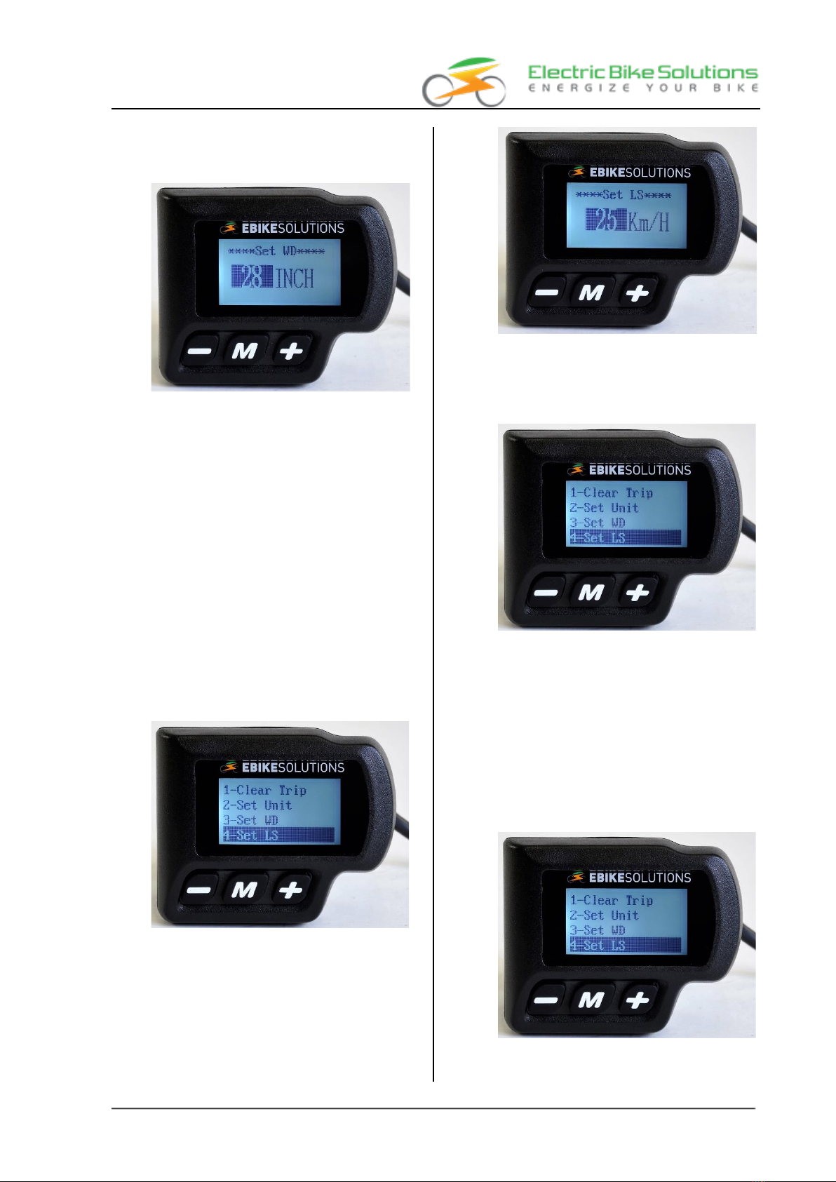
•Press UP twice to call up the entry "3-Set WD":
Operating instructions
EBS Display Mini - Dot Matrix - V2
Operating Instructions EBS Display Mini - Dot-Matrix - V2, Version V1.0 Copyright © 2018 by Electric Bike Solutions GmbHPage 8
•Press MODE briefly and the display jumps to a
wheel size such as "28 INCH", with the number
highlighted in dark:
Note: The value with a dark background is the
currently selected value.
•With UP or DOWN you can switch between the
individual options (here impeller sizes) if requi-
red.
The following can be selected: 08", 09", 10", ...,
26", 700 C, 28", 29", ..., 32". The value "700 C" is
suitable for road bikes.
•Once you have selected the appropriate value
for your wheel, briefly press MODE to confirm:
The display confirms a successful saving process
with the message "OK! The display then returns
to the setting mode shown above. "3-Set WD" is
stored again.
•Press UP briefly to highlight "4-Set LS":
•Press MODE briefly and the display will jump to
a speed value such as "25 Km/H", with the num-
ber highlighted in dark:
•If you are riding a pedelec and the value "25
Km/H" is stored, briefly press MODE to confirm:
The display acknowledges this with "OK!" and
then jumps back to "4-Set LS":
•If you ride a pedelec and a value other than "25
Km/h" is stored, you must select the entry "25"
via DOWN or UP:
Press DOWN to decrease the displayed value,
press UP to increase it.
•If the entry "25" is stored, press MODE briefly to
confirm:
The display acknowledges this with "OK!" and
then jumps back to "4-Set LS":
•Press and hold MODE for 2 seconds:

Operating instructions
EBS Display Mini - Dot Matrix - V2
Operating Instructions EBS Display Mini - Dot-Matrix - V2, Version V1.0 Copyright © 2018 by Electric Bike Solutions GmbHPage 9
The display returns to the normal display mode,
your settings are now stored.
-Always observe the regulations of the StVZO or
the legal requirements regarding the maximum
permitted speed in your country!
-The maximum speed with motor assistance is
set to 25 km/h at the factory. In Germany, Aus-
tria and Switzerland, the maximum permitted
speed with motor assistance for pedelecs is 25
km/h. Accordingly, you must set and save the
maximum speed with motor assistance via
DOWN or UP.
-If you exceed the set maximum speed while dri-
ving, the system switches off the propulsion.
The motor assistance is switched on again as
soon as you drive slower than the set speed.
-A support speed with a motor greater than 25
km/h can be set via the display. Please refer to
the information in (chapter➔8.1.4).
If motor assistance is provided at speeds greater
than 25 km/h, your bike is not a pedelec!
Now the display is configured and ready for the
first ride (chapter➔7)!
Tip: You can make the adjustments described in
chapter (➔8), but you do not have to.
7Operating the display while
driving
7.1 Switching on and off
•Make sure that the power supply (battery) is
switched on.
•If the display is switched off (the display does
not show any values), press and hold the MODE
button until the display switches on. This pro-
cess takes about 1 second:
•To switch the display off again, press and hold
the MODE button for a good 1 second until the
display goes out:
When switched off, the system consumes practically
no power. However, you should make it a habit to
switch off the battery when you are not using your
electric bike. If you forget to do this, the display will
switch itself off after approx. 10 minutes.
Operating instructions
EBS Display Mini - Dot Matrix - V2
Operating Instructions EBS Display Mini - Dot-Matrix - V2, Version V1.0 Copyright © 2018 by Electric Bike Solutions GmbHPage 10
7.2 Display of current speed, TRIP
TRIP, ODO, Ridtime, AVG and
MAX,
Ridtime, AVG and MAX
In driving mode, you can use the MODE button to
display different speed, distance or time informa-
tion in an endless loop.
To view this display information, proceed as
follows:
•If the display is switched off, switch it on (chap-
ter➔7.1).
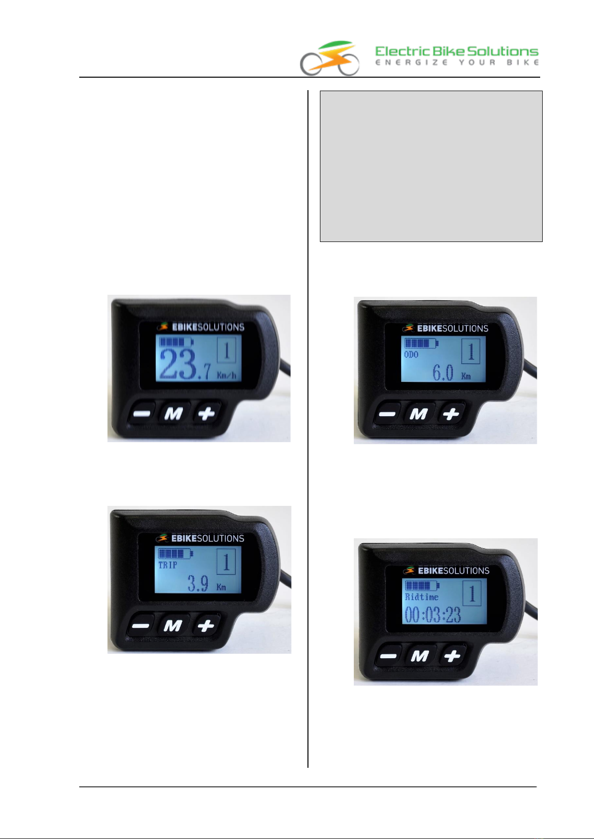
•The display of the current speed is preset. As
soon as you start driving, the display is filled with
the corresponding speed value:
•Press MODE briefly to display the total distance
travelled since the last reset of the short dis-
tance counter "TRIP" instead of the current
speed:
Tips:
- The following applies to all display values of the
infinite loop mentioned in this chapter (➔7.2):
If you do not press MODE again within 5 se-
conds, the display will return to the current
speed.
- "Ridtime", "AVG" and "Max" are reset to "0"
when the display is switched off.
- The short distance counter "TRIP" is not auto-
matically reset to "0". To reset it to "0", proceed
as described in chapter (➔8.1.1).
•Press MODE briefly to display the total distance
travelled since mounting your display "ODO"
instead of "TRIP":
Tip: "ODO" is only displayed when the vehicle is sta-
tionary. As soon as you start driving, "ODO" can no
longer be called up via the MODE button.
•Press MODE briefly to display the total display
switch-on time "Ridtime" since the last time the
display was switched on instead of "ODO":
•Press MODE briefly to display the average speed
"AVG" since the last time the display was swit-
ched on instead of "Ridtime":

Operating instructions
EBS Display Mini - Dot Matrix - V2
Operating Instructions EBS Display Mini - Dot-Matrix - V2, Version V1.0 Copyright © 2018 by Electric Bike Solutions GmbHPage 11
•Press MODE briefly to show the maximum speed
"MAX" instead of "AVG" since the last time the
display was switched on:
•Press MODE briefly to display the current speed
again instead of "MAX".
7.3 Choice of support level
The system comes with 5 "support levels" from
the factory.
The default setting after switching on is level "1".
Here the motor support is at its lowest, provided
you have not overwritten the factory settings. The
higher the level, the more powerful the motor sup-
port.
To select the support levels, proceed as follows:
•If the display is switched off, switch it on (chap-
ter➔7.1).
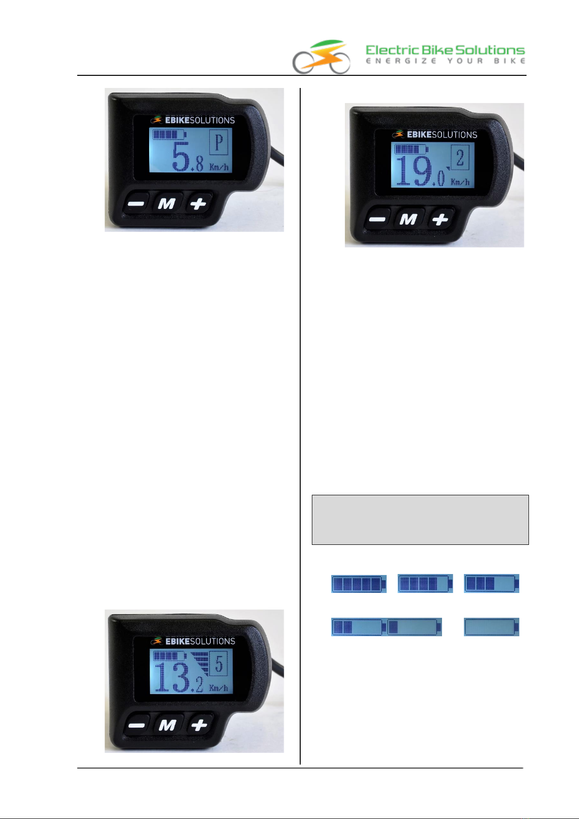
•Briefly press the UP button once to increase the
support level by one at a time. This is shown ac-
cordingly in the display:
•Briefly press the DOWN key to decrease the le-
vel by one at a time:
•At level "0" the motor assistance is switched off.
Nevertheless, the display shows values such as
the current speed at level "0". The pushing aid
can also be activated at level "0".
On longer climbs or steep stretches, you should
ride with at most a medium support level or with
at most medium currents so that the system does
not switch off the motor support too often for ther-
mal reasons.
7.4 6 km/h pushing aid
The display is equipped with a sliding aid.
•If the display is switched off, switch it on (chap-
ter➔7.1).
•Press and hold the DOWN button:
After a good 1 second, the pushing aid is activated.
The bike now accelerates and travels on level
ground at approx. 6 km/h without pedalling as
long as you keep the button pressed. If you re-
lease the DOWN button, the push aid is deacti-
vated.
You can recognise an activated push aid by the
entry "P" in the display:
Operating instructions
EBS Display Mini - Dot Matrix - V2
Operating Instructions EBS Display Mini - Dot-Matrix - V2, Version V1.0 Copyright © 2018 by Electric Bike Solutions GmbHPage 12
Tip: The pushing aid is also active in level 0.
7.5 Dim the display lighting and
switch on again
The display is equipped with a display illumination.
This is always on after the display is switched on.
To dim the display lighting, proceed as follows:
•If the display is switched off, switch it on (chap-
ter➔7.1):
The display illumination is also switched on.
•Press and hold the UP button for a good 1 se-
cond until the display illumination is dimmed.
Tip: You cannot switch off the display illumi-
nation completely; it is only dimmed.
•Press and hold the UP button again for a good 1
second until the display illumination is switched
on again.
7.6 Power display in bar form
The display is equipped with a power indicator in
bar form. The more power the system is currently
"delivering", the more bars you can see in the dis-
play:
•Momentary high performance of the drive:
•Momentary low power of the drive:
7.7 Battery charge indicator
The display is equipped with a battery charge level
indicator (bar graph). This provides you with infor-
mation about the charge status of your drive bat-
tery while you are riding.
•If the display is switched off, switch it on (chap-
ter➔7.1).
•The display shows the battery charge level in six
steps via a battery symbol.
If all bars in the battery symbol are filled, the
battery is (almost) fully charged.
If none of these bars are visible any more and
the frame of the battery symbol in the display is
also flashing, the battery is almost empty and
the motor is switched off. This prevents the bat-
tery from being further discharged and dama-
ged. Recharge the battery as soon as possible.
The bar display varies depending on the load, i.e.
it may display fewer bars under load than at
standstill. This is due to technical reasons and
does not represent a malfunction!
Battery charge indicator:
Full battery => => Battery is getting emptier => => =>
=> => => => => => => Frame flashes,
Battery is almost empty
Operating instructions
EBS Display Mini - Dot Matrix - V2
Operating Instructions EBS Display Mini - Dot-Matrix - V2, Version V1.0 Copyright © 2018 by Electric Bike Solutions GmbHPage 13
8For experienced users: ma-
king individual settings via
the display
The display offers you the possibility to make very
profound changes to the programming of the sys-
tem.
Tried and tested values are stored in the display at
the factory. Adjusting these stored values can have
a negative effect on the behaviour of your conver-
sion kit.
Therefore, please only make changes to the preset va-
lues if you are really sure of the consequences of y-
our actions.
Observe the legal regulations for pedelecs at all
times when making your settings!
Below we list the parameters that you can change
individually if required. The setting options are divi-
ded into 3 categories:
•General settings, the so-called "General Set-
tings" (chapter➔8.1)
You can store your individual settings for the
following parameters in this area:
-1-Clear Trip: Resetting the short trip counter
"TRIP
-2-Set Unit: Distance and speed units
-3-Set WD: Impeller size
-4-Set LS: Maximum speed with motor sup-
port
-5-set voltage: battery status display and low-
voltage cut-off
•Advanced settings, the so-called "Specific Set-
tings" (chapter➔8.2)
You can store your individual settings for the
following parameters in this area:
-1-Power Set: number of support levels and
current level setting per support level
-2-Current Set: Maximum current
-3-Assistant num: Number of magnets in the
PAS disc
-4-Speed Sensor: Number of spoke magnets
-5-Slow Start: Start-up delay
-6-Backlight Set: Backlight
-7-Password Set: Power-on protection pass-
word
•Reset to the display manufacturer's factory set-
tings (chapter➔8.3).
8.1 General Settings, "General Set-
tings
Use the following procedure to access the various
parameters within the "General Settings":
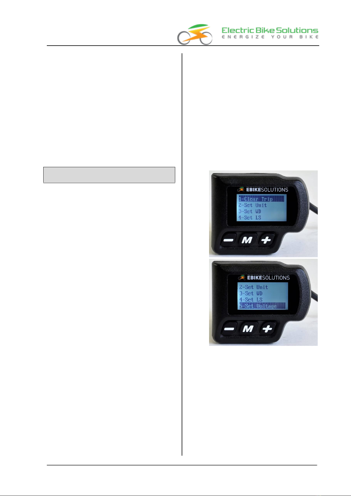
•Switch on the display.
•Press and hold both UP and DOWN buttons for
2 seconds:
The display changes to the "General Settings"
overview:
Tip: You can move from the 1st to the 2nd
image by pressing UP four times.
•Press UP or DOWN to select a parameter in the
list. The currently selected parameter is marked
with a dark bar:
-Press UP to go to a list entry with a higher
number or to move down the list.
-Press DOWN to go to a list entry with a smal-
ler number or to move up in the list.
Operating instructions
EBS Display Mini - Dot Matrix - V2
Operating Instructions EBS Display Mini - Dot-Matrix - V2, Version V1.0 Copyright © 2018 by Electric Bike Solutions GmbHPage 14
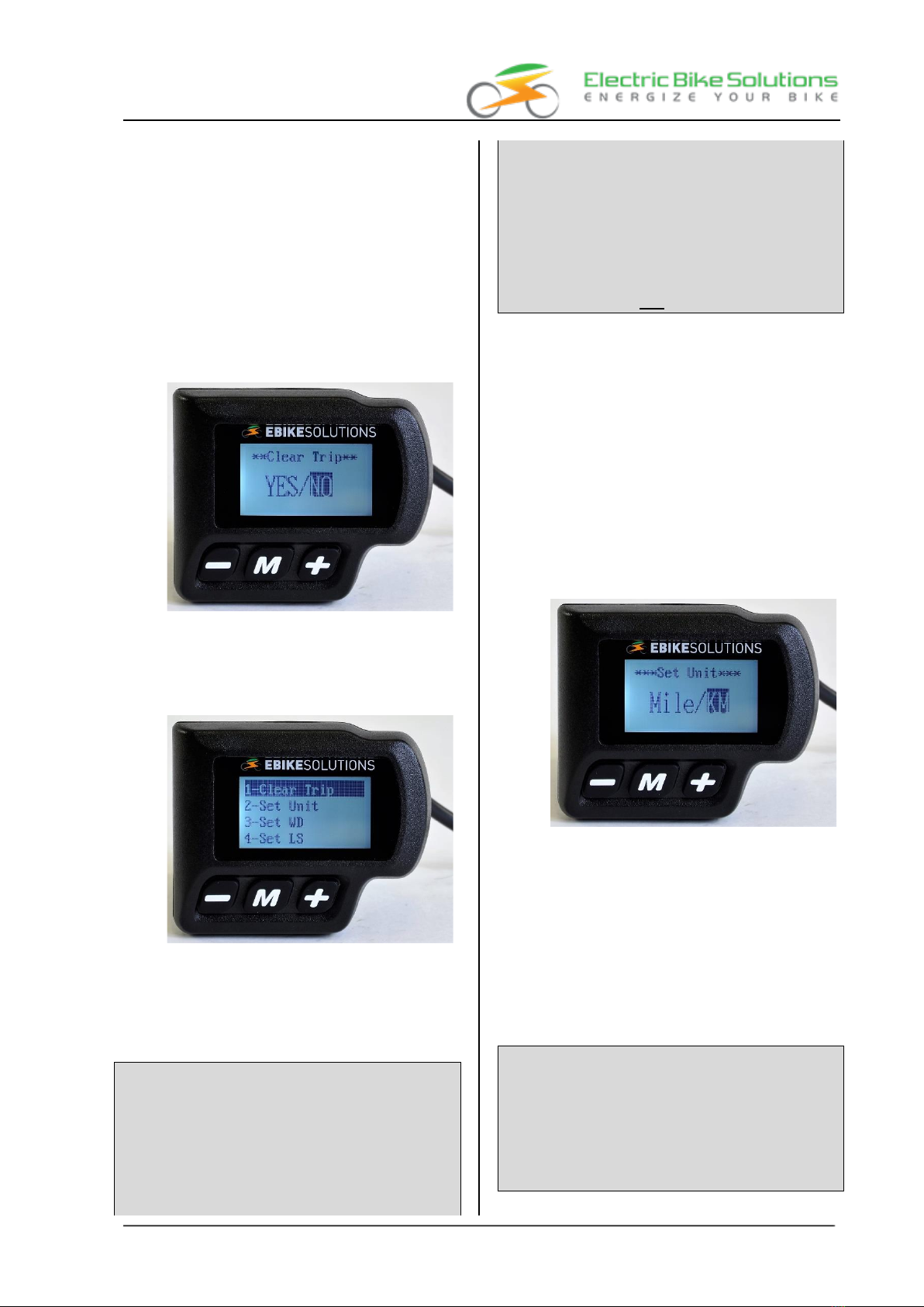
8.1.1 1-Clear Trip: Resetting the short trip
counter "TRIP
With this function you can reset the trip meter /
short distance counter "TRIP" to "0". The short trip
counter counts up the distance travelled until you
manually reset the display to "0":
•Call up "1-Clear Trip" as described in chapter (➔
8.1) and confirm with a short press on MODE.
•Use UP or DOWN to select between "YES" (= re-
set "TRIP") and "NO" (= do not reset "TRIP"):
The factory setting is "NO":
•If you want to reset "TRIP", select "YES" and
briefly press MODE to confirm:
The display briefly shows "OK!" and returns to
the "General Settings" display:
•If you do not want to reset "TRIP", select "NO"
and briefly press MODE to confirm:
The display returns directly to the "General Set-
tings".
Tips:
- If you do not want to change any more parame-
ters within the "General Settings", press and
hold MODE for 2 seconds:
This will exit the current screen, your settings will
be saved. You will be taken directly back to the
display in normal driving mode!
-To exit the settings screen without saving new
data, press and hold the DOWN button for 2
seconds:
You leave the settings screen without saving.
-If you do not press any button within 2 minutes
in this setting mode, the setting mode is
exited:
Your settings will not be saved.
8.1.2 2-Set Unit: Distance and speed units.
speed units
With this function you determine whether "km"
and "Km/h" (metric system) or "Mile" and "MPH"
(British system) are shown for the speed and dis-
tance units in the display:
•Call up "2-Set Unit" as described in chapter (➔
8.1) and confirm by briefly pressing MODE.
•Use UP or DOWN to select between "KM" (=
metric system) and "Mile" (= British system):
The factory setting is "KM":
•If you want to use the British system, select
"Mile" and press MODE briefly to confirm:
The display briefly shows "OK!" and returns to
the "General Settings" display.
•If you want to use the metric system, select
"KM" and briefly press MODE to confirm:
The display briefly shows "OK!" and returns to
the "General Settings" display.
Tip:
- If you do not want to change any more parame-
ters within the "General Settings", press and
hold MODE for 2 seconds:
This will exit the current screen, your settings
will be saved. You return directly to the display
in normal driving mode!
Operating instructions
EBS Display Mini - Dot Matrix - V2
Operating Instructions EBS Display Mini - Dot-Matrix - V2, Version V1.0 Copyright © 2018 by Electric Bike Solutions GmbHPage 15
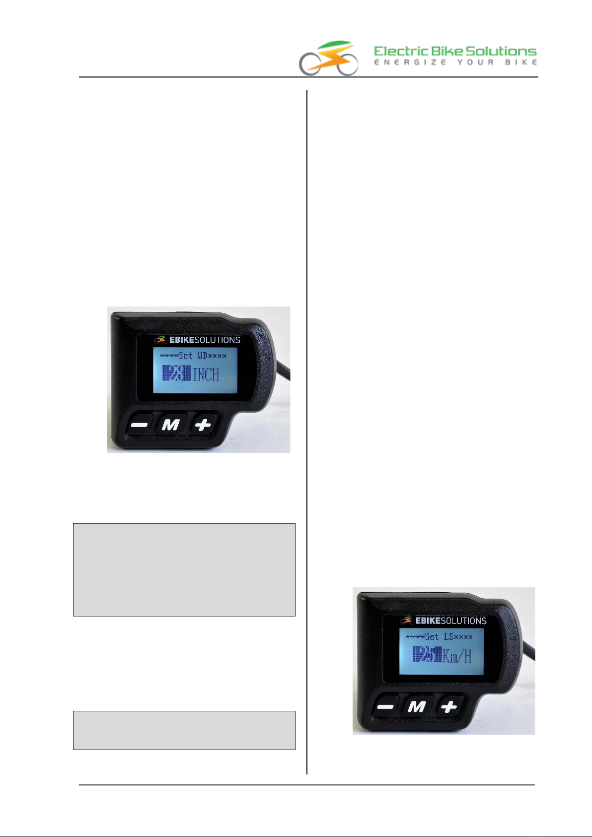
8.1.3 3-Set WD: Impeller size
With this function you store the wheel size of your
bike in the display. This setting is responsible for
the correct display of the speed and distance values
in the display. Various wheel sizes are available for
selection:
•Call up "3-Set WD" as described in chapter (➔
8.1) and confirm by briefly pressing MODE.
•With UP or DOWN you can choose between va-
rious wheel sizes. You can choose from the
following:
08", 09", 10", ..., 26", 700 C, 28", 29", ..., 32".
The value "700 C" is suitable for road bikes.
The factory setting is "28 INCH":
•Once you have selected the wheel size that suits
your bike, briefly press MODE to confirm:
The display briefly shows "OK!" and returns to
the "General Settings" display.
Tip:
- If you do not want to change any more parame-
ters within the "General Settings", press and
hold MODE for 2 seconds:
This will exit the current screen, your settings will
be saved. You will be taken directly back to the
display in normal driving mode!
8.1.4 4-Set LS: Maximum speed with motor
support
With this function you can store the maximum
speed with motor support in the display.
Notes:
-Always observe the regulations of the StVZO or
the legal requirements regarding the maximum
permitted speed in your country!
-The maximum speed with motor assistance is
set to 25 km/h at the factory. In Germany, Aus-
tria and Switzerland, the maximum permitted
speed with motor assistance for pedelecs is 25
km/h. Accordingly, you must set and save the
maximum speed with motor assistance for pe-
delecs via UP or DOWN.
-If you exceed the set maximum speed while dri-
ving, the system switches off the propulsion.
The motor assistance is switched on again as
soon as you drive slower than the set speed.
-If motor assistance is provided at speeds greater
than 25 km/h, your bike is not a pedelec!
-The achievable speed with motor assistance de-
pends in particular on the motor type and the
battery type:
Depending on the motor and battery combina-
tion, there is a maximum technically possible
speed, which can also be above 25 km/h. On
the other hand, a display setting of e.g. 40 km/h
does not mean that the system will also sup-
port up to 40 km/h. This maximum conceivable
speed with motor assistance depends in partic-
ular on the motor and battery combination, and
not (only) on the display setting. This is due to
technical reasons and does not represent a mal-
function!
-Observe the legal requirements for pedelecs at
all times! Set the maximum speed with motor
assistance for pedelecs to 25 km/h!
To set the maximum speed with motor assistance in
the display, proceed as follows:
•Call up "4-Set LS" as described in chapter (➔
8.1) and confirm with MODE.
•Use UP or DOWN to select the speed between
"12 km/h" and "40 km/h":
The factory setting is "25 Km/H":
•Once the desired speed is selected, briefly press
MODE to confirm:

Operating instructions
EBS Display Mini - Dot Matrix - V2
Operating Instructions EBS Display Mini - Dot-Matrix - V2, Version V1.0 Copyright © 2018 by Electric Bike Solutions GmbHPage 16
The display briefly shows "OK!" and returns to
the "General Settings" display.
Tip:
- If you do not want to change any more parame-
ters within the "General Settings", press and
hold MODE for 2 seconds:
This will exit the current screen, your settings
will be saved. You will be taken directly back to
the display in normal driving mode!
8.1.5 5-Set Voltage: Battery status display
and Undervoltage cut-off
With this function you store the voltage thresholds
for the bar display as well as the undervoltage cut-
off:
•Call up "5-Set Voltage" as described in chapter
(➔8.1) and confirm by briefly pressing MODE:
The display changes to "Vol-1", a bar display
with 1 battery segment and a volt number with
a dark background:
•Use UP or DOWN to set the voltage value up to
which 1 battery segment should still be visible in
the display. If the battery voltage falls below the
value listed under "Vol-1", the empty frame of
the battery display flashes in the display and the
motor is switched off.
The display manufacturer's factory setting for
"Vol-1" is "30.0 V". If you reset the display to the
factory settings of the display manufacturer
(chapter (➔8.3)), 30.0 V is stored again:
EBS delivers the display with a "VOL-1" value
equal to "25.0 V". You should also store this va-
lue again after resetting the display to the factory
settings of the display manufacturer:
Once you have selected the appropriate voltage
value (voltage values between 20.0 V and 60.0 V
are possible), briefly press MODE to confirm:
The display changes to "Vol-2", a bar display
with 2 battery segments and a dark volt num-
ber.
•Use UP or DOWN to set the voltage value up to
which 2 battery segments should still be visible
in the display. Briefly press MODE to confirm.
•Proceed in the same way for "Vol-3", "Vol-4"
and "Vol-5":
"Vol-5" corresponds to the battery voltage up to
which all bars are shown in the display.
•If the desired value for "Vol-5" is stored, briefly
press MODE:
The display briefly shows "OK!" and returns to
the "General Settings".
•Press and hold MODE for 2 seconds and you will
return to normal display mode.

Operating instructions
EBS Display Mini - Dot Matrix - V2
Operating Instructions EBS Display Mini - Dot-Matrix - V2, Version V1.0 Copyright © 2018 by Electric Bike Solutions GmbHPage 17
The following table shows the voltage values stored
by the display manufacturer or by EBS for LiIo drive
batteries with 36 V nominal voltage.
Please note that the values stored by EBS are
overwritten after resetting the display to the fac-
tory settings of the display manufacturer (chap-
ter➔8.3) and must then be stored again:
Bar dis-
play
Ref.
Factory
setting
in volts
EBS
setting
in volts
Vol-1
30,0
25,0
Vol-2
33,5
34,1
Vol-3
36,0
35,7
Vol-4
37,4
37,2
Vol-5
39,2
38,8
8.2 Advanced settings, "
Specific Set
Proceed as follows to access the various parame-
ters within the "Specific Settings":
•Switch on the display.
•Press and hold both UP and DOWN buttons for
2 seconds:
The display shows the overview "General Set-
tings":
•Press and hold both UP and DOWN buttons
again for 2 seconds:
The display changes to the "Specific Set" over-
view:
Tip: The above display entries can be called up
by briefly pressing the UP key several times.
•Press UP or DOWN to select a parameter. The cur-
rently selected parameter is marked with a dark
bar:
-Press UP to go to a list entry with a higher
number or to move down the list.
-Press DOWN to go to a list entry with a smal-
ler number or to move up in the list.
8.2.1 1-Power Set: Number of support levels
and and current level setting for each
power per support level
This function allows you to select the number of
support levels of the system.

Operating instructions
EBS Display Mini - Dot Matrix - V2
Operating Instructions EBS Display Mini - Dot-Matrix - V2, Version V1.0 Copyright © 2018 by Electric Bike Solutions GmbHPage 18
The choices are "0-3", "1-3", "0-5", "1-5", "0-7", "1-
7", "0-9", "1-9".
The factory setting is "0-5":
In addition to 3, 5, 7 or 9 support levels, you can se-
lect whether level "0" should also be available or
not. In level "0", data is shown on the display, but
there is no support from the PAS sensor when you
pedal.
Each stage is already preset at the factory with a
certain support value as a percentage of the maxi-
mum current according to chapter (➔8.2.2).
However, you can overwrite this percentage value
for each individual level if necessary.
To set the number of assistance levels and the cur-
rent level setting for each assistance level, proceed
as follows:
•Call up "1-Power Set" as described in chapter
(➔8.2) and confirm by briefly pressing MODE.
•The display entry changes to "***Power Set***"
with a dark background:
The factory setting is "0-5":
•Use UP or DOWN to select the number of sup-
port levels from the above options.
•Once you have selected the appropriate number
of steps (in the example "0-5" was selected),
briefly press MODE to confirm:
For example, the display now shows "5-1- 20%"
with "20%" on a dark background. This means
that stage 1 (of 5 stages) is operated with a pre-
evaluation of 20% of the maximum current:
•Press UP to increase the percentage value (cur-
rent value for level 1), DOWN to decrease it.
Once you have selected the percentage value
that suits you, briefly press MODE to confirm:
The display now shows, for example, "5-2-
40%", with "40%" on a dark background.
•In the same way as described above, enter the de-
sired percentage value for each of the remaining
levels and confirm by briefly pressing MODE.
If a percentage value for the last level is also set,
press and hold the MODE button for 2 seconds:
The display returns to normal display mode.
Excursus: Number of support levels and
-strength and factory settings:
The following table provides information about
the factory settings of the display manufacturer. It
describes the relationship between the number of
support levels and the respective support strength in
the individual stages. The support strength is the per-
centage value of the maximum current:
SCA
/
cur
1
2
3
4
5
6
7
8
9
Steps
0-3 /
1-3
50
74
92
Steps
0-5 /
1-5
20
40
60
80
100
Steps
0-7 /
1-7
40
50
60
70
80
90
96
Steps
0-9 /
1-9
25
34
43
52
61
70
79
88
96
Operating instructions
EBS Display Mini - Dot Matrix - V2
Operating Instructions EBS Display Mini - Dot-Matrix - V2, Version V1.0 Copyright © 2018 by Electric Bike Solutions GmbHPage 19
Their values:
SCA
/
cur
1
2
3
4
5
6
7
8
9
Steps
Tip: If, for example, level 1 already provides too
much support, you can assign a lower percentage
value to this level. This can be useful, for example,
if you are riding in a group in which not all riders
have an electric bike.
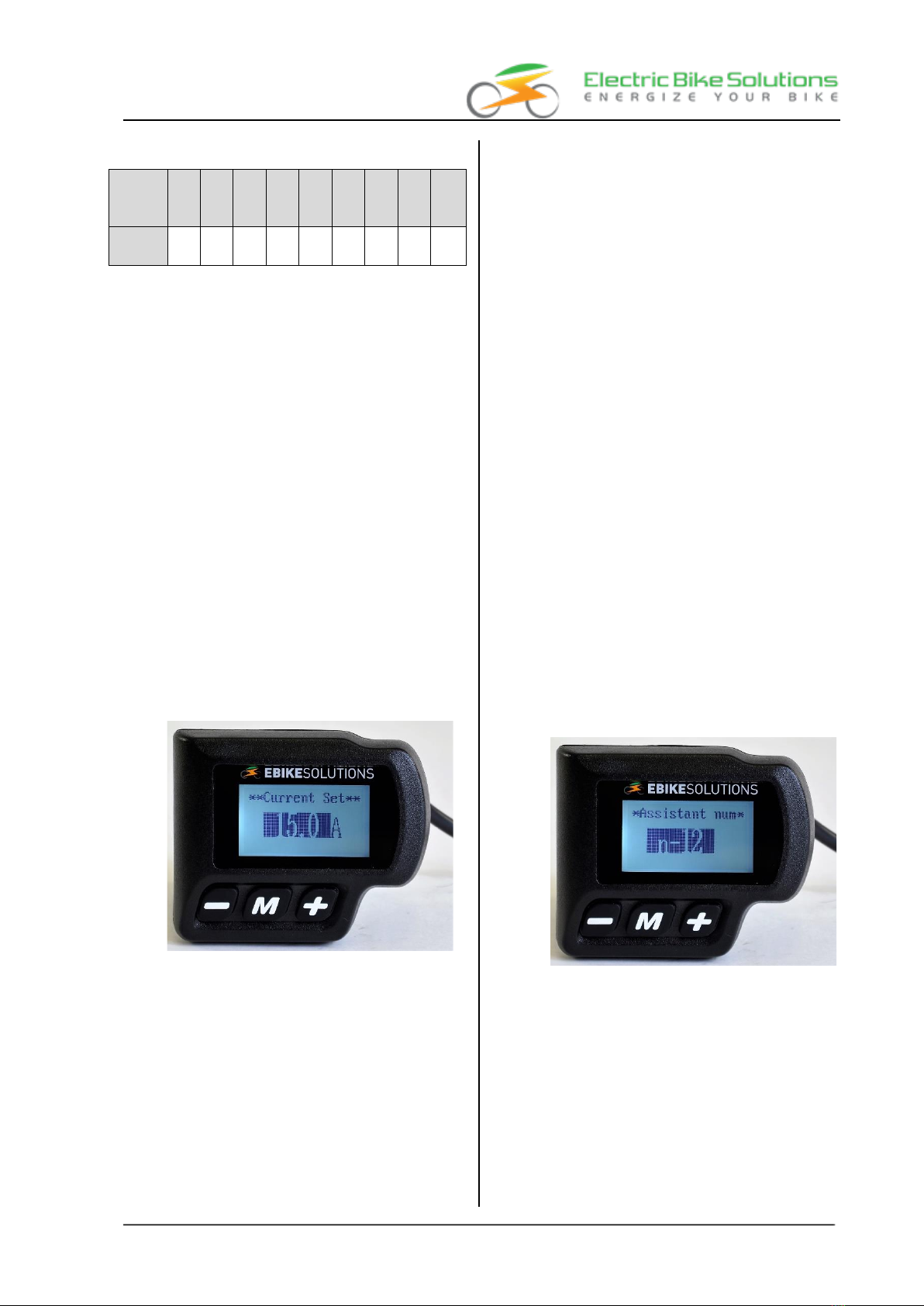
8.2.2 2-Current Set: Maximum current
With this function, you can store the maximum
current with which the system is to be operated.
The set value is the reference point for the percen-
tage settings from chapter (➔8.2.1)).
You can choose between "7.0 A", "7.5 A", "8.0 A",...,
"15.0 A", ..., "22.0 A".
The factory setting is "15.0 A".
Proceed as follows to set the maximum current:
•Call up "2-Current Set" as described in chapter
(➔8.2) and confirm by briefly pressing MODE.
•The display entry changes to "**Current Set**"
with a dark background:
The factory setting is "15.0 A":
•Use UP or DOWN to select the desired maxi-
mum current from the above options.
•Press MODE briefly to confirm:
The display briefly shows "OK!" and then jumps
back to "Specific Set".
Tip: If you do not want to make any more set-
tings afterwards, press and hold MODE for 2 se-
conds:
The display jumps back to the normal display
mode.
Tips:
-Test with lower currents, 13.0 A is also suffi-
cient! This will protect the motor and the bat-
tery, and you will also extend the battery range.
-Although the system switches off the motor
support in the event of overheating, you should
still select a current stage with a maximum of 7
A for longer uphill rides, larger climbs and for
motors with 250 watts rated continuous power
and batteries with 36 V rated voltage.
-Many pedelec batteries are only designed for
maximum currents of 15.0 A.
8.2.3 3-Assistant num: Number of magnets in
the PAS disc
With this function you can store the number of
magnets in the PAS disc.
The choices are "n-05", "n-06, ..., "n-09", "n-12" and
"n-24".
The factory setting is "n-12".
•Call up "3-Assistant num" as described in chap-
ter (➔8.2) and confirm with a short press on
MODE.
•The display entry changes to "*Assistant num*"
with a dark background entry "n-12":
•If the magnetic disc of your EBS conversion
set has 12 magnets, please leave it at the fac-
tory setting "n-12" and do not make any chan-
ges here. Then briefly press MODE to confirm:
The display briefly shows "OK!" and then jumps
back to "Specific Set".
Tip: If you do not want to make any more set-
tings afterwards, press and hold MODE for 2 se-
conds:
The display jumps back to normal display mode.

Operating instructions
EBS Display Mini - Dot Matrix - V2
Operating Instructions EBS Display Mini - Dot-Matrix - V2, Version V1.0 Copyright © 2018 by Electric Bike Solutions GmbHPage 20
In the event that the entry in the display does not
correspond to the magnet number of the PAS disc,
proceed as follows to adjust it:
•Call up "3-Assistant num" as described in chap-
ter (➔8.2) and confirm briefly with MODE.
•The display entry changes to "*Assistant num*"
with a dark background entry:
•Use UP or DOWN to select the desired value
from the above options.
•Press MODE briefly to confirm:
The display briefly shows "OK!" and then jumps
back to "Specific Set".
Tip: If you do not want to make any more set-
tings afterwards, press and hold MODE for 2 se-
conds:
The display jumps back to the normal display
mode.
8.2.4 4-Speed Sensor: Number of spoke-
magnets
This function allows you to store the number of
spoke magnets with which your system is equipped.
The choices are "n-01", "n-02", ..., "n-16".
The factory setting is "n-01".
Tip: For EBS conversion kits with 1 spoke magnet,
leave the setting at "1".
If you do need to make a change, proceed as
follows to make the setting:
•Call up "4-Speed Sensor" as described in chapter
(➔8.2) and confirm with a short press on
MODE.
•The display entry changes to "*Speed Sensor*"
with a dark background:
•Use UP or DOWN to select the desired value
from the above options.
•Press MODE briefly to confirm:
The display briefly shows "OK!" and then jumps
back to "Specific Set".
Tip: If you do not want to make any more set-
tings afterwards, press and hold MODE for 2 se-
conds:
The display jumps back to the normal display
mode.
8.2.5 5-Slow Start: Start-up delay
With this parameter, you can vary within very
narrow limits when the assistance should start after
starting. The higher the value is selected, the later
the system will support you when starting up.
In addition, you determine the time delay with which
the system supports you again after a pedalling
pause and renewed pedalling. The higher the value,
the longer you have to pedal again after a pedalling
break until the system supports you again.
0 sec.", "1 sec.", "2 sec." and "3 sec." are available
for selection.
The factory setting is "0 sec.
Proceed as follows to make the setting:
•Call up "5-Slow Start" as described in chapter (➔
8.2) and confirm with a short press on MODE.
•The display entry changes to "**Slow Start**"
with a dark background:
The factory setting is "0 sec:
This manual suits for next models
1
Table of contents
Popular Bicycle Accessories manuals by other brands


Specialized
Specialized Elite CylcoComputer user manual

Sigma
Sigma BC 16.16 manual

Playcore
Playcore Dero Setbacks installation instructions

VDO Cyclecomputing
VDO Cyclecomputing x3dw instruction manual

Cateye
Cateye RAPID X2 manual

buratti meccanica
buratti meccanica Clorofilla Trail Use and maintenance manual


