Electriq Power PowerPod 2 User manual

1Installation Manual
Installation Manual
for the
PowerPod 2
The Smart Home Battery Solution

2Installation Manual
This installation manual applies to the following PowerPod 2
configurations:
Available PowerPod 2 capacity 10,15, 20 kWh with continuous power
output of 5, 6, 7.6, 8.6, 9.6 kW and cell carrier Verizon, ATT, Rogers, No
Carrier (WiFi Only) options.
PP2 - AC - BAT<Capacity> - INV<Output Power> - CELL<Carrier>
PP2 - DC - BAT<Capacity> - INV<Output Power> - CELL<Carrier>
Model Numbers:
PN: INS-0001_Rev_08_EP_PP2_Manual

3Installation Manual
TABLE OF CONTENTS
Table of Contents
1. Introduction 4
1.1. Whole Home Backup Configuration 5
1.2. Partial-Home Backup Configuration 6
2. Safety Warnings 8
3. Installation and Commissioning 19
3.1. Prerequisites 19
3.1.1. Planning for Installation 19
3.1.2. Tips for Success 20
3.1.3. Commissioning Initial Steps 22
3.2. Mounting System 23
3.2.1. Selecting Mounting Location 26
3.2.2.
Battery Enclosure(s) 28
3.2.3. Inverter Installation 29
3.2.4. Auto-Transformer 31
3.2.5. Automatic Transfer Switch 33
3.3. Installing System 34
3.3.1. General Requirements 34
3.3.2. Conduit 37
3.3.2.1. Conduit and Plugs 37
3.3.3. Battery Installation 38
3.3.4. Auto-Transformer Connections 53
3.3.5. Inverter Connections 55
3.3.5.1. Connect Battery to Inverter 56
3.3.5.2. CTs 57
3.3.5.3. Photovoltaic (PV) (DC-Coupled Only) 60
3.3.5.4. Grid Connections 63
3.3.5.5. Whole Home 65
3.3.5.5.1.
Automatic-Transfer Switch
65
3.3.5.6. Partial-Home (DC-Only) 67
3.3.5.7. PowerHub 2 Connections 71
3.4. Commissioning 74
3.4.1. Turn On System 75
3.4.2. Attach Front Cover 76
3.4.3. Finalize Commissioning 77
3.5. Homeowner Walkthrough 81
4.
User Guide
82
5.
Appendix
89
5.1.
What's in the Box
89
5.2. System Part Numbers 104
5.3.
PowerPod 2 Wiring Diagram with ATS
126
5.4.
Inverter Overload
127
5.5.
Technical Specifications AC-Coupled
128
5.6.
Technical Specifications DC-Coupled
132
5.7.
Grid Parameter Settings
136
5.8.
Decommissioning
137
5.9.
Marks of Conformity
138
5.10.
Warranty
139

4Installation Manual
1. INTRODUCTION
The PowerPod 2 is a high-performance fully integrated home energy
storage, management, and monitoring system powered by LFP (cobalt-
free) batteries. The product includes a hybrid solar/battery inverter
controlled by intelligent software. It comes in both whole home and
partial-home backup. Whole home backup has two options for the
solar connection, 1) the AC option which keeps the solar connected
directly to the load and 2) the DC-coupled option which connects solar
directly to the PowerPod 2 inverter.
All PowerPod 2 models manage grid and backup power from
photovoltaic (PV) panels, batteries, and the utility. When the PV
panels generate enough power, the system will support the backup
load, charge the batteries and feed back to the grid all at the same
time. When the power generated by the PV panels is not sucient
to support the backup load, the inverter takes power from either the
batteries or the utility depending on the mode the homeowner has
selected. For multi-day grid outages the system will resupply power
to the home by restarting from solar each day and solar charge the
batteries even if the batteries were completely drained and system
shut down the previous day. PowerPod 2 comes in dierent inverter,
battery sizes and cellular/WiFi options to match your energy, backup
and data communication needs. There are six inverter models ranging
from 7600 to 9600 W, three batteries sizes; 10, 15 and 20 kWh and four
communication options: Verizon, ATT, Rogers and WiFi.
The PowerTools app is required to commission the PowerPod 2. It is
recommended that the installer have the latest version of the app
installed on their phone before starting the installation process. The
PowerTools App can be downloaded via Google's Play Store or Apple's
App Store.
Introduction
5Installation Manual
+
-
~
RESET
FAULTWi-FiCOMENERGYGRIDBATTERYBACK-UPSYSTEM
DC-Coupled Option
or
AC-Coupled Option
DC-Coupled Option
AC-Coupled Option
Solar Inverter
+
-
Intro / Whole Home Backup Configuration
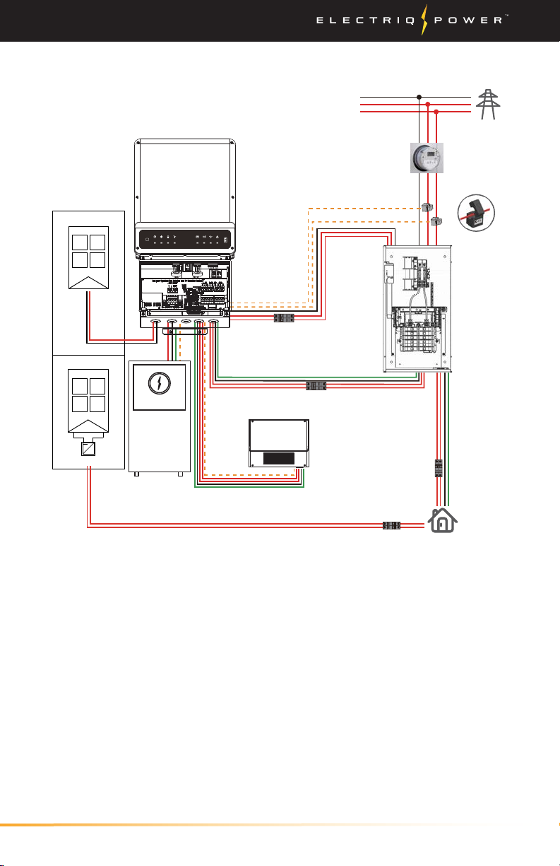
1.1. WHOLE HOME BACKUP CONFIGURATION
BMS
Battery
6Installation Manual
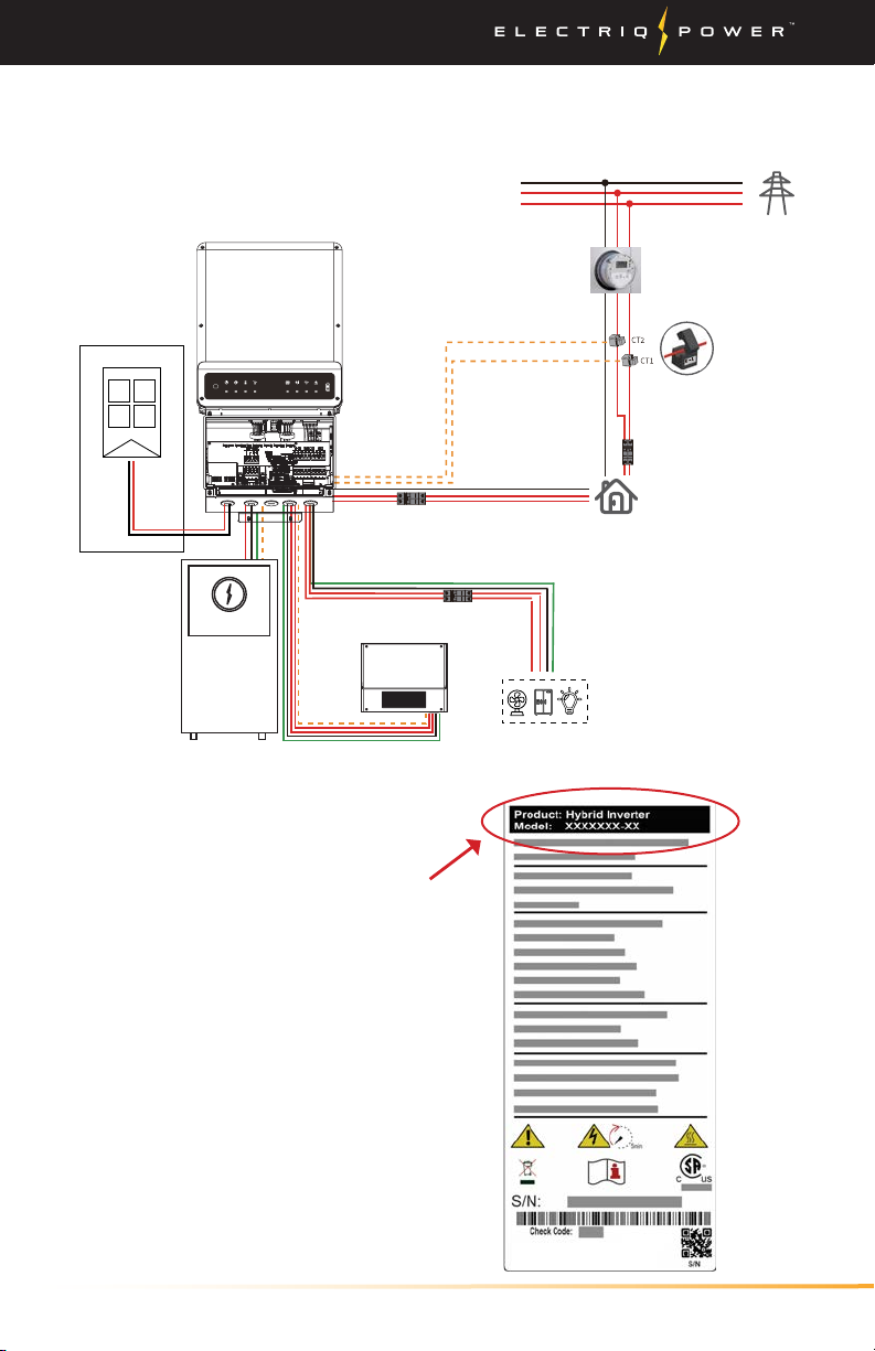
1.2. PARTIAL-HOME BACKUP CONFIGURATION
Intro / Partial-Home Backup Configuration
Inverter Nameplate
Check the inverter nameplate
located on the side of the inverter
labeled 'Model' to determine
which system you have.
DC-coupled is the GWXXXXA-ES
inverter and the AC-Coupled is
the GWXXXXA-BP inverter.
Option only available for DC-coupled systems (inverter model A-ES).
Back-up output breaker
Meter CT Communication
Grid
Power meter
Main Panel
and
Non-backed-up loads
Grid side
Battery
DC Breaker
NTC
BMS
On-grid output breaker
Main breaker
RESET
FAULTWi-FiCOMENERGYGRIDBATTERYBACK-UPSYSTEM
Solar array
DC-Coupled Only
Auto-transformer
+
-
Back-up Partial Load
A-ES
BMS
Battery

7Installation Manual
Intro
Unacceptable Installations
Avoid the following installations which will damage the system or the
Inverter. Following installations should be avoided. Or any damage
caused will not be covered by the Electriq Power warranty policy.
Back-up Back-up
Load
On-grid
Battery
Back-up
Generator
Back-up On-Grid
Single battery bank cannot be connected to multiple
inverters. On-Grid or backup side cannot be connected
to any AC generator.
Backup side cannot be connected to grid.
No parallel connection of the backup is allowed in
general application. Contact Electriq Power first for
advanced application.
Battery without ocial compatible statement cannot
be connected to inverter
8Installation Manual
Safety Warnings
2. SAFETY WARNINGS
READ ALL INSTRUCTIONS AND CAUTIONARY MARKINGS ON THE
UNIT AND THIS MANUAL BEFORE USING THE INVERTER. STORE
MANUAL IN A LOCATION FOR EASE OF FUTURE ACCESS.
WARNING: Users should not attempt to service the PowerPod 2. Only
an authorized PowerPod technician should attempt to service the
PowerPod 2.
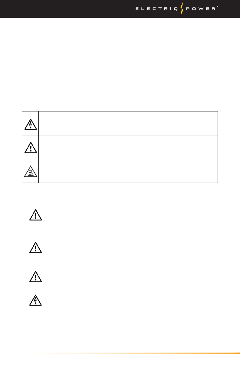
Safety Symbols
WARNING. This indicates the risk of electric shock. The
presence of high voltage levels may constitute a risk of
injury or death to users and/or installers.
CAUTION. This indicates important information where
failure to comply may result in safety hazards or cause
damage to this product.
CAUTION. This indicates the risk of a hot surface. The
surface may reach a temperature high enough to cause
serious burn injuries.
General Precautions
CAUTION. Before installing and using this inverter, read all
instructions and cautionary markings on the inverter and
all appropriate sections of this guide. This inverter must be
installed by licensed electricians only.
CAUTION. Normally grounded conductors may be
ungrounded and energized when a ground fault is
indicated.
CAUTION. Due to inverter weight it is to be lifted by at
least two people for safety.
WARNING. These servicing instructions are for use by
qualified personnel only. To reduce the risk of electric shock,
do not perform any servicing other than that specified in
the operating instructions unless you are qualified to do so.
9Installation Manual
WARNING. Authorized service personnel should
reduce the risk of electrical shock by shutting down the
equipment to install or service.
1. Initiate Solar PV Rapid Shutdown,
2. Turn OFF the Main circuit breakers supplying Grid
connection,
3. Turn OFF the AC Main Backup breakers supplying Load
connections,
4. Turn o the PV Switch located outside the inverter
enclosure on the left side,
5. Remove battery cabinet front panels, 3 mm allen wrench
required,
6. Turn o all DC BMS and battery breakers located on BMS
and each battery. Note, breaker indicator RED is ON and
GREEN is OFF.
7. Allow two minutes for all sources of supply to discharge
and,
8. Check that AC and DC voltages are at a safe level,
9. Access to the inverter wiring requires opening the access
panel, 3 mm allen wrench required,
10. Access to the Auto-Transformer requires opening the
access panel, 2.5 mm allen wrench required.
To isolate equipment, do the following:
1. Turn OFF the Main circuit breakers supplying Grid
connection,
2. Turn OFF the AC Main Backup breakers supplying Load
connections.
WARNING. Do not disassemble this inverter yourself.
It does not contain user-serviceable parts. Attempting
to service this inverter yourself may cause a risk of
electrical shock or fire and will void the warranty from the
manufacturer.
WARNING. To avoid a risk of fire and electric shock, make
sure that existing wiring is in good condition and that the
wire is not undersized. Do not operate the Inverter with
damaged or substandard wiring.
Safety Warnings

10 Installation Manual
CAUTION. Under high temperature environment, the
cover of this inverter could be hot enough to cause burns if
accidentally touched. Ensure that this inverter is away from
normal trac areas.
WARNING. During the installation process, drilling,
punching, and screwing the bolts can cause metal burrs,
which must be cleaned up to prevent them from falling
into the electronics.
WARNING. Use only recommended accessories.
CAUTION. To reduce risk of fire hazard, do not cover or
obstruct the cooling fan.
CAUTION. Do not operate the Inverter if it has received a
sharp blow, been dropped, or otherwise damaged in any
way. If the Inverter is damaged, call for an RMA (Return
Material Authorization).
WARNING.
Exposed hazardous voltage, during servicing
or for emergency procedures use labeled lockout hasps
with durable steel lockout hasps on a lockable manual
breaker or disconnect rated for 240 VAC 50 AAC on the main
service panel to enable Lock-Out-Tag-Out per the Standard
for Electrical Safety in the Workplace, NFPA 70E, and the
Standard for Workplace Electrical Safety, CSA Z462.
CAUTION. Residential indoor installation shall provide
smoke alarms in accordance with building, fire and
installation codes.
Safety Warnings

11Installation Manual
BATTERY PACK WARNINGS:
There is danger of generating heat / smoke / rupture flames.
Do not disassemble battery pack.
Do not touch disassembled battery pack.
Do not reassemble battery pack.
Do not immerse the battery pack in any liquids or get it wet.
Do not short circuit battery pack.
Do not incinerate or heat the battery pack.
Do not use or leave the battery near a fire, stove or heated
place.
Do not impact the battery pack or throw it.
Do not use a damaged and/or deformed battery pack.
Do not drive sharp objects into the battery pack, strike it with
any object or stand on it.
Do not place the battery pack on materials such as tools,
electric wire, screws, etc.
In case of a leak in the battery pack, avoid contact.
Do not touch your eyes if accidental contact with leaky
battery.
Do not expose to corrosive substances such as sea breeze,
steam or chemicals.
Do not install in humid places or places with condensation.
Do not install outdoors in climates where the temperature
drops below 0°C (32°F) for extended periods.
Do not install in direct sunlight.
Do not install or use the PowerPod 2 if it has been damaged
in any way.
The ambient temperature
(charging) must be between 0°C
and 55°C; discharging temperature
must be between -20°C and 55°C;
relative humidity must be between
10% and 90% to ensure optimal
operation. Do not operate where
the temperature and humidity are
beyond the specified limits. High
ambient temperature above 40°C
will cause power derating.
Safety Warnings
SOC Charge/Discharge Rate
>80%
Charge rate will gradually
slow down until SOC
reaches 100%
0% to
100%
Charge rate is derated
when temperature is
below 10° C (i.e. 50° F)
0% to
100%
Charging will stop when
cell temperature goes
below or at 0° C (32° F)
0% to
100%
Discharging will stop when
cell temperature goes
below -20° C (-4° F).
12 Installation Manual
Safety Warnings
WARNING. Only charge the PowerPod 2 within the
specified conditions (e.g. temperature range, voltage,
current, etc. Failure to do so may result in damages, heat
generation, smoke, fire, or explosion.
The unit has a Pollution Degree rating of PD4 (Electrical
equipment for outdoor use). The unit must be mounted
with clearances listed and have adequate air flow. i.e. Must
not be in a closed room smaller than 12' x 12' x 8'.
Do not directly solder the PowerPod 2. This may result in
damages, heat generation, smoke, fire, or explosion.
The unit was designed with an NEMA 3R protection rating
and is for indoor and outdoor installations.
It is recommended that the installation of the enclosures
should be protected from direct sunlight, snow, rain and
other negative influences which may cause function impact
or life aging.
CAUTION. Do not expose the PowerPod 2 to liquids or
flooding.
Do not dispose of equipment or batteries with household
waste.
Do not dispose of batteries in a fire or by burning. The
batteries can explode.
WARNING: Risk of electric shock. Risk of fire. Do not
attempt to repair the battery(ies); it contains no user-
serviceable parts. Tampering with or opening the
battery(ies) will void the warranty.
If the battery(ies) fails, contact Electriq Power Customer
Support for assistance at support@electriqpower.com.
WARNING: Proper disposal of lithium-ion batteries is
required. Follow all local codes and regulations for proper
disposal and recycling of lithium ion batteries.
Contact your Electriq Power representative with any
questions or concerns. The customer cannot keep the old
lithium-ion batteries because they are dangerous and
considered hazardous waste.
WARNING: Take care when lifting the Battery. The Battery
is heavy and may require a lifting tool to initially lift the
battery high enough to get a good hold on it.

13Installation Manual
Safety Warnings
MULTIPLE WARNINGS. NOTE! Method of active anti-
islanding protection: The Inverter monitors for sudden
changes in the impedance of the grid by looking for
changes in the second to the eighth harmonic.
Perform installation and wiring in accordance with all
applicable local electrical codes and standards.
Protection against lightning and resulting voltage surge
must be in accordance with local standards.
Using unapproved attachments or accessories could result in
damage or injury and could result in voiding the warranty.
Use Class 1 wiring methods for field wiring connections
to terminals of a Class 2 circuit. Select the wire size based
on the protection provided by the circuit breakers / fuses.
Install properly rated over current protection as part of the
system installation.
To ensure optimal reliab
i
lity and to meet warranty
requirements, the Inverter must be installed and/or stored
according to the instructions in this guide.
In the event that Inverter, one or more batteries or PowerPod 2 is
defective and needs to be removed, replaced, temporarily uninstalled,
disposed of, decommissioned or if Electriq Power Customer Support
authorizes a replacement (RMA), perform the following steps:
1. Follow installation and service shut down.
2. Contact Electriq Power Customer Support at support@electriqpower.com.
WARNING: Users should not attempt to service the
PowerPod 2.
Only an authorized technician should attempt to service
the PowerPod 2.
WARNING: Risk of injury and equipment damage. Protect
the PowerPod 2 from damage and improper use.
WARNING - ARC FLASH AND SHOCK HAZARD:
Appropriate PPE and Tools Required (protective eyewear
and gloves) while working on the energized equipment.
Voltages up to 600 VDC and 240 VAC Present. Arc Flash
Approach Boundary 1.0 m. Arc Flash Prohibited Approach
Boundary 24 mm.
14 Installation Manual
WARNING: Never touch the terminals of the inverter
directly. It will cause lethal electric shock.
WARNING: The final connection for DC strings should be
done at the array not at the inverter.
WARNING: Because this inverter is non-isolated, only
two types of PV modules are acceptable: monocrystalline
and poly crystalline with only Class A-rated. To avoid
any malfunction, do not connect any PV modules with
possibility of leakage current to the inverter. For example,
non-grounded PV modules will cause leakage current to the
inverter.
CAUTION: To reduce the risk of injury, use the proper cable
size for PV module connection.
CAUTION: To reduce the risk of damage due to surge,
Electriq Power recommends surge protection between the
modules and the inverter.
Note on DC Wiring and NEC
Some electricians or installers may be unfamiliar with DC wiring in a
residential setting. Make note of all relevant codes, which may include:
1. NEC 690.31(G) for DC PV circuits in buildings.
2. NEC 215.12(C)(2) for correct DC wiring coloring.
3. NEC TABLE 310.15(B)(16) for Allowable Ampacities of Insulated
Conductors for Not More Than Three Current- Carrying Conductors in
Raceway (conduit wiring over 12").
4. NEC TABLE 310.15(B)(17) for Allowable Ampacities of Insulated
Conductors in Free Air (chassis wiring).
Rapid Shutdown
Electriq Power Systems are compatible with NEP devices to comply
with NEC 2017, and Tigo rapid shutdown devices to comply with
NEC 2020 regulations. Tigo TS4-A-F and TS4-A-2F are examples of
compatible devices.
Safety Warnings

15Installation Manual
WARNING: To reduce the risk of injury, use the
recommended wire size. It is very important for system
safety and ecient operation to use the appropriate wire
for grid (utility) connection.
WARNING: To prevent the risk of electric shock, make sure
the ground wire is properly earthed before operating this
unit whether the grid is connected or not.
CAUTION: Make sure the AC Load and AC Grid are properly
connected. Misconnecting them will damage the product.
WARNING: Backup load terminals are to be wired to a
separate subpanel. Never connect backup load lines directly
to the main service panel without use of an external
automatic transfer switch. Direct connection of backup
loads output to the grid will result in damage to the
inverter.
WARNING: Make
sure the circuit breaker is o before
making or modifying any connections.
WARNING: Do not connect backup loads output in parallel
with the grid!
CAUTION: Before making the final connection or closing
the breaker, make sure the connections have the correct
polarity. Check polarity labels.
CAUTION: Do NOT apply anti-oxidant substance on the
terminals before terminals are connected tightly.
WARNING: Check positive (+) and the negative (-)
terminals. If the PowerPod 2 is connected with reversed
polarity, unexpected reactions may occur such as damages,
heat generation, smoke, fire, or explosion.
WARNING: Do not connect between the positive (+) and
negative (-) terminals with a conductive material (e.g. wire,
a cable, etc.). This may result in damages, heat generation,
smoke, fire, or explosion.
Safety Warnings
CAUTION: Exceeding the maximum input voltage can
destroy the unit. Check the PV string voltage before wiring
the connection.

16 Installation Manual
Safety Warnings
INVERTER WARNINGS. The Inverter is intended to operate
with an internet connection. Failure to maintain an internet
connection may have an impact on the warranty. See
electriqpower.com/warranty for full terms and services.
Properly mount the Inverter or place it on a flat, plain
surface that can bear heavy weights. Ensure that the
mounting location is structurally suited to bearing the
weight of the Inverter.
During use, storage, and transport, keep the Inverter:
• Properly ventilated
• Away from water, other liquids, heat, sparks, and direct
sunlight
• Away from excessive dust, corrosive and explosive
gases, and oil smoke
• Away from direct exposure to gas exhaust, such as from
motor vehicles
• Free of vibrations
• Away from falling or moving objects, including motor
vehicles
• At an elevation of less than 3,000 m (9,843 ft) above
sea-level
• In a location compliant with fire safety regulations (has
a smoke alarm)
• In a location compliant with local building codes and
standards
• Conditions for the Inverter installation site apply also to
storage conditions.

17Installation Manual
Safety Warnings
IN CASE OF FIRE OR OTHER EMERGENCY
In case of flooding:
• Stay out of water if any part of the system or wiring is submerged.
• If possible, protect the system by finding and stopping the source of
the water, and pumping it away.
• If submerged, the whole system may need to be replaced.
• Let the area dry completely before use.
In case of unusual noise, smell:
• Ensure nothing is in contact with the system or in the venting area
on top of the Inverter or Battery enclosures.
• Ventilate the room.
• Contact Electriq Power Customer Support at:
support@electriqpower.com
In cases of fire or smoke:
• Fire involving Lithium-ion battery can be extremely dangerous.
Lithium-ion batteries can flash fire or explode.
• Close doors as you leave to confine fire as much as possible. If the
alarm is not already sounding, pull the fire alarm on your way out
of the building. If there is no alarm to activate, yell “fire” as you
leave. Move quickly to an open area, away from buildings, trees,
power lines, and roadways.
• When in safe location call fire department and report a possible
Lithium-ion battery fire.
In all other cases:
• If safe to do so,
1. Initiate Rapid Shutdown and allow the DC voltage to drop to
a safe level,
2. Power down inverter, and
3. Disconnect wiring sources of AC and DC power.
• Contact the fire department or other required emergency response
team.
• Evacuate the area.

18 Installation Manual
DISCLAIMER
The AC & DC-coupled systems are transported, used and operated
under environmental and electrical conditions. Any of the following
conditions may void the manufacturer's aftermarket service or
warranty:
• Inverter is damaged during transfer.
• Inverter is out of warranty or any extended warranty if applicable.
• Inverter is installed, refitted or operated in improper ways without
authority from manufacturer.
• Inverter is installed or used under improper environment or
technical condition mentioned in this user manual, without
authority from manufacturer.
• Installation or configuration of the inverter does not follow
requirements mentioned in this user manual.
• The inverter is installed or operated against the requirements or
warnings that are mentioned in this user manual.
• Inverter is broken or damaged by any force majeure like lightening,
earthquake, fire hazard, storm and volcanic eruption etc.
• Inverter is disassembled, changed or updated on software or
hardware without authority from manufacturer.
• Inverter is installed, used or operated against any related items in
international or local policies or regulations.
• Any non-compatible batteries, loads or other devices connected to
the AC or DC-coupled system.
Note: Manufacturer will keep the right to explain all the contents in
this user manual.
For outside installations, ensure that NEMA Type 4X is maintained. All
enclosure connections must be sealed well. Confirm that there is no
risk of water or dust entering the enclosures.
Disclaimer
19Installation Manual
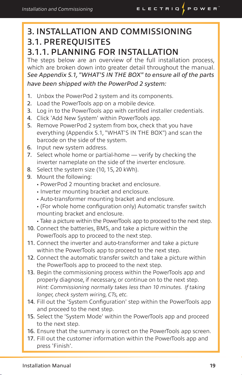
3. INSTALLATION AND COMMISSIONING
3.1. PREREQUISITES
3.1.1. PLANNING FOR INSTALLATION
The steps below are an overview of the full installation process,
which are broken down into greater detail throughout the manual.
See Appendix 5.1, "WHAT'S IN THE BOX" to ensure all of the parts
have been shipped with the PowerPod 2 system:
1. Unbox the PowerPod 2 system and its components.
2. Load the PowerTools app on a mobile device.
3. Log in to the PowerTools app with certified installer credentials.
4. Click 'Add New System' within PowerTools app.
5. Remove PowerPod 2 system from box, check that you have
everything (Appendix 5.1, "WHAT'S IN THE BOX") and scan the
barcode on the side of the system.
6. Input new system address.
7. Select whole home or partial-home — verify by checking the
inverter nameplate on the side of the inverter enclosure.
8. Select the system size (10, 15, 20 kWh).
9. Mount the following:
• PowerPod 2 mounting bracket and enclosure.
• Inverter mounting bracket and enclosure.
• Auto-transformer mounting bracket and enclosure.
• (For whole home configuration only) Automatic transfer switch
mounting bracket and enclosure.
• Take a picture within the PowerTools app to proceed to the next step.
10. Connect the batteries, BMS, and take a picture within the
PowerTools app to proceed to the next step.
11. Connect the inverter and auto-transformer and take a picture
within the PowerTools app to proceed to the next step.
12. Connect the automatic transfer switch and take a picture within
the PowerTools app to proceed to the next step.
13. Begin the commissioning process within the PowerTools app and
properly diagnose, if necessary, or continue on to the next step.
Hint: Commissioning normally takes less than 10 minutes. If taking
longer, check system wiring, CTs, etc.
14. Fill out the 'System Configuration' step within the PowerTools app
and proceed to the next step.
15. Select the 'System Mode' within the PowerTools app and proceed
to the next step.
16. Ensure that the summary is correct on the PowerTools app screen.
17. Fill out the customer information within the PowerTools app and
press 'Finish'.
Installation and Commissioning
20 Installation Manual
Prerequisites / Tips for Success
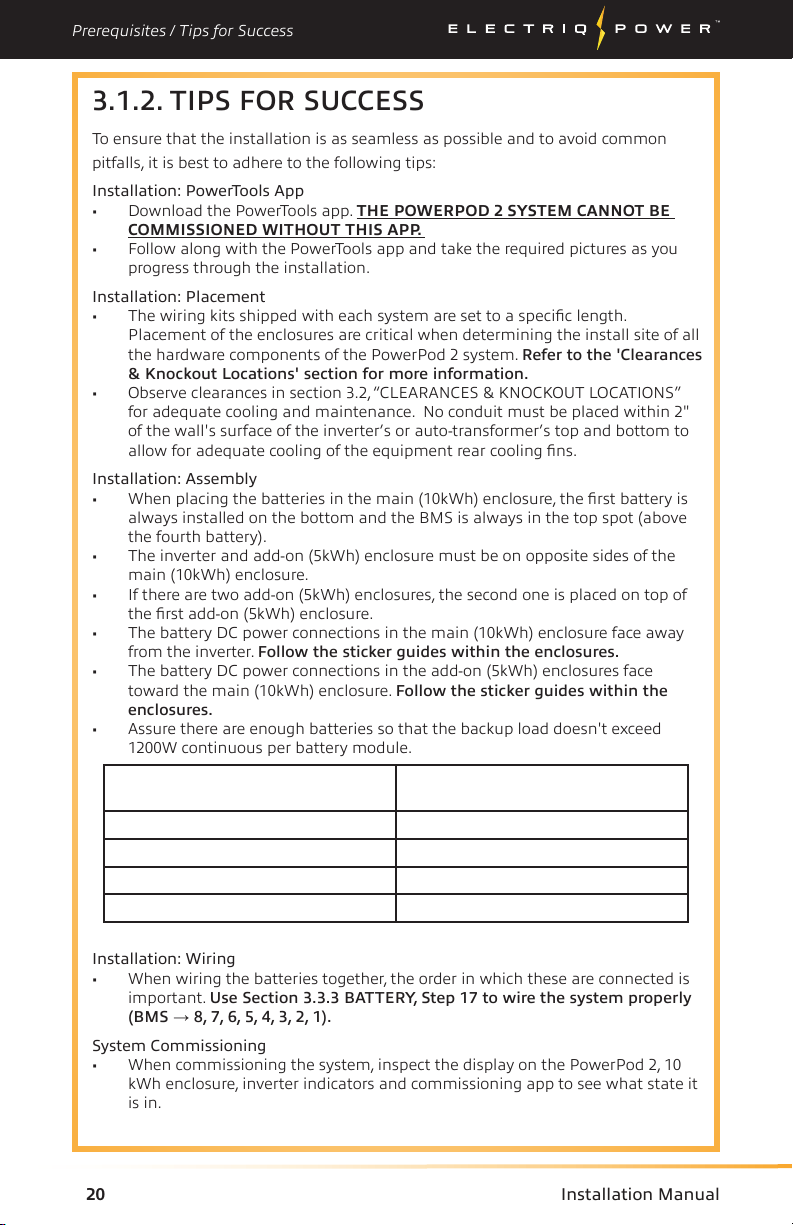
3.1.2. TIPS FOR SUCCESS
To ensure that the installation is as seamless as possible and to avoid common
pitfalls, it is best to adhere to the following tips:
Installation: PowerTools App
• Download the PowerTools app. THE POWERPOD 2 SYSTEM CANNOT BE
COMMISSIONED WITHOUT THIS APP.
• Follow along with the PowerTools app and take the required pictures as you
progress through the installation.
Installation: Placement
• The wiring kits shipped with each system are set to a specific length.
Placement of the enclosures are critical when determining the install site of all
the hardware components of the PowerPod 2 system. Refer to the 'Clearances
& Knockout Locations' section for more information.
• Observe clearances in section 3.2,“CLEARANCES & KNOCKOUT LOCATIONS”
for adequate cooling and maintenance. No conduit must be placed within 2"
of the wall's surface of the inverter’s or auto-transformer’s top and bottom to
allow for adequate cooling of the equipment rear cooling fins.
Installation: Assembly
• When placing the batteries in the main (10kWh) enclosure, the first battery is
always installed on the bottom and the BMS is always in the top spot (above
the fourth battery).
• The inverter and add-on (5kWh) enclosure must be on opposite sides of the
main (10kWh) enclosure.
• If there are two add-on (5kWh) enclosures, the second one is placed on top of
the first add-on (5kWh) enclosure.
• The battery DC power connections in the main (10kWh) enclosure face away
from the inverter. Follow the sticker guides within the enclosures.
• The battery DC power connections in the add-on (5kWh) enclosures face
toward the main (10kWh) enclosure. Follow the sticker guides within the
enclosures.
• Assure there are enough batteries so that the backup load doesn't exceed
1200W continuous per battery module.
Installation: Wiring
• When wiring the batteries together, the order in which these are connected is
important. Use Section 3.3.3 BATTERY, Step 17 to wire the system properly
(BMS →8, 7, 6, 5, 4, 3, 2, 1).
System Commissioning
• When commissioning the system, inspect the display on the PowerPod 2, 10
kWh enclosure, inverter indicators and commissioning app to see what state it
is in.
Battery Size Maximum Continuous Backup load
75% DoD
10 kWh 5000 W
15 kWh 7500 W
20 kWh 7600 (7600 W Inverter)
20 kWh 9600 (9600 W Inverter)
*Max power subject to inverter size. DO NOT EXCEED INVERTER RATING.
Other manuals for PowerPod 2
1
Table of contents
Other Electriq Power Inverter manuals

Popular Inverter manuals by other brands


Growatt
Growatt CP250 installation manual

SolarV
SolarV EPEVER UPower-Hi Series user manual

Mitsubishi Electric
Mitsubishi Electric A800-GN manual

Solar Stik
Solar Stik PRO-VERTER S 3000 Operation and maintenance manual

Generac Power Systems
Generac Power Systems 00941-3 Owners and installation manual

Siemens
Siemens SINAMICS G120P Technical manual