connections 1 (close to CN2 mark) to 6.
In OFF position the contact 3-4 is closed, in ON
position 5-6 is closed, in Dry selection 2-6 is closed.
You have to remove the existing foot-switch and
install a new simple momentary push button and
manage the 3 contacts though 3 relays.
I have used reed relays: small, stable contact and
cheap! In the Fritz schematics I couldn't nd the reed
relay SIP-1A05 so I used the most similar one. In the
pictures attached you'll see that the reed relay has
only 4 pins (instead of the 8 pins in the schematic): the
external ones are the contact, the inner ones the coil.
I've tried the digital switches CD4066 and the TM1134
but the On-resistance and probably the impedance
generate some distortion and "sound leakage" on
Mute position. So I went back on my
electromechanical approach that works noiseless!
A7A7 the pins of the potentiometer MOD (marked VR1
on the PCB) have to be cut (so disconnected from the
PCB) and connected to Nano: the pin on the min. to
the 5V - the pin on the MAX. to GND - the central pin
wiper to analog input A7
OUTPUT
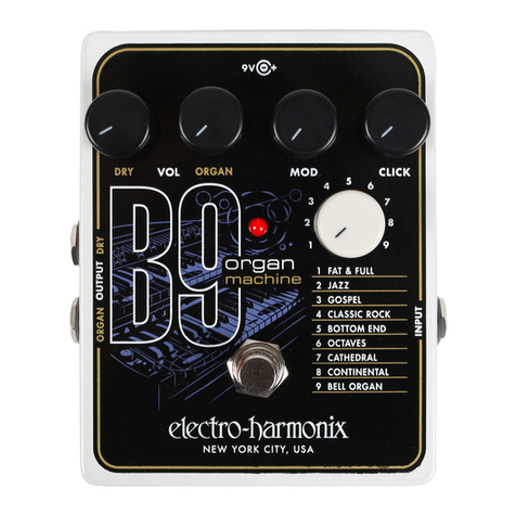
D6D6 contact 3-4 (close is B9 is OFF)
D7D7 contact 2-6 (close is B9 is in Dry mode)
D8D8 contact 3-4 (close is B9 is ON)
D10D10 on the digital potentiometer MCP 42010 to CS
(pin1)*
D11D11 on the digital potentiometer MCP 42010 to S1
(pin3)*
D13D13 on the digital potentiometer MCP 42010 to SCK
(pin2)*
* on the breadboard schematic the digital potentiometer
chip is visualised by a generic 14pins IC with a trimmer
overlapping the pins 8-9-10. This is only a graphic
representation: you don't need anything else than
MCP42010.
A0A0 on the multiplexer 74HC4067 to S3
A1A1 on the multiplexer 74HC4067 to S2
A2A2 on the multiplexer 74HC4067 to S1
A3A3 on the multiplexer 74HC4067 to S0
A4A4 on the OLED display on SDA
A5A5 on the OLED display on SCL
POWER SUPPLY
VINVIN connect the Nano Vin to the +9V on the B9
socket: you can see from the pictures the pin that I
choose but be careful and check with the multimeter
the correct pin!
MULTIPLEXER
In order to double the function of the rotating switch
to select one of the 9 dierent organ eects, I have
used the rotating encoder that can (sort of ) easily
inform Arduino about directions. Then you need to
physically duplicate the existing rotary switch to
inform the B9 of which eect to select. My rst
prototype worked with 10 relays (I have attached a
picture to prove it!). Then I realised that it was a little
too much and, even if I was scared of this mystied
device, I bravely faced the multiplexer world and... I
succeed!
The multiplexer 74HC4067 is capable of 16 positions. I
have used position C0C0 to connect to the common pin
of the rotating switch (you have to cut and isolate the
pin marked "C" from the PCB and connect it to the C0
on the multiplexer): in this way you can "give back' the
control to the rotating switch when needed (...as a
preset!).
The other positions C1.. .C9C1. .. C9 have to be connected to
the 9 pins of the rotating switch: the easiest way is to
use the opposite side of the PCB (I have attached a
picture but, again, pay attention to nd the right
ones!)
I hope that with the help of the breadboard Fritz
schematic and some hints from the pictures, you can
