Electro Industries WarmFlo EM-WC0515H User manual

04/27/2021 HI326
WARMFLO®
COMFORT MODULE
Specific Application
Air exchanger, temperature boost
Make-up air
Temperature comfort boost
Air source HP comfort boost
Comment
This module is a heating element and controller to “temper” the supply air and bring it to a
comfortable level. For general duct temperature boost or heat pump comfort, this unit raises
the warm air supply temperature to the set point temperature value desired. In the make-up
air application the supply or inlet is actually outside air. This unit contains a built-in
controller with duct sensor to modulate the electric element (part of this unit) using only the
required electric energy to reach comfort level. This is more than basic on/off.
This is a single (duct temperature) WarmFlo sensor product. If you need the outdoor sensor
WarmFlo controller, call factory for other models.
MODELS
EM-WC0515H 4,800 WATT AT 240 VOLT, SINGLE PHASE
EM-WC0515L 4,800 WATT AT 240 VOLT, SINGLE PHASE
EM-WC1025H 9,600 WATT AT 240 VOLT, SINGLE PHASE
EM-WC1025L 9,600 WATT AT 240 VOLT, SINGLE PHASE
Drawings: EL907, HH313, HH315, HH321, UAW878, UAW880, XX017

04/27/2021 1 HI326
GENERAL
This is a completely functional electric heat element package with the built-in WarmFlo, duct sensing,
controller. It is installed in the main distribution duct or external to the heat pump unit/air handler.
This module can be installed upflow, downflow, or horizontal. However, it must always be on the
warm air side of the HP coil.
If you desire the outside temperature sensing WarmFlo Smart Controller with its various application
modules (total electric, dual fuel, HP add-on, load management, etc.) this is the wrong product. Call
the factory for further WarmFlo information.
Purpose
When comfort level requires a slight increase in the heat pump air delivery temperature, this module
“tempers” the warm air by raising the warm air temperature a very small number of degrees to produce
comfort level.
Concept (Heat Pump Application)
1. One piece unit, including the electric element.
2. No outdoor sensor.
3. Modulates its own electric element, based upon remote duct sensor and installer set comfort
level temperature.
4. Totally external to the heat pump air handler product.
5. Existing or standard heat pump room thermostat, air handler, strip heat, compressor, etc.; all
remain without modification or functional change.
6. Anyone can install (non HP trade).
7. Adds the comfort level increase in temperature whenever the compressor is on (roomstat
stage 1) and before roomstat stage 2 activates strip heat.
8. Electric element power usage is controlled by duct sensor and comfort level. Electric
element Power is not wasted or turned on in banks.
9. Does not necessarily add to the building service panel loading because as soon as the normal
strip heat turns on (stat stage 2) and raises the temperature, this unit automatically shuts off.
10. Internal logic or chip begins with reset at each “Y” heat call.
ELECTRICAL REQUIREMENTS
EM-WC0515* – 30A Panel Breaker, 20A Nominal Amp
EM-WC1025* – 60A Panel Breaker, 40A Nominal Amp
* H = 10” long element; L = 16” long element
208 Volt application – the elements within the standard product are rated a 240 volts. If operating at
208, there will be approximately 25% reduced capacity. The internal transformer may or may not
adequately operate the control system from a 208 source. Voltage measurements between “R” and
“C” must be 22VAC or greater when the system is in the complete operational mode.

04/27/2021 2 HI326
INSTALLATION REQUIREMENTS
1. All installation work must be performed by trained, qualified contractors or technicians.
Electro Industries, Inc., sponsors installation and service schools to assist the installer.
2. All electrical wiring must be in accordance with national electric codes and local electric
codes, ordinances, and regulations.
3. Observe electric polarity and wiring colors. Failure to observe could cause electric shock
and/or damage to the equipment.
4. This unit can only be used for its intended design as described in this manual. Any internal
wiring changes, modifications to the circuit board, modifications or bypass of any controls, or
installation practices not according to the details of this manual will void the product
warranty, the ARL certification label, and manufacturer product liability. Electro Industries,
Inc., cannot be held responsible for field modifications, incorrect installation, and conditions
which may bypass or compromise the built-in safety features and controls.
HEAT PUMP INSTALLATION – AIR FLOW REQUIREMENTS
Since this is a heat pump application and since this is typically a “temperature boost” electric heating
unit, it is assumed the heat pump air handler capacity is larger than the basic requirement of this
product. But as a verification, the minimum airflow required by this product is:
EM-WC0515* 1000 CFM
EM-WC1025* 1500 CFM
This unit is installed in the warm air, discharge, plenum of the heat pump air handler or in the plenum
above the A-coil (typically two units, one on each side). In all cases it must be external to the heat
pump cabinet. The location within the plenum is determined by the following requirements:
1. Before any horizontal distribution duct, elbows, tee, etc.
2. Maximum practical distance from the HP air handler, but meeting the requirements of paragraph
1 above.
3. If the plenum is a straight discharge (no elbow, obstruction, tee, etc.) from the HP air handler,
National Electric Code paragraph 424-59, four ft. rule, does not apply.
4. If the plenum is larger than 12” x 12” and there is a need to install this unit closer than 18 inches
to the HP air handler discharge blower, call the factory for special baffling instructions.
5. HP air handler discharge blower – attempt to center the electric elements in the plenum and with
the maximum practical distance from the blower discharge.
6. Above A-coil – typically one on each side, angled such that the discharge air from each A-coil
“slab” goes through the element rack. Typically the heat pump airflow is significantly greater
than required by these boost inserts (electric insert is typically small in capacity); therefore,
baffling is not required, simply locate so the majority of the A-coil discharge air goes through
the element rack.

04/27/2021 3 HI326
CLEARANCE – DUCT SURFACE AREAS, DUCT INSTALLATION, ETC.
When installed within air handler plenum or furnace/A-coil plenum, the codes and rules relating to
clearance apply.
When installed in an “inline” duct or round pipe adapter for a general distribution boost heater or air
make-up application, observe the following guidelines:
1. This product must be installed in a metal duct, size of the element rack.
2. There shall be no insulation on the inside of this sheet metal duct section.
3. Any flex-pipe or other insulated pipe must be at least 24” from the electric element.
4. Mounting – there must be at least 2” air clearance around all sides of this sheet metal duct section.
5. If there is a need to insulate this duct section for moisture condensation or in an unheated
compartment, it is permissible to wrap insulation around the exterior of this metal duct section.
6. The control box must be positioned so it will not receive water dripping or collection of moisture.
7. See next section on duct sensor installation.
BOOST HEAT INSTALLATION
This section applies to any warm air duct or inlet/outlet of an air-to-air (HRV) heat exchanger. Also
can be applied for fresh air inlets such as hood vents, small commercial fresh air, make-up air, etc.
Duct size needs to be approximately the size of the electric element rack. If the duct is more than
approximately 2 inches larger for either depth or width, baffling is required. See drawing HH313 for
the single element product or HH315 for the dual element, 10KW product.
1. Air-to-air heat exchanger – install the electric element rack within the discharge duct of the heat
exchanger.
2. Distribution duct, boost heater – install the electric element rack within the air flow duct,
locating a position to cause a majority of the forced air through the electric elements. If the
distribution duct has a depth of 16” or more, we strongly suggest using the “L” model with the 8”
x 16” element rack.
MAKE-UP AIR
Typically in this application outside air enters the inlet and this module gets used to bring up
the mechanical ventilation temperature. You will probably want to use “C” chip, see next
page. Use the following chart to provide additional temperature rise information.
CFM CHART
Temperature Rise Needed 80 70 60 50 40 30
Model Number Watts* CFM CFM CFM CFM CFM CFM
EM-WC0515H 4800 189 216 252 302 378 504
EM-WC0515L 4800 189 216 252 302 378 504
EM-WC1025L 9600 378 432 504 604 756 1007
*At maximum capacity, duct sensor reduces watts as required.

04/27/2021 4 HI326
TEMPERATURE RISE COMMENTS
Typically the maximum temperature rise for this product is 40°F for room air inlet or 20°F for
elevated supply temperature from a typical heat pump.
If it is air make-up, outside air, larger temperature rises are permissible, see table above.
INSTALLATION
1. Locate the appropriate location where this element will temper all the air going to the room
registers or distribution ducting.
2. Cut an 8.5” x 2” slot in the warm air plenum/duct.
3. Control box orientation is not critical.
4. Install duct sensor 2 to 4 air flow feet on the warm side of this module. Select a location where
there is good air mixing.
5. Locate the 24 volt control system “common”. Depending upon heat pump manufacturer, this
could be a “C”, “X” or in some cases “B” screw terminal (probably black or blue wire).
Connect the black (18 gauge) control wire to this common point (this is a “tap” connection).
6. Locate the 1st stage call for heat or compressor turn-on wire. This is typically “Y” terminal
(yellow wire). Connect the yellow wire to this terminal (this is a “tap” connection).
7. From the electrical panel breaker specified above, extend the 240 power to the bottom right
control box compartment and connect as standard 240 volt L1 and L2 power wiring.
8. This power wire must contain a copper safety ground, terminate with green wire.
DUCT SENSOR
This unit is equipped with a remote temperature-sensing probe. This is a solid state probe (actually mini-
micro computer chip at the end of the probe), handle with care.
Suggested installation is in the main warm air stream approximately 20 to 24 airflow inches away from the
electric element. Simply drill a ½” hole in the duct, insert probe, and screw in place.
This duct sensor has a 6-wire cable, coil and tie excess. It should be connected to the Red, ST, and COM
screw terminals. The “OT” screw terminal is not used for this product application.
WARNING
IF THE BLACK AND RED SENSOR WIRES ARE CROSSED OR INCORRECTLY INSTALLED AT
THE TERMINAL BLOCK AND POWER IS TURNED ON, BURNOUT DAMAGE CAN RESULT
WITHIN THE SENSOR PROBE.

04/27/2021 5 HI326
ELECTRICAL HOOKUP
240-volt source – from the model number and nameplate determine KW size and amp draw.
According to local codes, building type, wiring length, etc. use appropriate wiring conductor size and
source circuit breaker. Connect to the pigtail wires or terminal block.
Grounding – route and install appropriate size ground conductor between the ground lug and the
building service panel ground bus. This must be a conductor size according to the total amp rating of
the appropriate unit. Conduit is not an adequate ground conductor.
Operation – this unit “turns on” or heats when 24 volts are applied to the yellow and gray wires. Via
an external 24-volt transformer or an external transformer applying 24 volts through a contact (airflow
switch, thermostat, heat pump “Y” wire, etc.) arrange your control circuit to apply 24VAC power
when you want boost heat.
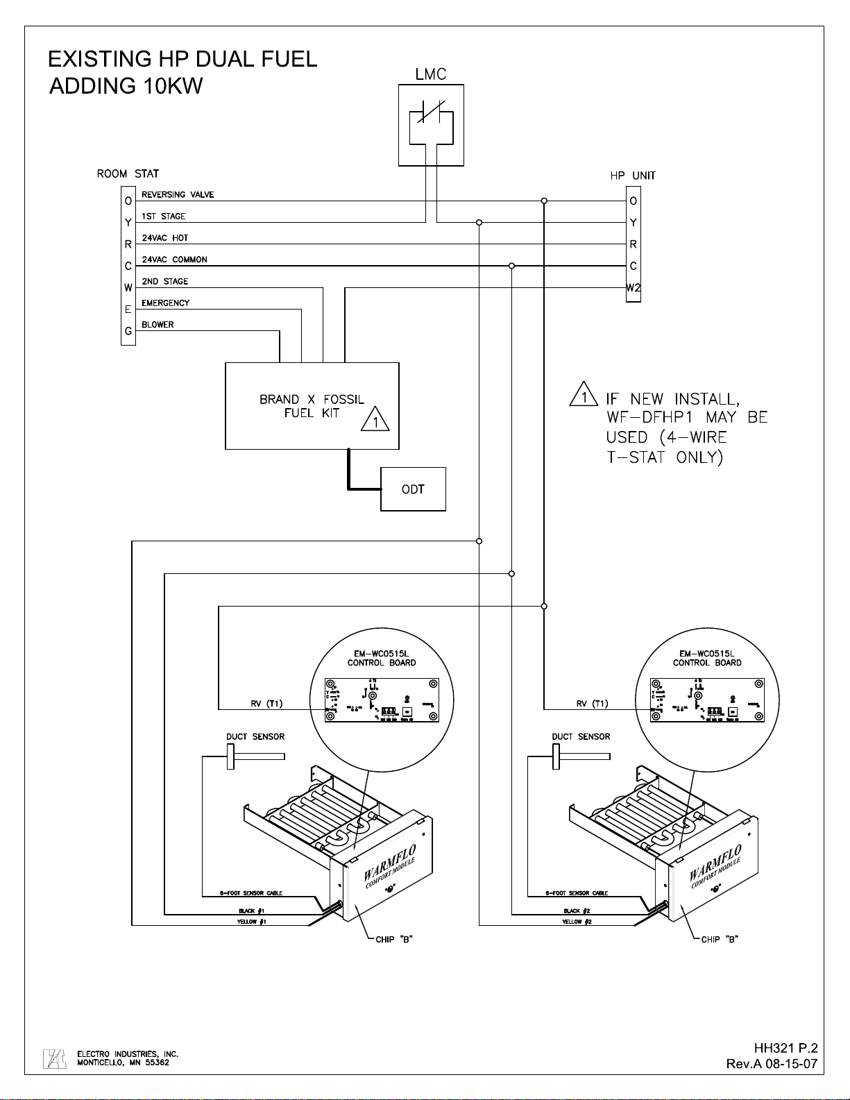
SUMMER OR COOLING DISABLE
This module must be disabled during the cooling cycle to prevent adding heat to the air conditioning
operation.
Select one of the following 3 installation techniques or methods
A. Extend HP reversing valve wire to the designated “RV” tab. When J4 jumper is in place,
a 24VAC input on the RV tab will disable the elements. Review your heat pump’s
installation manual to make certain of your heat pump’s reversing valve logic
B. Add a manual (summer) disable toggle switch between “R” and “RV” tab.
C. Simply turn off 240V breaker during the cooling season.
Method B or C should be used for boost heater applications.
04/27/2021 6 HI326
OPERATIONAL TIPS
Comfort Level Temperature Setting
The inside circuit board contains two screwdriver switches marked 0 through 7. Adjust them to select
the desired set point for your application.
EX: Ideal set point = 86°
Mode Dial would be set to #4
Warm Air Dial would be set to #0
NOTE: MODE DIAL setting # 7 is not applicable to this product
Mode Dial Temperature Range Options
MODEDIAL
WARMAIRDIAL01234567
0‐1014386286110134
MUAII
1‐717416589113137
2‐420446892116140
3‐123477195119140
4226507498122140
55295377101125140
68325680104128140
711355983107131140
Function
1. Electric element power is only used if the heat pump warm air temperature drops below the
above selected setting.
2. Assuming the heat pump warm air temperature is below this setting, the duct sensor sends a
signal to the internal circuit board requesting a boost in warm air temperature.
3. The built-in controller begins pulsing the electric element to add this temperature. The inside
monitor LED indicates the pulsing duration and the electric element is turned on whenever the
LED is on.
4. Except for the LED and/or clamp on amp meter monitor, there are no other indicators or
troubleshooting aids.
5. See previous section titled “Summer or Cooling Disable”.
Option
This unit can be used as a 5Kw duct heater for room stat, second stage operation.
Internal to the circuit board is a “W” terminal. Connecting roomstat second stage heat function to this
“W” terminal causes full electric element turn on (by-pass duct sensor).
Utility Company Load Control Requirement
Arrange wiring so load control receiver interrupts the yellow or “Y” input. If the yellow wire is
connected to the heat pump first stage Y function, the load control receiver is before this yellow wire
connection and the outdoor unit yellow wire.
Checkout and Calibration
There are no field calibration or adjustments.
Total element turn on can be accomplished by jumpering system “R” (24 volts) to “W” internal
terminal. In essence, this bypasses the temperature modulation function and causes the element to be
full on. However, see previous section “Summer or Cooling Disable”.

04/27/2021 7 HI326
MONITOR LIGHTS
The green LED on the circuit board indicates power at the electric element or modulation of the
electric element. In other words, when the LED is on, full power is at the electric element.
Sequence
A. Electric element is on for 10 seconds after the application of 24 volts AC between yellow and black
wire.
B. Electric element turns off if the temperature is above the warm air set point.
C. If the temperature drops, the electric element modulates to bring it back to the desired temperature
level.
D. If the electric element is fully on (LED on constant) this unit cannot make up the air temperature
required between the duct inlet air and the temperature set point at the sensor probe.
TROUBLESHOOTING
A volt/ohm meter is required for proper diagnosing. A clamp-on amp meter is also very helpful.
1. Green LED 1 flashing two pulses every two seconds – indicates control board cannot read
temperature sensor. Verify temperature sensor connections. If secure, replace sensor.
2. No Heat –
Green LED 1 off:
a) Verify temperature set point. If incoming air is higher than set point, element remains off.
Adjust temperature set point to a higher setting and verify element comes on.
b) If incoming air temperature is less than set point, disconnect the red/black/white sensor wires.
1)If unit starts heating and green LED 1 on pulsing, replace temperature sensor
2)If green LED 1 remains off, replace control board
Green LED 1 on:
a) Verify incoming 240 volts power. 24VAC control voltage is typically sourced separately
from the 240 element voltage.
b) Verify 240 volts across element terminals.
1) If 240 volts is present, shut off 240V and disconnect element wires to verify element
resistance. A good element is approximately 10 ohms each.
2) With 240V incoming and if no 240 volts directly across the elements check the
following points referencing UAW890 or UAW892 depending on your model:
a) Measuring across limit switches, 0v (closed) limit is okay. 240V (open) limit is bad
or sensing over 118° or 150°. With power disconnected check ohms when limit is
room temperature. OL means bad limit.
b) Solid state relay (SSR) 4-wire – check for 240VAC across terminals (3, 4) and (1, 2)
1) 240V measured between terminals 3-4 and 0V measured between terminals
1-2 indicate the solid state relay is good.
2) 240V measured between terminals 3-4 and 240V measured between
terminals 1-2 indicate the solid state relay is bad.
c) Mechanical K1 relays:
1) 240V measured across coil and 0V across contacts indicates relay is good.
2) 240V measured across coil and 240 across contacts indicates relay is bad.
d) If there is no control voltage present at SSR or K1 with green LED 1, replace
control board.
3. Not enough heat:
a) Check amp draw. Approximately 10 amps per element means full power output.
b) Verify CFM and temperature rise. High CFM will result in low temperature rise. Cold
incoming air will be warmed based on the CFM Temperature Rise Chart in attached
document EL907.

04/27/2021 EL907
STANDARD EQUIPMENT
▪240V, single phase, external fusing required
▪Quiet DC power relays
▪Thermostat end switch connection point
▪Hi-limits, automatic reset - 150° F/180° fused link
▪Compact enclosure
▪Two element sizes available - 8 x 10 or 8 x 16
▪5-year element warranty
▪2-year parts warranty
TEMPERATURE RISE CHART*
Temperature Rise Needed 80° F 70° F 60° F 50° F 40° F 30° F
Model Watts CFM CFM CFM CFM CFM CFM
EM-WC0515H 4800 198 216 252 302 378 504
EM-WC1025H 9600 378 432 504 604 756 1007
EM-WC0515L 4800 189 216 252 302 378 504
EM-WC1025L 9600 378 432 504 604 756 1007
*Typically the maximum temperature rise for this product is 40° F for room air inlet. If used for make-up air, larger temperature rises are permissible, see table above.
ELECTRIC SUPPLY
Model kW Btu/h Amps Fuse Phase Voltage Source
CB Shipping
Weight Minimum
CFM
EM-WC0515H 4800 16,383 20 N/A 1-60 240 30 7 180
EM-WC1025H 9600 32,765 40 N/A 1-60 240 50 7 370
EM-WC0515L 4800 16,383 20 N/A 1-60 240 30 14 180
EM-WC1025L 9600 32,765 40 N/A 1-60 240 50 14 370
CHIP CODE OPTIONS†
Switch
Position B C D E H
0 96° 20° 40° 60° 88°
1 100° 25° 52° 65° 90°
2 104° 30° 64° 70° 92°
3 108° 35° 76° 75° 94°
4 112° 40° 88° 80° 96°
5 116° 45° 100° 85° 98°
6 120° 50° 112° 90° 100°
7 124° 55° 124° 95° 102°
†Comfort level temperature setting - choose correct chip code for application. Note: Unless otherwise specied, product will be shipped with a default “D” chip.
Specification Sheet - Electric Make-Up Air/Boost Heater
Specications subject to change without notice,
all rights reserved.
▪Temperature sensing with full modulation
▪ Maintainsspecictemperaturesetpoint
▪ Uniquedesignallowsforsimpliedinstallation
▪Cooling mode element disable option
▪Requires 24V external control power supply
▪ARL listed
▪Made in the USA
Monticello, Minnesota
800.922.4138
www.electromn.com

ELECTRO INDUSTRIES, INC.
MONTICELLO, MN 55362
D
E
MODEL DIMENSION
"A" DIMENSION
"B" DIMENSION
"C" DIMENSION
"D" DIMENSION
"E" DIMENSION
"F"
EM-WE1025H 13.38" 10.94" 9.86" 4.91" 2.93" 7.75"
EM-WE1025L 13.38" 10.94" 15.64" 4.91" 2.75" 7.88"
EM-WE1535H 13.38" 10.94" 9.86" 4.91" 4.43" 7.75"
EM-WE1535L 13.38" 10.94" 15.64" 4.91" 4.25" 7.88"
EM-WE2035H 13.38" 10.94" 9.86" 4.91" 5.93" 7.75"
EM-WE2035L 13.38" 10.94" 15.64" 4.91" 5.75" 7.88"
EM-WC0515H 5.16" 9.25" 9.86" 2.07" 1.43" 7.75"
EM-WC0515L 5.16" 9.25" 15.64" 2.07" 1.25" 7.88"
EM-WC1025H 13.38" 10.94" 9.86" 4.91" 2.93" 7.75"
EM-WC1025L 13.38" 10.94" 15.64" 4.91" 2.75" 7.88"
EM-WM1134H 13.38" 10.94" 9.86" 4.91" 4.43" 7.75"
EM-WM1535L 13.38" 10.94" 15.64" 4.91" 4.25" 7.88"
EM-WM1536L 13.38" 10.94" 15.64" 4.91" 4.25" 7.88"
EM-WM2035L 13.38" 10.94" 15.64" 4.91" 5.75" 7.88"
SPECIFICATION DRAWING
CUSTOMER DUCT HEATER
ART-278-00 2.0
1.75 X 1.375
DOUBLE KNOCKOUT
DOUBLE KNOCKOUT
C
.875
1.75
DOUBLE KNOCKOUT
1.375X
1.125 X
F
B
A
.875
DOUBLE KNOCKOUT
X
1.125
DOUBLE KNOCKOUT
.875X
1.125
1.75 X 1.375
DOUBLE KNOCKOUT
Installation Specifications
When installing this duct heater, NEC 424, Part IV, Duct Heaters, applies.
When installed in an “inline” duct or round pipe adapter for a general distribution boost heater or make-up air application, observe
the following guidelines:
1. This product must be installed in a metal duct, size of element rack.
2. There shall be no insulation on the inside of this sheet metal duct section.
3. Anyex-pipeorotherinsulatedpipemustbeatleast24”fromtheelectricelement.
4. Mounting - there must be at least 2” air clearance around all sides of this sheet metal duct section.
5. If there is a need to insulate this duct section for moisture condensation or in an unheated compartment, it is permissible to
wrap insulation around the exterior of this metal duct section.
6. The control box must be positioned so it will not receive dripping water or collection of moisture.


E
M
-
W
C
1025
L
E
M
-
W
C
1025
H
M
O
D
E
L
L
E
N
G
T
H
"
L
"
16
.
00
"
10
.
00
"
D
E
S
CR
I
P
T
I
ON
E
L
E
C
T
R
O
I
N
D
U
S
T
R
I
E
S
,
I
N
C
.
M
ON
T
I
C
E
LL
O
,
M
N
55362
DR
A
W
N
R
E
F
E
R
E
N
C
E
D
O
C
U
M
E
N
T
P
A
R
T
/
A
SS
Y
/
M
O
D
E
L
NU
M
B
E
R
S
C
A
L
E
V
I
E
W
/
DR
A
W
I
N
G
T
Y
P
E
C
H
E
CK
E
D
DR
A
W
I
N
G
S
T
A
T
U
S
D
O
C
U
M
E
N
T
NU
M
B
E
R
S
H
EE
T
D
O
C
U
M
E
N
T
D
A
T
E
A
PPR
O
V
E
D
HH
315
E
M
-
W
C
1025
*
HOO
K
U
P
1
/
1
02
-
01
-
00
N
T
S
R
E
L
E
A
S
E
D
--
M
E
F
W
F
-
C
M
OU
T
L
I
N
E
984
D
I
S
C
O
NN
E
C
T
P
O
W
E
R
BE
F
O
R
E
O
PE
N
I
N
G
C
A
U
T
I
O
N
-
H
I
G
H
V
O
L
T
A
G
E
W
a
r
m
F
l
o
C
o
m
f
o
r
t
M
o
d
u
l
e
ELE
C
T
R
O
I
N
DU
S
T
R
I
E
S
,
I
N
C
.
P
.
O
.
B
OX
538
2150
W
E
S
T
R
I
V
E
R
S
T
R
EET
M
O
N
T
I
C
ELL
O
,
M
N
55362
P
HO
N
E
(
612
)
295
-
4138
4
.
00 10
.
50
13
.
00
"
L
"
2
.
75
1
.
00
9
.
25
6
-
F
OO
T
S
E
N
S
O
R C
A
B
L
E
H
E
A
T
C
A
LL
C
O
MM
ON
B
L
A
CK
Y
E
LL
O
W
D
U
C
T
S
E
N
S
O
R
GR
EE
N
240
V
P
O
W
E
R
L
2
L
1
B
L
A
CK
R
E
D


Page 1 of 2 XX017
Electro Industries, Inc. Residential
Limited Product Warranty
Effective November 1, 2009
Electro Industries, Inc. warrants to the original owner, at the original installation site, for a period of two (2)
years fro date of original purchase, that the product and product parts anufactured by Electro
Industries, Inc. are free fro anufacturing defects in aterials and work anship, when used under
nor al conditions and when such product has not been odified or changed in any anner after leaving
the plant of Electro Industries, Inc. If any product or product parts anufactured by Electro Industries,
Inc. are found to have anufacturing defects in aterials or work anship, such will be repaired or
replaced by Electro Industries, Inc. Electro Industries, Inc., shall have the opportunity to directly, or
through its authorized representative, exa ine and inspect the alleged defective product or product parts.
Electro Industries, Inc. ay request that the aterials be returned to Electro Industries, Inc. at owner’s
expense for factory inspection. The deter ination as to whether product or product parts shall be
repaired, or in the alternative, replaced, shall be ade by Electro Industries, Inc. or its authorized
representative.
Electro Industries, Inc. will cover labor costs according to the Repair / Replace ent Labor Allowance
Schedule for a period of ninety (90) days fro the date of original purchase, to the original owner, at the
original installation site. The Repair / Replace ent Labor Allowance is designed to reduce the cost of
repairs. This Repair / Replace ent Labor Allowance ay not cover the entire labor fee charged by your
dealer / contractor.
WEN Y YEAR (20) LIMI ED WARRAN Y ON BOILER ELEMEN S AND VESSELS
Electro Industries, Inc. warrants that the boiler ele ents and vessels of its products are free fro defects
in aterials and work anship through the twentieth year following date of original purchase. If any boiler
ele ents or vessels are found to have a anufacturing defect in aterials or work anship, Electro
Industries, Inc. will replace the .
WEN Y YEAR (20) LIMI ED WARRAN Y ON SPIN FIN ELEMEN S
Electro Industries, Inc. warrants that the spin fin ele ents of its products are free fro defects in aterials
and work anship through the twentieth year following date of original purchase. If any spin fin ele ents
are found to have a anufacturing defect in aterials or work anship, Electro Industries, Inc. will replace
the .
FIVE YEAR (5) LIMI ED WARRAN Y ON OPEN WIRE ELEMEN S
Electro Industries, Inc. warrants that the open wire ele ents of its products are free fro defects in
aterials and work anship through the fifth year following date of original purchase. If any open wire
ele ents are found to have a anufacturing defect in aterials or work anship, Electro Industries, Inc.
will replace the .

Page 2 of 2 XX017
CONDITIONS AND LIMITATIONS:
1. This warranty is limited to residential, single family dwelling installations only. Any commercial or multi-unit
dwelling installations fall under the Electro Industries Commercial Limited Product Warranty.
2. Electro Industries, Inc. shall not be liable for performance related issues resulting from improper installation,
improper sizing, improper duct or distribution system, or any other installation deficiencies.
3. If at the time of a request for service the original owner cannot provide an original sales receipt or a warranty
card registration then the warranty period for the product will have deemed to begin the date the product is
shipped from the factory and NOT the date of original purchase.
4. The product must have been sold and installed by a licensed electrician, plumbing, or heating contractor.
5. The application and installation of the product must be in compliance with Electro Industries, Inc. specifications,
as stated in the installation and instruction manual, and all state, provincial and federal codes and statutes. If
not, the warranty will be null and void.
6. The purchaser shall have maintained the product in accordance with the manual that accompanies the unit.
Annually, a qualified and licensed contractor must inspect the product to assure it is in proper working condition.
7. All related heating components must be maintained in good operating condition.
8. All lines must be checked to confirm that all condensation drains properly from the unit.
9. Replacement of a product or product part under this limited warranty does not extend the warranty term or
period.
10. Replacement product parts are warranted to be free from defects in material and workmanship for ninety (90)
days from the date of installation. All exclusions, conditions, and limitations expressed in this warranty apply.
11. Before warranty claims will be honored, Electro Industries, Inc. shall have the opportunity to directly, or through
its authorized representative, examine and inspect the alleged defective product or product parts. Remedies
under this warranty are limited to repairing or replacing alleged defective product or product parts. The decision
whether to repair or, in the alternative, replace products or product parts shall be made by Electro Industries, Inc.
or its authorized representative.
THIS WARRANTY DOES NOT COVER:
1. Costs for labor for diagnosis, removal or reinstallation of an alleged defective product or product part,
transportation to Electro Industries, Inc., and any other materials necessary to perform the exchange, except as
stated in this warranty. Replacement material will be invoiced to the distributor in the usual manner and will be
subject to adjustment upon verification of defect.
2. Any product or product part that has been damaged as a result of being improperly serviced or operated,
including, but not limited to, the following: operated during construction phase, with insufficient water or air flow;
allowed to freeze; subjected to flood conditions; subjected to improper voltages or power supplies; operated with
air flow or water conditions and/or fuels or additives which cause unusual deposits or corrosion in or on the
product; chemical or galvanic erosion; improper maintenance or subject to any other abuse or negligence.
3. Any product or product part that has been damaged as a result of natural disasters, including, but not limited to,
lightning, fire, earthquake, hurricanes, tornadoes or floods.
4. Any product or product part that has been damaged as a result of shipment or handling by the freight carrier. It
is the receiver’s responsibility to claim and process freight damage with the carrier.
5. Any product or product part that has been defaced, abused or suffered unusual wear and tear as determined by
Electro Industries, Inc. or its authorized representative.
6. Workmanship of any installer of the product or product part. This warranty does not assume any liability of any
nature for unsatisfactory performance caused by improper installation.
7. Transportation charges for any replacement product, product part or component, service calls, normal
maintenance; replacement of fuses, filters, refrigerant, etc.
THESE WARRANTIES DO NOT EXTEND TO ANYONE EXCEPT THE ORIGINAL PURCHASER AT RETAIL AND ONLY WHEN THE PRODUCT IS
IN THE ORIGINAL INSTALLATION SITE. THE REMEDIES SET FORTH HEREIN ARE EXCLUSIVE.
ALL IMPLIED WARRANTIES, INCLUDING WARRANTIES OF MERCHANTABILITY AND FITNESS FOR A PARTICULAR PURPOSE, ARE
HEREBY DISCLAIMED WITH RESPECT TO ALL PURCHASERS OR OWNERS. ELECTRO INDUSTRIES, INC. IS NOT BOUND BY PROMISES
MADE BY OTHERS BEYOND THE TERMS OF THESE WARRANTIES. FAILURE TO RETURN THE WARRANTY CARD SHALL HAVE NO
EFFECT ON THE DISCLAIMER OF THESE IMPLIED WARRANTIES.
ALL EXPRESS WARRANTIES SHALL BE LIMITED TO THE DURATION OF THIS EXPRESS LIMITED WARRANTIES SET FORTH HEREIN AND
EXCLUDE ANY LIABILITY FOR CONSEQUENTIAL OR INCIDENTAL DAMAGES RESULTING FROM THE BREACH THEREOF. SOME STATES
OR PROVINCES DO NOT ALLOW THE EXCLUSION OR LIMITATION OF INCIDENTAL OR CONSEQUENTIAL DAMAGES, SO THE ABOVE
LIMITATIONS OR EXCLUSIONS MAY NOT APPLY. PRODUCTS OR PARTS OF OTHER MANUFACTURERS ATTACHED ARE SPECIFICALLY
EXCLUDED FROM THE WARRANTY.
THIS WARRANTY GIVES YOU SPECIFIC LEGAL RIGHTS, AND YOU MAY HAVE OTHER RIGHTS WHICH VARY UNDER THE LAWS OF EACH
STATE. IF ANY PROVISION OF THIS WARRANTY IS PROHIBITED OR INVALID UNDER APPLICABLE STATE OR PROVINCIAL LAW, THAT
PROVISION SHALL BE INEFFECTIVE TO THE EXTENT OF THE PROHIBITION OR INVALIDITY WITHOUT INVALIDATING THE REMAINDER OF
THE AFFECTED PROVISION OR THE OTHER PROVISIONS OF THIS WARRANTY.
This manual suits for next models
3
Table of contents
Other Electro Industries Heater manuals

Electro Industries
Electro Industries Make-Up Air II EM-MA01 Installation instructions

Electro Industries
Electro Industries EM-MB01 Installation instructions

Electro Industries
Electro Industries ELECTRO DUCT User manual

Electro Industries
Electro Industries EM-WE1025H User manual

Electro Industries
Electro Industries EM-WX02-240-1-08 User manual

Electro Industries
Electro Industries EM-WX01-120-1-06 User manual


