Electro-Metrics EM-6992 User manual


INSTRUCTION MANUAL
NEAR FIELD PROBE SET
BROADBAND RESPONSE
MODEL EM-6992
ELECTRO-METRICS,
INC.
231
Enterprise Road, Johnstown, New York 12095
Phone: (518) 762-2600 Fax: (518) 762-2812
MANUAL REV. NO: EM6992-3.0 ISSUE DATE:
NOVEMBER
04, 1996

WARRANTY
This Model EM-6992
Near
Field Probe Set
is
warranted
for a
period
of
12 months
(USA only) from
date
of
shipment against
defectivematerials
and
workmanship. This
warranty
is limited to
the
repair
or
replace-
ment
of
defective
parts
and
is void
if
unau-
thorized
repair
or
modification
is
at-
tempted. Repairs for damage due to mis-
use
or
abnormal
operating conditions will
be
performed
at
the
factory
and
will be
billed
at
our
commercial hourly rates.
Our
estimate will be provided before the work
is started.
ELECTRO-METRICS EM-6992
Table
Of
Contents
Section Title Page
1.0 Description 1
2.0 Specifications 2
3.0 Applications 3
4.0 Optional EM-6990
Broadband Amplifier 4
4.1
EM-6990 Description 4
4.2 EM-6990 Specifications 4
4.2.1 Electrical 4
4.2.2 Mechanical 5
4.3 EM-6990 Operating
Instructions 6
4.4 Description EM-6990
Battery Power Supply 6
4.4.1 Charging
The
Battery 7
4.4.2 Replacing The Battery
Cells 8
5.0 Typical Calibration
Chart, H-Field Probes
10
(EM6992-i)

ELECTRO-METRICS
EM-6992
DESCRIPTIONAND USE OF ELECTRO-METRICS
MODEL EM-6992 NEAR FIELD PROBE SET
1.0 Description
The EM-6992 Near Field Probe Set is intended to serve as a
versatile aid for diagnostic testing
of
radiated emissions over
a broad range offrequencies from below 100 kHz to above 1
GHz. The probe setconsists ofthree (3) magnetic field probes,
two (2) electric field probes, 20 cm extension handle, and
custom carrying case. In addition,
an
optional EM-6990 broad-
band pre-amplifier is also available (Refer
to
Paragraph 4.0
for Description/Specifications).
The three magnetic field probes are electrically small (i.e.
resonant frequency above 1GHz) loops
of
varying sensitivi-
ties. The loops are wound within a balanced Faraday shield
that reduces their response to electric fields to a negligible
factor. Each successively largerloop increases sensitivity (in-
dependent offrequency) by approximately
12
to
15
dB. Probes
of reduced sensitivity may be of assistance in isolating an
emission source more precisely.
A ball probe and a stub probe comprise the two electric field
probes. Each probe responds primarily to the electric field
component and rejects the magnetic field component.
Type BNC (female) connectors are used as the output con-
nector on all the probes plus the probe extension handle.
(EM6992-1)
ELECTRO-METRICS EM-6992
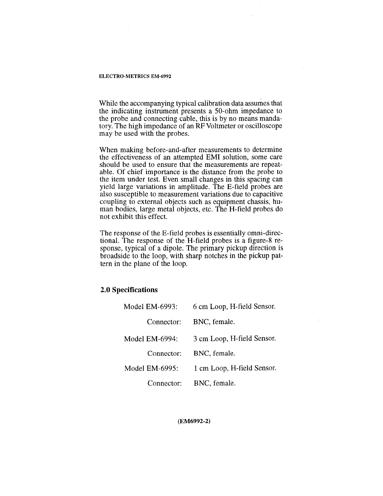
While the accompanying typical calibration data assumes that
the indicating instrument presents a 50-ohm impedance to
the probe and connecting cable, this is by no means manda-
tory. The high impedance ofan RF Voltmeter or oscilloscope
may be used with the probes.
When making before-and-after measurements
to
determine
the effectiveness of an attempted EMI solution, some care
should be used to ensure that the measurements are repeat-
able.
Of
chief importance is the distance from the probe
to
the item under test. Even small changes in this spacing can
yield large variations in amplitude. The E-field probes are
also susceptible to measurement variations due
to
capacitive
coupling to external objects such
as
equipment chassis, hu-
man bodies, large metal objects, etc. The H-field probes
do
not exhibit this effect.
The response
of
the E-field probes
is
essentially omni-direc-
tional. The response of the H-field probes
is
a figure-8 re-
sponse, typical
of
a dipole. The primary pickup direction
is
broadside to the loop, with sharp notches in the pickup pat-
tern in the plane
of
the loop.
2.0 Specifications
Model EM-6993: 6 cm Loop, H-field Sensor.
Connector: BNC, female.
Model EM-6994: 3 cm Loop, H-field Sensor.
Connector: BNC, female.
Model EM-6995: 1 cm Loop, H-field Sensor.
Connector: BNC, female.
(EM6992-2)
ELECTRO-METRICS
EM-6992
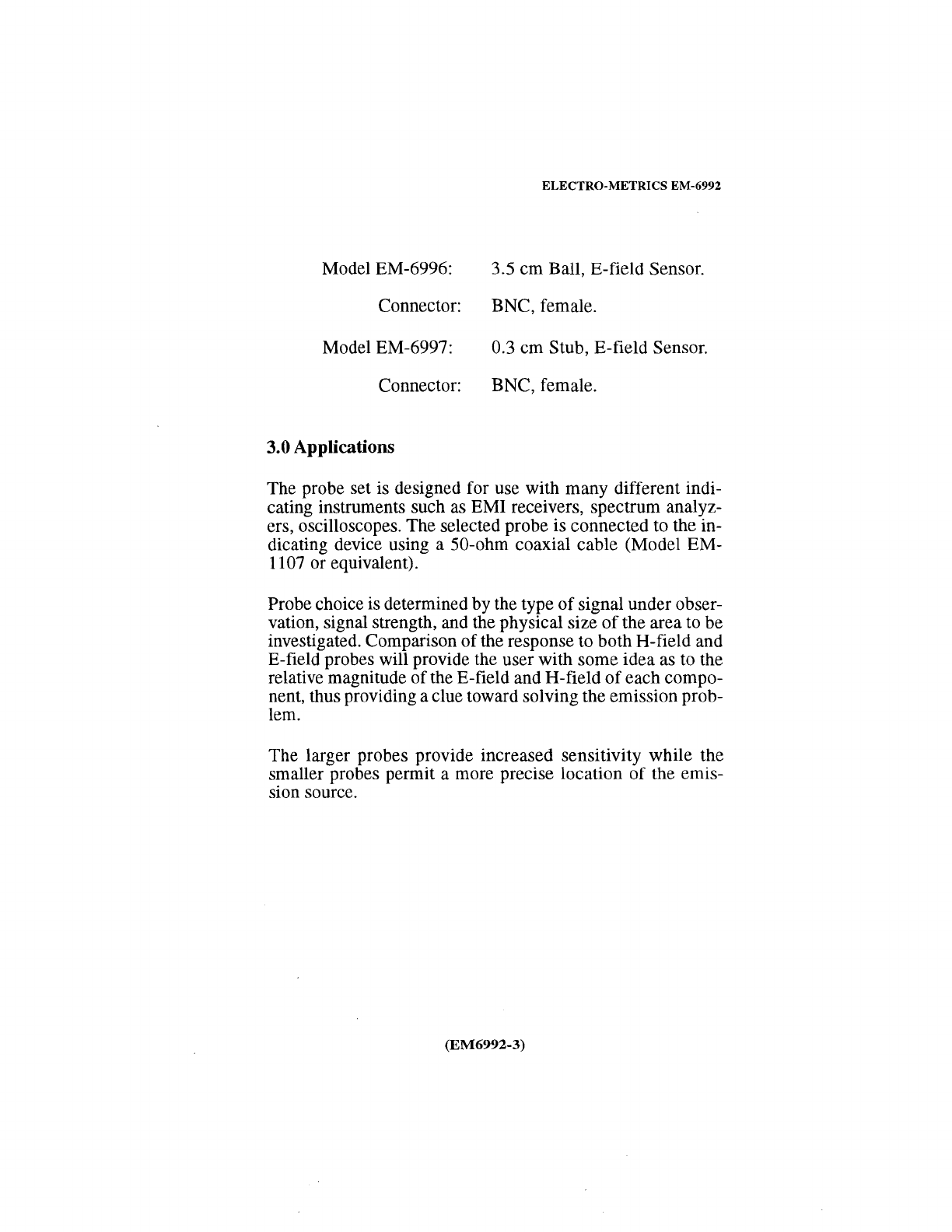
Model EM-6996: 3.5
cm
Ball, E-field Sensor.
Connector: BNC, female.
Model EM-6997: 0.3
cm
Stub, E-field Sensor.
Connector: BNC, female.
3.0 Applications
The probe set is designed for use with many different indi-
cating instruments such as EMI receivers, spectrum analyz-
ers, oscilloscopes. The selected probe is connected to the in-
dicating device using a 50-ohm coaxial cable (Model EM-
1107 or equivalent).
Probe choice is determined by the type
of
signal under obser-
vation, signal strength, and the physical size
of
the area to be
investigated. Comparison
of
the response to both H-field and
E-field probes will provide the user with some idea as to the
relative magnitude ofthe E-field and H-field
of
each compo-
nent, thus providing a clue toward solving the emission prob-
lem.
The larger probes provide increased sensitivity while the
smaller probes permit a more precise location
of
the emis-
sion source.
(EM6992-3)

ELECTRO-METRICS EM-6992
4.0 Optional EM-6990 Broadband Preamplifier
4.1 Description EM-6990
The EM-6990 Broadband Preamplifier
is
designed primarily
for use with the EM-6992 Probe Set in performing EMI di-
agnostic testing. The EM-6990 provides a significant im-
provement in overall measurement sensitivity of the typical
spectrum analyzer. Small size and internal rechargeable bat-
teries make the unit suitable for both bench and field testing.
An external battery charger is used to recharge the internal
batteries.
4.2 EM-6990 Specifications
4.2.1 Electrical
Gain:
25
dB, typical.
Bandwidth(@ -3 dB): 1199.995 MHz.
Frequency Range: 5 kHz-1200 MHz.
Noise Figure: 6
dB.
1
dB
Compression Point:
-1
dBm.
Power Source: 4 rechargeable
"N"
cells.
(1.2 VDC nickel cadmium)
Operating
Time
(approx.): 15 hours between recharging.
Recharge Time: 14-16 hours.
Input/Output Connectors: BNC, female.
(EM6992-4)

Battery Charger:
Charge/Power Jack:
ELECTRO-METRICS
EM-6992
2 Options available:
1) 110
VAC,
50/60
Hz
2) 220
VAC,
50/60
Hz
Size: Inside Diameter:
2.1
mm
Outside Diameter: 5.5 mm.
NOTE
The rechargeable nickel cadmium batteries can
be replaced by 4 commonly available
NON-RE-
CHARGEABLE Alkaline
"N"
cells that increase
the operating time to approximately 100 hours.
Operating Temperature: -20°C to 60°C.
4.2.2 Mechanical
Length: 76
mm
(3")
Width: 89
mm
(3.5")
Height: 44.5
mm
(1.75")
Weight: 230 g (10 ounces)
(EM6992-5)
ELECTRO-METRICS
EM-6992
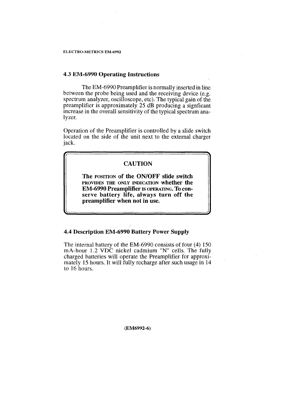
4.3 EM-6990
Operating
Instructions
The EM-6990 Preamplifieris normally inserted in line
between the probe being used and the receiving device (e.g.
spectrum analyzer, oscilloscope, etc). The typical gain
of
the
preamplifier is approximately 25 dB producing a signficant
increase in the overall sensitivity
of
the typical spectrum ana-
lyzer.
Operation
of
the Preamplifier is controlled by a slide switch
located on the side
of
the unit next to the external charger
jack.
CAUTION
The
POSITION
of
the
ON/OFF
slide switch
PROVIDES THE ONLY INDICATION whether the
EM-6990Preamplifier1sOPERATING.
To
con-
serve
battery
life,
always
turn
off
the
preamplifier when
not
in
use.
4.4 Description EM-6990
Battery
Power Supply
The internal battery
of
the EM-6990 consists
of
four (4) 150
mA-hour
1.2
VDC
nickel
cadmium
"N" cells. The fully
charged batteries will operate the Preamplifier for approxi-
mately
15
hours.
It
will fully recharge after such usage in 14
to 16 hours.
(EM6992-6)

ELECTRO-METRICS EM-6992
For longer operating times, the nickel cadmium
"N"
cells
can be replaced by 4 commonly available
NON-RECHARGE-
ABLE Alkaline "N" cells that increase the operating time to
approximately 100 hours.
WARNING
DONOTattemptto RE-CHARGEAL-
KALINE cells. The cells
may
rupture
and cause severe damage
to
the am-
plifier.
4.4.1 Charging The Battery
To
recharge the internal batteries, turn off the EM-6990 and
connect the external batterycharger to the CHARGERJACK
located on the side
of
the unit.
NOTE
To
maximize the recharge rate, the unit should
not be operated while connected to the exter-
nal charger.
In
addition, operation while con-
nected
to
the external charger could cause
ground loops and noise problems.
(EM6992-7)

ELECTRO-METRICS
EM-6992
Two battery charger options are available:
1) 110
VAC,
50/60 Hz
2) 220
VAC,
50/60 Hz
After the batteries have been recharged, remove the external
charger. The unit is now ready for use.
Storage or operation
of
the nickel cadmium battery cells at or
near the upper temperature limit (60°C) will significantly
reduce the number
of
battery charge/discharge cycles.
In addition, operation
of
nickel cadmium battery cells at low
temperatures (<-20°C) will limit their operational life.
4.4.2 Replacing
The
Battery
Cells
To
replace the battery cells:
a. Turn off the EM-6990.
b. Remove the eight(8) screws (#0-80 x 3/16 FLAT HD)
from the edge
of
the top cover.
c.
Carefully remove the old cells from the holders.
d. Replacement cells:
RECHARGEABLE
NICKEL CADMIUM: Panasonic P-15N
Radio Shack 23-121
(EM6992-8)

NON-RECHARGEABLE
ALKALINE:
ELECTRO-METRICS
EM-6992
SPC BRN-N
Radio Shack 23-030
Eveready E90
Ray-0-Vac 81C
Durcell MN 9100
e.
Carefully insert the new cells into the holders, ensur-
ing that the cells are placed with respect to the re-
quired polarity.
f.
Check the inserted cells
to
ensure that no shorting of
the
battery terminals or wiring has occurred.
g.
Replace the top cover and screws carefully. Ensure
that
no
wires are trapped/pinched between the cover
and
case.
(EM6992-9)
ELECTRO-METRICS
EM-6992
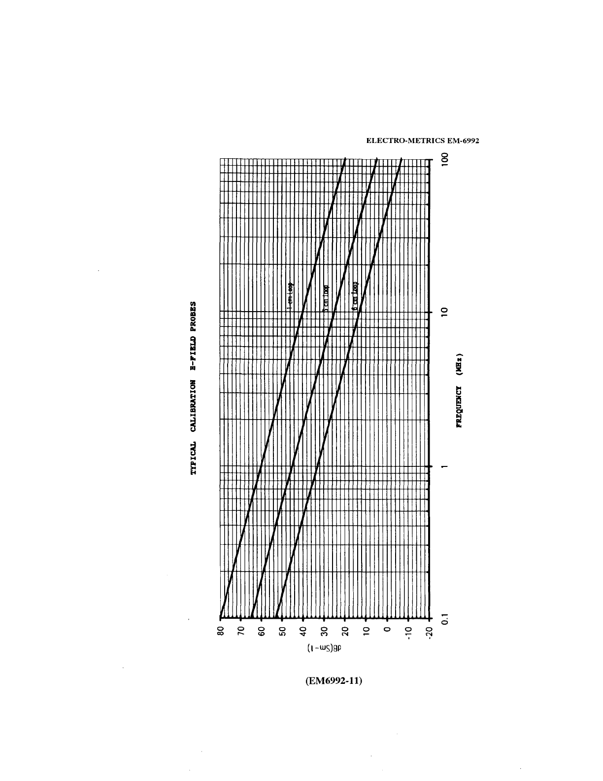
5.0 Typical Calibration Chart H-Field Probes
The calibration chart
of
Page
11
shows typical antenna cali-
bration data for the three (3) H-Field probes supplied with
the EM-6992 Probe Set.
Three typical calibration data plots are shown:
Upper Plot: 1 cm Loop,
Middle Plot: 3 cm Loop,
Lower Plot: 6 cm Loop.
The Y-axis is denoted in dB(Sm-1
).
The X-axis is denoted in Frequency (MHz).
dB(Sm-1)
=dB
above 1 Siemens/meter.
Add dB(Sm-1) to meter reading in dB(µV) to obtain
dB
Si-
emens.
dB(Sm-1) = dB(µA/m).
dB(Sm-1) + 51.5
dB=
dB(µV/m)(Far Field).
dB
Siemens +2
dB
= dB(pT).
dB
Siemens -158
dB
=dB
gauss.
(EM6992-10)
ELECTRO-METRICS
EM-6992
~
~ ~
~
0 0 0 0 0 0 0 0 0 0 0
~ ~
~
~
V M N
~
~
(1-ws)gp
(EM6992-11)
8
0
ci

ELECTRO-METRICS
EM-6992
............
NOTES
..........
..
THIS INSTRUCTION MANUAL
AND
ITS AS-
SOCIATED INFORMATIONIS PROPRIETARY.
UNAUTHORIZED REPRODUCTION
IS
FOR-
BIDDEN.
© 1996 ELECTRO-METRICS, INC.

PRINTED
IN
THE
UNITED
STATES
OF
AMERICA
ELECTRO-METRICS,
Incorporated
231
Enterprise
Road,
Johnstown,
NY 12095
Phone:
(518) 762-2600 Fax: (518) 762-2812
EMAIL:[email protected]
WEB:http://www.electro-metrics.com
Other manuals for EM-6992
1
Table of contents


