Electro Optima Compact Installation instructions

1
Optima Compact
and Titan Optima
Pool Heater
Installation & Operating Manual

1www.elecro.co.uk
Contents
Pages
Optima Compact ..................................... 2-11
Titan Optima ........................................... 12-20
Guarantee Info.............................................. 21
Important Notes!
To ensure that your new heater will give years of trouble free service
please carefully read the following instructions. Incorrect installation
will aect your warranty.
Do not discard this manual, please retain for future reference.
Safety!
The appliance is not to be used by children or persons with reduced
physical , sensory or mental capabilities, or lack of experience and
knowledge, unless they have been given supervision or instruction.
Children should be supervised to ensure they do not play with the
appliance.
Always switch o the power to the Heater before carrying out any
maintenance.
Distributed by:
40 Jabiru Drive
Yeppoon
4703 Queensland
Australia
Tel: +61 749 392 444
Email: sales@spaparts.com.au
Website: www.spaparts.com.au

2
www.elecro.co.uk
Fuse
Electrical
Access
Cover
Status
Indicator
lights
Digital
Control
Thermostat
Flow
Switch
Specication
plate
LH End tting
(Water entry) RH End tting
(Water exit)
Thermal
Cut Out
Manual
Reset Fig 1.
Positioning
Your heater should be horizontally sited allowing sucient space for pipe
connections and wiring.
Optima Compact
Thank you for purchasing the Optima Compact direct electric swimming pool
heater manufactured in England to the highest standards.
Product Overview

3www.elecro.co.uk
Fig 2.
FILTER
PUMP HEATER
POOL
WATER
TREATMENT
NON RETURN
VALVE
Fig 3.

4
www.elecro.co.uk
Pipe Work
It is essential that the pipe work connecting to and from the heater
has a minimum bore (internal diameter) of 1¼” (32mm). To assist correct air
purging and to ensure the heater remains completely full of water during
operation, the return pipe which carries the water back to the pool must
incorporate a safety loop or ‘kick-up’ in the pipe as close as possible to the
heater (see Fig 2).
NOTE: When coupling to a exible pipe a safety loop can simply be created
by routing the pipe up and over an obstacle. Remember to use pipe clips
to securely fasten all hose connections.
Weather Protection
The heater must be installed within a dry weather proof enclosure.
Caution! If the heater is not used during winter months it must be drained to prevent
frost damage.
Electrical Connection
The heater must be installed in accordance with the country / regional
requirements and regulations. In any event the work must be carried out
by a qualied electrician, who will provide a certicate of conformity upon
completion of the work. The power supply must be tted with a RCD.
Cable section: This should be calculated at 5-amp / mm² for distances up
to 20 metres (these sections are indicative and should be checked and
adapted if necessary for cable lengths over 20 metres.
Remove Access Cover
to make the electrical
connections
(Qualied electricians only)
Fig 4.

5www.elecro.co.uk
Power Requirements
All Optima Compact heaters are tted with their own specication plate
that details the power requirements for the heater. Below is a table of power
requirements for standard models - if your voltage is not listed please refer to
the specication plate on the product.
Optima
Compact
Product Code
230V Single Phase 240V Single Phase Optima
Compact Plus
Product Code
kW Load (Amp) kW Load (Amp)
ASP-OC-2 2 9 2 9 ASP-OC-2-T
ASP-OC-3 3 13 3 13 ASP-OC-3-T
ASP-OC-4 4.5 20 5 20 ASP-OC-4-T
ASP-OC-6 6 25 6 25 ASP-OC-6-T
Optima
Compact
Product Code
400V 3 Phase 415V 3 Phase Optima
Compact Plus
Product Code
kW Load (Amp) kW Load (Amp)
ASP-OC-12 12 18 13 18 ASP-OC-12-T
ASP-OC-15 15 22 16.5 22 ASP-OC-15-T
ASP-OC-18 18 26 19.5 26 ASP-OC-18-T
ASP-OC-24 24 35 24 35 ASP-OC-24-T
Flow Requirements
The ow rate of water into the heater must not exceed 283 litres per minute
(17m³/h). A higher ow rate will require the installation of a bypass. The heater
will not operate unless the following minimum ow rates are achieved i.e:
17 litres per minute (1m³/h) for 2 ~ 6-kW heaters and
67 litres per minute (4m³/h) for 12 ~ 24-kW heaters.

6
www.elecro.co.uk
Water exit
Water entry
Fig 6.
Item Description Function
1 ‘P’ button
To display / modify
the required
temperature
2 ‘Down’ button To decrease the
value
3 ‘Up’ button To increase the
value
4 ‘U’ button NOT USED
5
LED-OUT
Continuously
Illuminated
If ashing
Indicates that the
digital thermostat
is calling for heat.
Indicates that the
unit is in
‘Time Delay Mode’
Digital Thermostat Instructions
The digital thermostat displays the temperature in ºC
The digital thermostat tted to your pool heater has been pre-programmed with
all the necessary parameters to ensure reliable service and operation. All you
need to do is set the temperature you would like your water to be maintained at,
this is known as the required temperature.
To display / modify the required temperature, press and release the P button. The
pre-programmed required temperature will be displayed.

7www.elecro.co.uk
Press (3)to increase or (2) to decrease the required temperature.
When the correct required temperature is displayed, press and release the P
button. The unit will then revert to displaying the current water temperature,
but will now control the water temperature, to a maximum of the required
temperature.
Time switching delay:
To prevent overheating of the components within the heater caused by
frequent ’On’ and ’O’ switching (cycling) the digital thermostat has been pre-
programmed with a time delay function. This prevents rapid uctuations in
water temperature from switching the heater ’On’ and ’O’ more than once in a
two minute period. The time delay mode is indicated by the ashing of the Red
indicator (5) on the digital thermostat (see g.6)
Dierential:
When the water has reached the required temperature the heater will switch o
and will not switch back on until the water temperature has dropped by 0.6˚C.
This value is known as the dierential and is in place to prevent overheating to
the switch components caused by cycling.
Water Quality
The water quality MUST be within the following limits:
PH 6.8 - 8.0 TA (Total alkalinity) 80—140ppm (parts per million)
Chloride Content MAX: 150 mg/litre
Free Chlorine: 2.0 mg/litre
Total Bromine: Max 4.5 mg/litre
TDS (Total Dissolved Solids) / Calcium hardness 200— 1,000ppm
Optima Compact heaters are suitable for use with salt water pools with a salt
concentration up to 8000ppm (8g/litre).
For salt water pools with a greater salt content (such as sea water pools) the
Optima Compact Plus heater is required.
Water chemistry is complicated if in doubt seek expert advise.

8
Operating Instructions
The heater will only switch ‘On’ (red heater on light illuminated) when the
following criteria are met i.e.:
• Water circulating pump is ‘On’ delivering in excess of the minimum ow
rate (see ow requirement information - page 5)
• Required temperature is set to a higher value than that of the water (via
the digital thermostat - refer to page 6)
Q: How long will it take to heat my pool?
A: Assuming no heat losses, and a heater sized in the ratio 1.5-kW
per 1,000 UK gallons of water (4,545-litres): it will take 2 days of
continuous running to raise the temperature of a pool from tap
temperature to swimming temperature. Heat loss will slow the heating
process, particularly during periods of cold weather, hence the higher
the water temperature is to be maintained above average ambient air
temperature, the slower the heating process will become.
The only inuencing factors are the level of insulation and the location
of the pool with regard to wind shelter.
Useful advice: To reduce running costs and speed up the heating process; Insulate
the pool wherever possible. A oating solar cover is an essential minimum to retain
heat.
Quick Function Test
Observe the main electricity meter when the heater is on (ie: red heater on light
illuminated) and then observe it again when the heater is in the standby mode
(ie: red heater on light not illuminated) The test should show that the meter is
recording more electricity being used by the heater when the red light is ‘On’. It
is impossible for an electric heater to waste energy, if it is drawing power then
that power will be turned into heat that will be transferred to the water.
www.elecro.co.uk

www.elecro.co.uk
9
Accurate Function Test
If a more accurate test is required to conrm that your heater is delivering the
specied heat output, two electricity meter readings will need to be taken from
the properties main electricity meter, with an exact one hour interval (ie: take
one meter reading and then a second reading exactly one hour later) then by
subtracting the rst reading from the second reading the number of units (kilo
watts / kW) consumed can be calculated. Note that your heater is also rated in
kW hours.
The pool pump and heater will need to be running continuously during the test
(ie: with the heater red light ’On’) To avoid inaccurate results when performing
this test, it is important to refrain from using other high current consuming
appliances in the property (such as tumble dryer, showers, cookers etc). A large
domestic pool pump of 1 horsepower will draw less than 1-kW in a one hour
period. The conclusion of the test should prove that for example a 6-kW heater
and a ½ horsepower pump will draw between 6.3-kW ~ 6.5-kW in one hour. It is
impossible for an electric heater to waste energy, if it is drawing power then that
power will be turned into heat that will be transferred to the water.
Trouble Shooting
HEATER WILL NOT SWITCH TO ‘Heater on’ (RED LIGHT)
In most cases this will be the result of one of the following points not being met:
Possible cause 1: The required water temperature has been achieved.
Remedy: To conrm increase the required temperature by pressing the ‘P’
button to show the current required temperature, then use the arrow keys to
increase the value above the current water temperature, press the P button
again to store the required temperature.
Possible cause 2: The ‘thermal safety cut out’ has tripped.
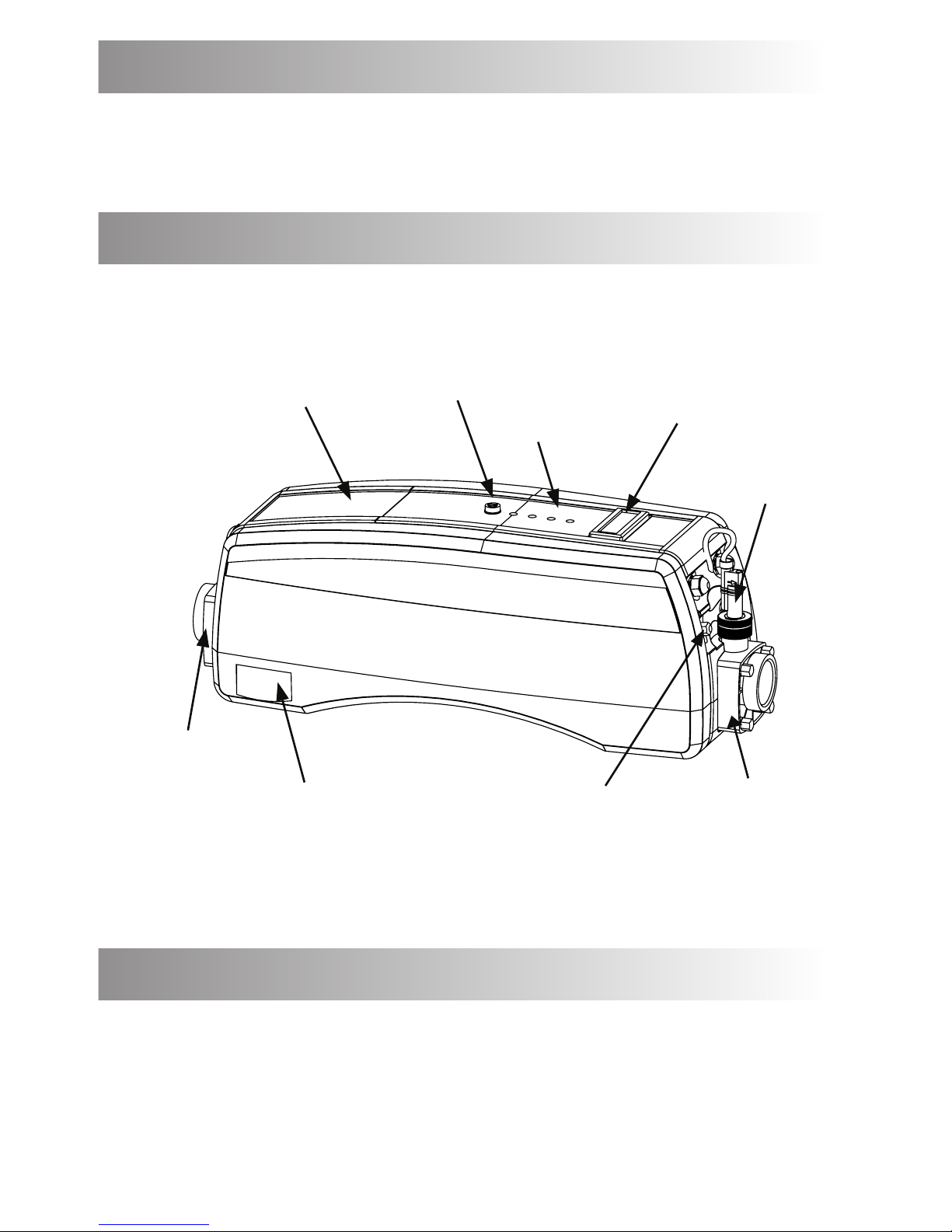
Remedy: Remove the black button cover and press red button to re-set (see g.
7) If a positive click is felt, the cause of the tripping must be investigated and
could be caused by a debris build-up or air pocket trapped inside the ow tube
of the heater.

www.elecro.co.uk
10
www.elecro.co.uk
Possible cause 3: Insucient ow.
If using a cartridge lter: Conrm this by running the system with the
cartridge removed from your pump & lter unit, this will supply the heater with
the maximum ow rate that your unit is capable of. If the heater then switches
’On’ (ie: red light ’On’) a blocked cartridge can be conrmed to be the cause. The
cartridge should be cleaned or replaced.
If using a sand lter: Check the pressure indicator on your sand lter and back
wash if necessary.
NOTE: In some cases the thermal safety cut-out tripping and a low ow
rate can be linked ie: when a lter becomes choked air can be drawn into
the ltration system and become trapped inside the heater so causing the
thermostat to trip.
NO LIGHT APPEARS ON THE HEATER WHEN IT IS SWITCHED ’ON’
Possible cause: Power failure external to the heater
Remedy : Check any fuses, RCD or other switch components installed in the
supply cable. Note: The heater is tted with a 3 Amp glass fuse located on the
top control panel assembly (see Fig 1).
THE WATER ENTERING MY POOL DOES NOT FEEL MUCH WARMER
The temperature gain of the water after it has passed through the heater will be
directly proportional to the volume of water being pumped in
relationship to the power output of the heater.
Fig 7.

www.elecro.co.uk
11 www.elecro.co.uk
For example: A 6-kW heater, when connected to a 4,000 litre / hour pump,
will produce a lift in temperature of approximately 1.2 °C (almost undetectable
to the human hand) however, as the water being heated is re-circulated from
a single body of water, the time required to heat it remains unaected by the
volume of ow. A popular misconception is that slowing down the ow rate will
speed up the heating process.
RoHS Compliance Statement
Elecro Engineering Limited certify that our Electric Swimming Pool Heater
Range complies in accordance with RoHS Directive 2002/95/EC on the restriction
of hazardous substances.
Waste of Electrical / Electronic Equipment
This product complies with EU directive 2002/96/EC
Do Not dispose of this product as unsorted municipal waste.
This symbol on the product or on it’s packaging indicates that this product
should not be treated as household waste. Instead it should be handed over
to the applicable collection point for the recycling of electrical and electronic
equipment.
By ensuring this product is disposed of correctly you will
help prevent potential negative consequences for the
environment and human health, which could otherwise be
caused by inappropriate waste handling of this product.
The recycling of materials will help to conserve natural
resources.
For more information please contact your local Civic oce,
your household waste disposal service or the retailer
where you purchased the product.

www.elecro.co.uk
12
www.elecro.co.uk
Titan Optima
Thank you for purchasing the TITAN OPTIMA direct electric swimming pool
heater manufactured in England to the highest standards.
Product Overview
Fig 1.
Side Panel
R.H.
Chassis Plate
L.H.
Chassis Plate
Top Access
Cover Digital thermostat
temperature controller
Control Panel
Assembly
Flow Switch
R.H.
Manifold Assembly
L.H.
Manifold Assembly
Positioning
Your heater should be horizontally or vertically sited allowing sucient space
for pipe connections and wiring, it should be positioned onto a rm level base
(if oor mounting) or if wall mounting onto a suitable structural wall using the
supplied wall bracket.
Water
exit
Water
entry

www.elecro.co.uk
13
The heater should be installed at a low point in the ltration system.
It should be positioned downstream of (after) the lter and upstream of (before)
any dosing or other water treatment plant. (see g.3)
Fig 2.
Correct
Horizontal oor mounting
In-Correct
Correct Wall
bracket
Flow switch
at top
Wall mounting
For vertical wall
mounting water
must always enter
at the bottom

www.elecro.co.uk
14
Fig 3.
Pipe Work
To assist correct air purging and to ensure the heater remains completely full of
water during operation, the return pipe which carries the water back to the pool
must incorporate a safety loop or ‘kick-up’ in the pipe as close as possible to the
heater (see g. 2 and 3)
The outlet of the electric heater must not be connected to any tap or coupling
other than in accordance with these installation instructions.
Weather Protection
The heater must be installed within a dry weather proof enclosure.
Caution! If the heater is not used during winter months it must be drained to prevent
frost damage.

www.elecro.co.uk
15
Electrical Connection
The heater must be installed in accordance with the country / regional
requirements and regulations. In any event the work must be carried out
by a qualied electrician, who will provide a certicate of conformity upon
completion of the work. The power supply must be tted with a RCD, and a
means of disconnection / isolation.
Remove Access Cover to make the electrical connections
(Qualied electricians only)
SUPPLY
Power Requirements
The table below shows the power requirements and the number of heating
element banks within your heater. Each bank of elements is supplied by two
independent contactors.
Titan Optima
Product Code
400V 3 Phase No. of
element
banks
415V 3 Phase Titan Optima
Plus
Product Code
kW Load
(Amp) kW Load
(Amp)
ASP-TO-18 18 26 2 19 26 ASP-TO-18-T
ASP-TO-24 24 35 2 26 35 ASP-TO-24-T
ASP-TO-30 30 44 2 32.5 44 ASP-TO-30-T
ASP-TO-36 36 52 2 39 52 ASP-TO-36-T
ASP-TO-45 45 66 3 49 66 ASP-TO-45-T
ASP-TO-54 54 78 3 59 82 ASP-TO-54-T
Fig 4.

www.elecro.co.uk
16
Flow Requirements
The heater should be connected to a ltration system with a minimum ow
volume of 200 litres per minute (12m³/h). The maximum ow volume that the
heater will operate with is 750 litres per minute (45m³/h). If the ow volume is
greater, a by-pass must be installed.
N.B the ow direction is xed and must not be reversed.
Digital Thermostat Instructions
The digital thermostat displays the temperature in ºC
The digital thermostat tted to your pool heater has been pre-programmed with
all the necessary parameters to ensure reliable service and operation. All you
need to do is set the temperature you would like your water to be maintained
at, this is known as the required temperature.
To display / modify the required temperature, press and release the P button.
The pre-programmed required temperature will be displayed.
Press (3) to increase or (2) to decrease the required temperature.
Item Description Function
1 ‘P’ button
To display / modify
the required
temperature
2 ‘Down’ button To decrease the
value
3 ‘Up’ button To increase the
value
4 ‘U’ button NOT USED
5
LED-OUT
Continuously
Illuminated
If ashing
Indicates that the
digital thermostat
is calling for heat.
Indicates that the
unit is in
‘Time Delay Mode’
Fig 5.

www.elecro.co.uk
17
When the correct required temperature is displayed, press and release the P
button. The unit will then revert to displaying the current water temperature,
but will now control the water temperature, to a maximum of the required
temperature.
Time switching delay:
To prevent overheating of the components within the heater caused by
frequent ’On’ and ’O’ switching (cycling) the digital thermostat has been pre-
programmed with a time delay function. This prevents rapid uctuations in
water temperature from switching the heater ’On’ and ’O’ more than once in a
two minute period. The time delay mode is indicated by the ashing of the Red
indicator (5) on the digital thermostat (see Fig.5)
Dierential:
When the water has reached the required temperature the heater will switch o
and will not switch back on until the water temperature has dropped by 0.6˚C.
This value is known as the dierential and is in place to prevent overheating to
the switch components caused by cycling.
Water Quality
The water quality MUST be within the following limits:
PH 6.8 - 8.0
TA (Total alkalinity) 80—140ppm (parts per million)
Chloride Content MAX: 150 mg/litre
Free Chlorine: 2.0 mg/litre
Total Bromine: Max 4.5 mg/litre
TDS (Total Dissolved Solids) / Calcium hardness 200— 1,000ppm
Titan Optima heaters are suitable for use with salt water pools with a salt
concentration up to 8000ppm (8g/litre)
For salt water pools with a greater salt content (such as sea water pools) the
Titan Optima Plus heater is required.
Water chemistry is complicated if in doubt seek expert advise.
Operating Your Heater
Upon completion of the installation, the water-circulating pump should be
run to purge the system and the heater of air (i.e. remove any trapped air in
the system and heater). On initial power up of the heater the clear POWER
neon indicator should illuminate and will remain illuminated as long as the

www.elecro.co.uk
18
power supply to the heater is switched on. The heater will only switch ‘ON’ (red
light indicator illuminated) when the following criteria are met ie:
• Water circulating pump is ‘On’ delivering in excess of the minimum ow
rate of water (see ow requirement information - page 16)
• Water temperature set point (required temperature) is set to a higher
value than that of the water (via the digital thermostat - refer to page 16)
If after initial power up either the Clear NO / LOW FLOW or Amber OVER TEMP. TRIP
neon indicators are illuminated please proceed to the troubleshooting section.
Select your required temperature (described earlier in this booklet). The
contactors will now click in and the cascade time delay function will begin. In
5-seconds time the rst bank of elements will be switched on together with
the red HEATER ON neon indicator. Following a further 5-second time delay the
second bank of elements will be switched ‘ON’. Following a further 5-second
delay the third bank of elements will be switched ‘ON’. This sequence of staged
energisation (timed energisation) will continue depending on the power output
of your heater (see table).
N.B - The number of banks your Titan Optima heater has depends on the power
output of the heater, please refer to the power requirement section earlier in
this manual to check the number of element banks within your heater.
www.elecro.co.ukwww.elecro.co.uk
No. of
Element
banks
Delay to
full power
(secs)
215
320
From Initial
Power On:
Digital thermostat
temperature controller
Fuse
Over
Temperature
Trip
No / Low
Flow
Heater
‘ON’
Power
Control Panel
Assembly:
Fig 6.

www.elecro.co.uk
19
Trouble Shooting
THE CLEAR NO / LOW FLOW NEON INDICATOR IS ILLUMINATED:
Possible Cause A: The ow volume through the heater has fallen below 200-litres
per minute (12m³/h) or has stopped completely.
Solution: Increase the volume of ow through the heater, check for blockages
or if the lter(s) require backwashing.
Possible Cause B: The heater has been plumbed incorrectly
Solution: The TITAN heater has a xed ow direction indicated on the manifold
that houses the ow switch, ensure that the water has been plumbed in the
correct direction through the heater.
THE AMBER OVER TEMP. TRIP NEON INDICATOR IS ILLUMINATED:
Possible Cause: The ‘thermal safety cut-out’ has tripped.
Solution: Unscrew the black cover on the water exit side of the heater, press
the red button, if a positive click is felt it is likely that an air pocket has built up
within the heater and needs to be purged to prevent damage to the heating
elements (see diagram below).
IF A POSITIVE CLICK IS NOT FELT:
Cause: The air temperature within the control enclosure is above 60˚C to reduce the
temperature run the circulation pump for 5 minutes to act as a heat sink to cool the
enclosure - the electrical cabinet thermal cut-out will automatically reset itself when
it has cooled to a safe operating temperature.
N.B -The Amber OVER TEMP. TRIP neon indicator will only ever illuminate when
the required temperature is above the current water temperature
Fig 7.
The Amber OVER TEMP. TRIP
neon indicator only illuminates
when the required temperature
is above the current water
temperature.
This manual suits for next models
1
Other Electro Swimming Pool Heater manuals
Popular Swimming Pool Heater manuals by other brands

Hayward
Hayward H100ID1 Installation & operation manual

Baxi
Baxi Bermuda SL3 Installation and servicing instrucnions

Laars
Laars Pennant PNCP 500 Installation and operation instructions

Jandy
Jandy Legacy LRZM Installation and operation manual

Raypak
Raypak HIDELTA 992B Specification sheet

Pahlen
Pahlen MidiHeat EHD manual