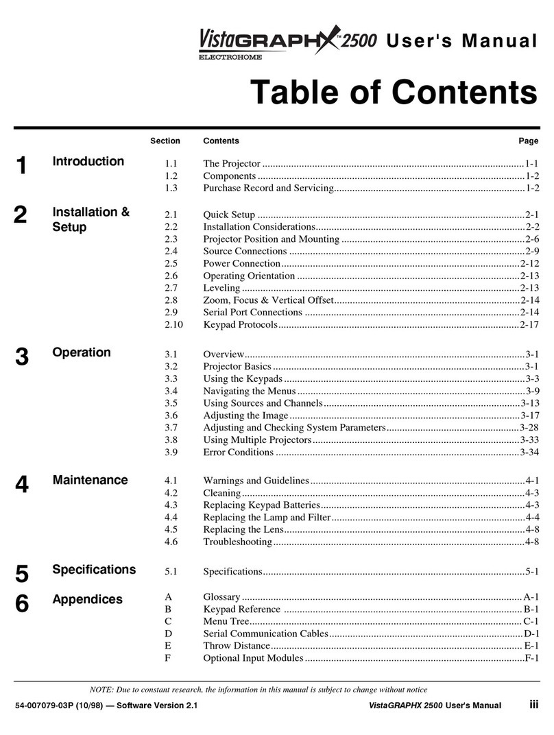
Electrohome ECP 4100 Series User manual

ECP41OO
SERIESPROJECTION
SYSTEM
SERVICE
MANUAL
DUE
TO
CONSTANTRESEARCH,THE INFORMATION
INTHISMANUAL
IS
SUBJECTTOCHANGE
WITHOUTNOTICE.
ECP
is
a registered
trademark
of Electrohome
Limited.
g Copyright1990by ElectrohomeLimited.
All rights raservad. Printedin Canada/54-7904-03P
(06/90)

WARNING
THE
ECP41OOSERIES
PROJECTORGENEMTES
ANDMAYMDIATE
MOIO FREQUENCY
ENERGY.
IF NOTINSTALLED
ANDUSEDIN
ACCORDANCE
WITHTHEOWNERS
MANUAL,ITMAYCAUSE
INTERFERENCE
WITHRADIO
COMMUNICATIONS.
THEECP41OOSERTES
PROJECTOR
ISTESTED
TOANDCOMPLIES
WITHTHELIMITS
FOR
CTASSA COMPUTINGDEVICE
PURSUANTTO
SUBPART
J OFPART
15OFFCCRULES,
WHICHAREOESTGNED
TOPROVIOEREASONABLE
PROTECTION
AGAINSTRADIOINTERFERENCE
INACOMMERCIALENVIRONMENT.
WHEN
THEECP4IOOSERIES
PROJECTORISOPEMTEO
INARESIOENTIALAREA
ITMAYCAUSERADIO
INTERFERENCE.
INSUCH
A CASETHE(ISER
WILLBEREQUIRED.ATHISOWNEXPENSE,
TOTAKEMEASURES
REOUIREDTOCORRECT
THEINTERFERENCE.
NOTICE
THISDTGITALAPPAMTUS
ISTESTED
TOANDCOMPLIES
WITHTHELIMITSFOR
A CI.ASS
A OGTTALAPPAMTUS
PURSUANT
TOTHE
CANADIANDEPARTMENT
OFCOMMUNICATIONSRADIO
INTERFERENCEREGUI.ATIONS.
THEREGULATIONS
AREDESIGNEO
TOPROVIDE
REASONABLE
PROTECTION
AGAINSTSUCHINTERFERENCE
FROMDEVICES
OPERATEO
INACOMMERCIAL
ENVIRONMENT.
AVrS
cETAppAREtL
Alrrtcxlee Nulltntoue I €rEcoNrnoG. tLESTcoNFoRME
AUx
LtMtrESDES
REGLEMENTS
DE
LA
cLAssEA
onppnnetLs
A*rtcHAGE NUMERnUEETABLTS
pAR
LEMtNtsrEBEDEs
coMMUNtcATloNS
DU
CANADAENcE QUI
coNcERNELEs
tttrcRrenetces
RADto.cEsRiGLEMENTSoNTETe
MtsEN
pLAcEpouR
ASSURER
UNE
PRorEcrloN
MISoNNABLE
coNTRELES
tHtERrinEHces
pnoourrs
PARoESAPplRelLs
urLtsis oANSuNENVTRoNNEMENT
coMMERcIAL
WABNING
TOPREVENT
FIREORELECTRICALSHOCK
DONOTEXPOSETHISEQUIPMENT
TORAIN
ORMOISTURE.
DONOTUSE
THEPOWERCORD
WITH
EXTENSION
COROS,
RECEPTACLESOROTHER
OUTLETSWHICHDO
NOTHAVEAGROUND
CONNECTION.
WARNING:
WARNING:
WARNING:
WARNING:
CAUTION:
CAUTION:
CAUTION:
CAUTION:
CAUTION:
CAUTION:
TO MAINTAIN
FCCANDDOC
REQUIREMENTS,
USE
THE38-8006.15-71
CABLE
FOR15KHZ
TO36 KHZSIGNALS.
TO MAINTA]N
FCCANDDOCREQUIREMENTS.
USE
THE38-800632-71
CABLE
FOR15KHZTO 80 KHZSIGNALS.
DONOTLIFT
THEPROJECTOR
BY
THETOPCOVER,
MAKE
SURE
THELINE
VOLTAGE
ISPROPERLY
SELECTEDBEFORE
CONNECTING
THEPOWER
CORD.
DO NOT BLOCK
AIR FLOWAROUNOTHE PROJECTOR.
IF THE PROJECTOR
IS MOUNTED
ON OTHER
THAN AN
ELECTRoHOME
CART,MAKESURE
THEREtSAT LEAST
l/1
lNcH (1.2s
cm) CLEARANCE
BETWEEN
THEBoTToM oF THE
PROJECTOR
ANDTHE
MOUNTING
SURFACE.
KEEPOUTOFD]RECTSUNLIGHT.
PROLONGEDEXPOSURE
TOSUNLIGHT
MAYCAUSE
PERMANENT
DAMAGE.
ACRYLIC
LENS.NEVER
TOUCHTHELENS
WITHFINGERS.
CLEANONLY
WHEN
ABSOLUTELY
NECESSARY.
MOISTEN
ASOFT
FACIAL
TISSUE
WITHNON-ABRASIVE
WINDOWCLEANER
ANDRUB
VERY
GENTLY
INA CIRCUI.AR
MOTION.
IFSHIPPED
INCOLD
WEATHER,UNPACKTHE
PROJECTOR
ANDALLOW
ITTO
SITAT
ROOMTEMPERATURE
FORONE
HOUR
BEFORE
OPEMTING.
FAILURE
TO DOSOMAYRESULT
INCRTBREAKAGE.
RETAIN
AND USETHE ORIGINAL
PACKINGFORSHIPPING
THE PROJECTOR
TO ANOTHER
LOCATION.
THE ORIGINAL
PACKING
ISCUSTOMDESIGNED.
THEFEETONTHEPROJECTOR
MUSTBEFULLYRETRACTEDPRIOR
TO PACKING
THEPROJECTOR.
THIS
PROJECTOR
ISCOVEREDBYU.S.PATENTS
4414494AND
4680555.OTHER
PATENTS
PENDING.
g Copyrigtrt
1990by Electrohome
Limited.
All
rightsreserved. Printed
in Canada/54-7904-03P
(06/90)

HOW
THISMANUAL
IS
ORGANISED
This
manualisfor usebya servicelechnician
to serviceandmaintain
an Electrohome
ECp
4100
series
proiection
system'
Organization
ofthemanual
permits
easyaccesstoservice
relatedinformation
forthe
system
andits
serviceable
modules.
Sections1to7include
servicinginformation
atthe
system
level.
All
othersections
arl specific
tothe
system's
internal
modules.
Individual
sectionsof thismanualmaybe updated
or replaced
asyourproiector
hardware
configuration
changes.
Appropriate
sectionswill
beprovided
with
allnew
orupgraded
components.Initial
sectiontitles
include:
GENERAL
SERVICING: Introduction
System
Specifications
Theory
of Operation
Servicing
Guidelines
Hardware
Layout
andDisassembly
Troubleshooting
Alignment
Procedures
Power
Entry
Module
Power
Supplies
RGB
SYNC
10
PINlnput
Module
Remote
ControlModule
Waveform
Module
Convergence
Module
Video
ControlModule
Bias
Module
Horizontal
Deflection
Module
Vertical
Deflection
& Horizontal
Regulation
Module
Keystone
Module
Power
Deflection
Module
Video
OutputModule
Remote
JackAssembly
Fan
Filter
Assembly
Motherboard
Assembly
ACON
(Automatic
Convergence
Option)
Computer
Communication
Reverse
Scan
lnstallation
Harness/Wiring
Diagram
Terms/Concepts/Abbreviations
Interfaces
ServiceReplacement
Modules
and
Assemblies
MODULE
SERVICING:
APPENDICES:
Section1
Section2
Section
3
Section4
Section
5
Section
6
Section7
Section
8
Section
9
Section
10
Section11
Section12
Section13
Section14
Section15
Section16
Section17
Section18
Section19
Section20
Section21
Section22
Section23
Section24
Appendix
A
Appendix
B
Appendix
C
Appendix
D
Appendix
E
Appendix
F
Warranty
NOTE:
Prior
to module
seruicing,
review
sections1to 7.
v Copyright 1990
by Electrohome
Limited.
All rights reserved, Printed in Canada/54-7904-03P (06/90)

GENERAL
SERVICING
Introduction
54-7904-03P
(06/90)
O Copyright
19g0
by Electrohome
Limited.
SECTION
1
INTRODUCTION
TABLE
OF
CONTENTS
Section page
1.1 Scope 1_1
1.2 References.. 1_1
1.3 SystemDescription... 1-1
LIST
OFILLUSTRATIONS
Figure page
1-1 The
ECP
4100
SeriesProjector 1_1
LIST
OFTABLES
Notables
areincluded
in
this
section.
lntroduction
GENERAL
SERVICING

1.1
SCOPE
This service manual establishes
procedures
for a
qualified
service
technicianto seruiceand maintain
an
ECP 4100 Series commercial projection system.
Sections 1 to 7 include servicinginformationfor
projection
system.
All
othersectionsarespecific
toeach
oftheECP4100Series
internal
projector
modules.
1.2REFERENCES
ElectrohomeECP 4100 Series ProjectionSystem
Owne/s Manual
#54-7582-04P.
GENERAL
SERVICING 1-1
Introductlon
1.3
SYSTEM
DESCRIPTION
The ECP
4100
Series
Projectoris a threelens,
high
resolution, high brightness, video/data projector.
Features
oftheprojector
include:
. automatic
synchronization
to a variety
ofvideo
input
sources
inthefrequencyrange
of 15KHzto 80 KHz
horizontaland
45Hz
to 120Hzveftical
. focusingon
flat,
curued
orrear
screens
with
allowable
projector-to-screen
distances
from72inches
to30
feet
(1
.83to
9.14m)
. projector
controlofawiderange
ofsoftware
functions
fromeither
a built-in,
wired
remote
or infraredremote
keypad
microprocessorcontrolof
all
major
projector
functions
nonvolatilememory
storageofail
projector
settings
modularconstruction
foreasyaccessibility
to module
components
when
seruicing
isrequired
Introduction
GENERALSERVICTNG1-1
54-7904-03P
(06/90)
O Copyright
1990by Electrohome
Limited.
I
I
I
FIGURE1-1. TheECP4100
Ser'es
Projector

GENERAL
SERVICING
System
Specifications
s4-7904-03P
(06/90)
O Copyright
l990by Electrohome
Limited.
SECTION
2
SYSTEM
SPECIFICATIONS
ECP4100
SeriesProjection
System
TABLE
OF
CONTENTS
Section page
2.1 Specifications 2-1
LIST
OFILLUSTRATIONS
Figure page
2-1 ECP4100
SeriesProjector
Dimensions 2-1
LIST
OF
TABLES
Notables
are
included
inthis
section.
SystemSpecifications
GENERAL
SERVICING

GENERAL
SERVICING 2-1
SystomSpeclflcatlons
2.1
Specificatlons opor.ttng
endssrvtc.controb hpur6
lrl'.nd F.noL Coolrol Th. ECP 4t0o Scri.s P.oi.cior con.6 with th6
Optlcg Prirry s@od-y FGE| syNc 10 prN input modut. in3r.[€d.
. High d.finition F1.0hybrid l€ns . Pow.r . Conv.rC.
. Co.trat . Pincushion
Regolullon . Brightn.ss . Bow
. Maxrnum r6solution 1260 x 1024 pix.ls . Color . Siz. OoiioFt 5016 S.t ction
' 1OO0TV lin6s . Tini . Focus Th. El.ctrohome lF Vid.o/O.t. Switcheraltows
. Ooi.il . K.yston€ useolAadditionati.p!tmodutosfornasterconftol
BrlEhtn€8s . voruhe . Move or projecror
. 550lunans
p6ak
liShioulput . Mut. . Veri, Bta.k
. 370 toot lambe.ls on a 6' diagonat 10 gain . Standby . Ho.. Hold Mounting
sd.an totallishtoutput . Seset . v6rt. Hold . Th. EcP aloo s6ri.s Proj.ctor canb. c.iting
. Aecall . F|sr/Slowsync molnt.d on it! oprionatyot6 or nounr.d ona
Focussd Data . Hlrp . Proj6ctor I desk srand or dsi.r.d cart ror podab's
. 480lumens
p.al lishtoutput . Sou.c. * . Exit aDotiatio.s
. 280 loot larnb.rts on . 6' diagonal 10 gain . Optio.al ..mot. inlrarrd r!c.iv.r can be
scr..n toral light outpur conn.cied ro p.oi6cro. ror w.icrr
apprrdtons . 9g lbs (45 k0)
Dlsplay . on scr..n m.nu .slisis s.t-up with si.p-by- . shippinq w.ight 124 lbs (s7 ko)
. Functional 3 l.ns d.si9n allows simple st.p llphlnud.ric instructionsand graphic
adjusin.nt tor rlat, curu.d or rearscree.s fron tocus aids A@s$riG trcrrd.d
5lo 25teet diagonal . tRr.not. controtkcvDad
. Eloctronic pincushion ctrcultry separarely S€rvlc€ Conlrob . us.r's Manual
correcls top! bottom and sides ro. tlat, curved (sd.udnv.. Adjusq
or rear screen appriarion FIGB orive Lsvels Envlronmgnt
. Keyslonr q.cuitry corrects prctlres for angles . nGB Scree. Contro,s Mdinun Op.r|ti.g R..!G
up 1ot 15ev.rti€lly tron scr€e. eris . RGB cui-otl Switche Temperature:o to 35cc (32
to 95"F)
. RGB ElectronicFocrs . Humidity:0
to 90%no.-co.dansing
vldeo clfcults . vo.iicat Lineariry . atritude: o to 3000n (o-1o,ooo rt.)
lnput
. Inputlevel0.5
to 2.0
volts
p-p,75 ohms
t 17o lndicators
' Separate sync is automatically accepted in . Horizontal Hold Manual o Horizonta!Scan r Model #XX-BO998O-XX
terminate
do Power On
o Automatically switches to separate sync or sync . Ready
on green
. Error
o Vertical
Scan
o Vertrcal Hold Manual Fail
FaiI
High Vottage
. 34.0 kV regulaied to better than t 1%
. 90 VAC to 132 VAC can be externailv
reconnectedfoll80 VAC
to 264VAC
. Line
frequency
50to 60
Hznominal
. Power
450watts
maximum
Storaga
. Tempe!'ature: -30 to 65o C (-22 to 149 o
F)
RegulatoryApprovals
. Meels FCC Class A, DH HS and HWC
reouirements
. CSA certified
One year parts and labour WARRANW
D.Je to constant research. sD€clflcations are
subiect to chans€ ri thout' rpt ice.
tCP Is a regisfered traderrl of tlectrotue
Lirited-
either polarity
Frequency Rasponsa
. 70 MHz bandwidth t 3 dB
. Linear non-drfferential video amplifier
accommodates 8 nano-second pixels and digital Power Requirements
clock rates over 140 MHz
D.C. RestoraUon
. Keyed clamp
Gain
o Minimum video gain
40 dB or 100X
o Maximum video output 130 volts p-p drive
Defectlon
Clrcults
Vertical Deflection
. Size: automatically regulated over frequency
range and adjustable lrom 2oo/ounderscan to
107o OVerscan
o Frequency Range:
automatically locks from 45
Hz lo 120 Hz
. Retrace Time: less than 300 microseconds
Horizontal Defloction
o Size: automatically regulated over frequency
range and adjustable lram 1Oo/ounderscan to
107o
oVersCan
. Frequency Range:
automatically locks from 15
kHz to 80 kHz
o Retrace
Time:
less
than 5.0 microseconds at 15-36 kHz
less
than 2,5 microseconds at 36-80 kHz
Geometry Distortion
. Horizontal - less than 17o
. Veritical - less than 27o
s4-7904-03P
(06/90)
V Copyrrghtt990
byElectrohome
Limited.
?4.OO irt 25.00
in
---- b15 nm i
--__-__-T-_-_...-
I
I
17.25
in
.--
a i b i"frl
l
I
L.u,;f-;-----i
FIGURE
2-1. ECP41N Ser'esProjrctor Dimensions
SystemSpecifications
GENERALSERVICING 2-1

GENERAL
SERVICING
Theory
of Operation
s4-7904-03P
(06/90)
O Copyright
1990by Electrohome
Limited.
SECTION
3
THEORY
OFOPERATION
TABLE OF CONTENTS
Section page
3.1 Optical 3-1
3.2 Mechanical
.. 3-1
3.3 Electronic 3-1
LIST
OFILLUSTRATIONS
Figure page
3-1 ECP4100
SeriesProjector
Function
Block
Diagram g-3
LIST
OF
TABLES
Notables
areincluded
in
this
section.
Theory
of Operation
GENERAL
SERVICING

3.1OPTICAL
The
projector
uses
F1.0,
colorcorrected,
hybridoptics.
Theoptics
are
formedfromglass
andacrylicaspheric
elements.
Two stage focusing allows independent
focusing
of
the
image
centerandcorners.
lt
alsoenables
the projector
to be used
witha variety
of screen
types,
e.9.,curved,
flat,
or rear
screens.
Each
CRT/lensassemblycanbemechanically
adjusted
to accommodate
screensizes
ranging
from
5to 25
feet
diagonal.
Each
CRTcan be mechanically
tilted
side
to
side and top to bottom,
with respectto the lens,to
optimize
screen
focus at variousprojector-to-screen
angles.
3.2
MECHANICAL
The chassisof the projector
is a wire-frametype with
detachable
metalside,
front,back and bottompanels.
The upper
front and rearcoversare sturdy
moulded
plastic,
whicharealsodetachable.
Accessibilityto the
internalmodules
is made
easyby removal
ofthethese
panels
andcovers.
The projector is designedto accept a variety of
electronic
modules.A seriesof card racks(slots)
are
provided
forthis
purpose
at
therear
of
the
projector.
The
plug-in
nature
of
themodules
eliminates
time
consuming
de-solderingandeasesseruiceability.
Most
modules
plug
directly
intotheMotherPCB,minimizingboth
harnessing
and noisewithin the projector.
Most moduleshave
externalstatus
indicatorLEDs.
3.3ELECTRONIC
Theprojector
takesvideoinput
signals
and processes
them throughvideo, sync/deflection,and correction
circuits
to produce
a projected
videoimage.To
dothis,
manyindividual
system
modulesworktogether.These
modules
andtheir
basic
functions
areexplained
in the
following
paragraphs"
Formore
details
foranyspecific
module,
referto
the
appropriate
Module
Seruicing
section
inthismanual.
Also
referto Figure
3-1
,
ECP4100
Series
Projector
FunctionBlack Diagram.
3.3.1
Power
Supply
Modules
The power supply circuitry contains the following
modules:
a)PowerEntry
(PEM),
b)LowVoltage
Switch
Mode
Power
Supply
(SMPS),
c) HighVoltagePower
Supply,
d) Bias.
54-7904-03P
(06/90)
O Copyright1990by ElectrohomeLimited.
GENERAL
SERVTCTNG
3-1
Theoryof Operation
Power
Entry
Module
(PEM).ThePowerEntryModule
(PEM)accepts 120V or 24OV
AC input power for
distribution
tothe
projector
power
supplies.
4120V
/240V
switch
on the PowerEntry
Moduleis setto the input
voltage
inuse.
Low
Voltage
Switch
ModePower
Supply
(SMPS).
The
Low
Voltage
SMPS
provides+
5, +
6.3,
t 12,
+ 24,
+
150
and +
200VDC
for
thelogic
andcontrolcircuitry.
High
Voltage
Power
Supply. TheHigh
Voltage
Power
Supply
provides
34KVto eachCRT
anode,
11
KVtothe
focuscircuitryand800
VDC
forG2cut-off.
Bias
Module.TheBiasmodulecontrols
electronicand
dynamic
focus,G2 cut-off,beam
limit
and blanking.
lt
also includesHigh Voltage Power Supply shut off
circuitry
in the eventof a scan
failure
and/ora beam
over-currentcond
ition.
3.3.2
Remote
Control
Module
TheRemote
Control
module
isthe main
controlcenter
for the projector.
lt consists
of a microprocessor,read
only memory,randomaccess memory,input/output
expanders
anda number
ofdigital-to-analogconverters.
The rnodule
receives
user inputfrom the projecto/s
built-in
or external
keypads,
and monitors
statusand
control
inputsfromtheothersystem
modules.
Microprocessor
address
anddatabuslines
aswell
as
numerousanalog and digital control voltagesare
distributed
fromthe RemoteControl
moduleto control
projector
functions.
3.3.3
Video
Modules
The
video
circuitry
includesthefollowingmodules:
a)Input
b)Waveform
c)Video
Control
d)VideoOutput
VideoInputModule(s). Videoinputmodules
receive
input
signals
from
a
video
sourceandcondition
themfor
use by the projector. The projector
comeswith a
standard
3,4,5
WIREInputmodule.
Other
input
modules
may
also
be
installed.
Theinput
module
directs
thevideo
component
of the
inputsignal
to theVideo
Control
module,
and
the
sync
component
to the HorizontalDeflectionmodule.
lnput
modulesalso
perform
decision
making
routines
suchas
determining
whether
ornotasignalshouldbeconnected
tothe
MotherBoard.
Theorv
of Operation
GENERALSERVICTNG 3-1

3-2 GENERAL
SERVICING
Theoryof Operation
Waveform
Module.
Thewaveform
module
provides
gain
control
voltages
for the Video
Control
module.
lt also
provides
waveform signals for the Keystone,
Power
Deflectionand Biasmodules
for geometry
correction.
(See
section
3.3.5,
Correction
Circuits).
Video Control Module. The Video Control module
performs
two primary
functions.
lt amplifies
videoinput
signals
by multiplying
thembythegain
signal
fromthe
Waveform
module. lt provides
crosshatch
and text
generation.
Outputs
of
the
Video
Control
module
are
fedto
the
Video
Output
module.
Video Output Module. The Video Output module
amplifies
in-coming
video
signals
fromthe
Video
Control
moduleanddirects
thesesignals
tothe
cathode
ofeach
CRT.
Thereisone
Video
Output
module
per
CRT.
3.3.4
Sync/Deflection
Circuits
The
composite
syncsignal
from
each
inputmodule
isfed
to the HorizontalDeflection
module for processing.
Output
fromthe
Horizontal
Deflectionmodule
is
used
by
thePowerDeflectionand
VerticalDeflection
&Horizontal
Regulationmodules.
HorizontalDeflection
Module.
TheHorizontalDeflection
module
splits
the combined
syncsignal
intohorizontal
and
vertical
components.
Thevertical
sync
pulse
isfed
totheVerticalDeflection&HorizontalRegulation
module.
Thehorizontal
sync
pulse
isused
by
the
auto-frequency
lock,
bandswitchand horizontal
processor
circuitry
to
form
a horizontal
drive
pulse.
The Horizontal
Deflectionmodule also producesa
regenerated
sync pulse which is controlled
by the
keypadMOVEkeytoshift
the
projected
image
up,down,
left
and
right.
VerticalDeflection
&Horizontal
Reoulation
Module.This
module
usesa veftical
processor
to derive
thevertical
drive
pulse
for useby the Power
Deflectionmodules.
The horizontalregulator
(or buck convertor)
supplies
power
to thehorizontaldeflectioncircuits.
TheVertical
Deflection& Horizontal
Regulationmodule
also contains
verticalauto-lock
circuitsand an EHT
lNHlBlT
circuit.
Power Deflection
Module. Verticaland horizontal
deflection
amplifiers
on the PowerDeflection
modules
control
theflowof current
throughthedeflection
yokes
(andthe arising
magnetic
fields)on each CRT.
This
control
permits
movementor scanning
of the electron
beam and horizontal
and verticalcenteringof the
projected
image.
3.3.5Correction
Circuits
The
correction
circuitry
provides
convergence,
geometry,
color,and
focuscorrection.
Convergence
Module. The Convergence
module
corrects
and compensates
for errors in registration
between
the red, green and blue CRT images.
The
module
uses
digitalto-analog
convefters
tocontinuously
generate
correction
valueswhich
are
memory-mapped
to
theCRT
raster.
The
Convergence
module
contains
the
following
circuitry:
a)horizontal
phase
locked-loop
(HPLL)
b)vertical
phase-locked
loop(VPLL)
c)alpha
generation
d) RAMbank
switching
e) band
switch
d)address
generation
and
multiplexing
f)waveformchannel
Other
functions
provided
by the Convergence
module
are:
address/data
de-multiplexing,
address
decoding,
programmable
blanking
generation,
drive
level
control
andcolorcorrection.
Waveform
Module. The Waveform
moduleprovides
geometry
correction
waveformsto the Keystone,Power
DeflectionandBias
modules.
Theoryof Operation
3-2 GENEhALSERVICING 54-7904-03P
(06/90)
O Copyright
1990by ElectrohomeLimited.

GENERALSERVICING
Theory
of Operation 3-3
Z:)
c) <E
!-
< ts z+
O O O<
H d Nl
0a [ (ta
UJ
U OU
> O r.f
udu
FftJ
jz6
UOO
<=d
FIGURE
3-1. ECP
41N Sen'es
Projxtor Function
Block Diagram
s4-7904-03P
(06/90)
O Copyright
1990
by ElectrohomeLimited. Theory
of Operation
GENERALSERVICING

GENERAL
SERVICING
Servicing
Guidelines
TABLEOFCONTENTS
Section
4.1 Safety
Precautions
and
Warnings
4.2 Servicingand
Repair
Guidelines
4.3 Cleaning
SECTION
4
SERVICING
GUIDELINES
Page
4-1
4-2
4-3
LIST
OFILLUSTRATIONS
Figure
4-1 Caution
Label
4-2 AlertL*abel
4-3 A.C.Leakage
Test
4-4 Component
Removal
Page
. 4-1
. 4-1
. 4-2
. 4-2
LISTOF
TABLES
Notables
are
included
inthis
section.
Servicing
Guidelines
GENERALSERVICING
5
4-7904-OzPI
54-790
4-A3P
(06
/90)
O Copyright
1990by Electrohome
Limited

GENERAL
SERVTCTNG
4-1
Servicing
Guidelines
WARNING
PERFORMSERVICING
ONLYAFTER
BECOMINGTHOROUGHLY
FAMILIAR
WITHTHEFOLLOWINGSERVICING
GUTDELINES.
NONCOMPLIANCEINCREASES
THERISKOFPOTENTIAL
HAZAROS
ANDINJURYTO
THE
USER.
CAUTION
DONOT
AfiEMPT MODIFICATION
OF
ANY
CIRCUIT.
4.1
SAFEWPRECAUTIONS
ANDWARNINGS
4.1.1High
Voltage
Highvoltagescapableofcausing
DEATH
are
used
inthis
projector.
Observe
all
precautions
necessaryfor
working
on
HIGHVOLTAGEequipment
beforeservicing
either
the
power
supplies
ortheir
load
components.
Toprevent
damage
to solidstate
devices,do not
arc
the
picture
tube
anode
lead
to chassisor earth
ground.
WARNING
Thisprojector
employs
EHT
(34KV)
picture
tubes.
4.1.2X-RAYRadiation
Thisprojector
can produce
softx-rayradiation. The
HIGH VOLTAGE
has been factory set to prevent
exposure
to soft
x-ray
radiation.
4.1.3High
VoltagePower
Supply
Due
to critical
safetycircuitry
to prevent
x-ray
radiation,
theHighVoltage
Power
Supply
must
beseruiced
at
the
factory.lfthemoduleneeds
repair,
replaceit.
RISK
OFELECTRIC
SHOCK
DO
NOT
OPEN
CAUTION:TO
REOIrcETHERISK OF ELECTRIC
SHOCK.
DO NOT RE}TOVE
COVER(
OR BACK
)
NOUSERSEVTCEABLE
PARTS
INSIDE
REFER
SERVICING
TO OUALIFIED
SERVICE
PERSONNEL '4_B]fIJ}4_QLP
FIGURE
4-1, Caution
l-abeul
54-7904-02
P/54-7904-03P
(06/90)
O Copyright
1990
by Electrohome
Limited.
4.1.4CRT
Handling
Each
picture
tubeenclosesa highvacuum.
WARNING
Bumping
orscratching
a picture
tubemay
cause
itto
implode,
resultingin personal
injury and property
damage.
Wear
shatter-proof
goggles
whilehandling
aCRT
orinstalling
itintheprojector.
DO
NOT
handle
a CRT
by the neck.
4.1.5
VideoOutput
Module
Donot
adjust
or repair
critical
safetycircuitry
withinthe
Video
Output
Module.
lt has
beendesigned
to prevent
x-ray radiation.
lf components
in this circuitry
need
repair,
replace
theVideo
Output
module.
Controls
R43
andR47
are
sealed
inepoxy.
They
MUST
NOTbeadjusted,
replaced
ordefeated.
4.1.6
Ventilation
Slots
Donot
block
anyof
the
projector
ventilation
slotsduring
operation
orseruicing.
Ventilationslotsare
located
on
the
rear
topcover,
side
panels
andbottom
plate.
Thls synbol is Intmded to olqt ffE u6s o{ ffte
presoncs
of uninsJloted 'dor4rols voltoge'
riihln ihe prodrcis errclcrye' thot my b€ of
suff
lcirtt mgnitu<le
to cmstitute o risk of
olectric shak io ptrsqs.
Ihis synDolis interxledto 0lrf the us€r of tho
pres€ncs
of irpstatt a€roting ad
mlnfenorrce
(srvicirp) instrwtirs In the
lltrottrc ccotparylrq the@ll<rrce.
54
-01
8024
-02P
Ff
GURE
4-2. Nert Label
Servicing
Guidelines
GENERAI.
SERVICING 4.1

4-2 GENERAL
SERV|CING
Servicing
Guldelines
4.2 SERVICING
AND
REPAIR
GUIDELINES
WARNING
THEPROJECTION
SYSTEM
CONTAINS
MANYSTATIC
SENSITIVECOMPONENTS.ALL SERVICINGMUST
BEPERFORMED
ATA STATIC
CONTROLLED
WORK
STATION.
IMPORTANT: WHEN ORDERING
SERVICE
REPLACEMENT
COMPONENTS,
QUOTE THE
PROJECTOR
MODELNUMBER,
THE
SERIAL
NO.AND
THEDATE
OF
MANUFACTURE.
THISINFORMATION
IS
AVAII-ABLE
FROM THE SILVER
LICENCE
LABEL
LOCATED
ON
THE
FRONTBEZEL.
4.2.1Before
servicing,observe
the original
lead
dress.
Take
efira
precaution
to maintainthe
originallead
dress,
especially
in
thehighvoltage
circuitry
areas.
Replace
any
wire
that
has
damaged
insulation.
4.4.2 Replace
all components
that show signs of
overheating.Always
use
the
manufacture/s
repiacement
component.
4.2.3
Check
that
thehighvoltage
is
at its
correct
value.
Use
a accurate,
calibrated,
highvoltage
meter.
4.2.4Whentroubleshooting
a projector
with a high
voltage
problem,
DONOToperate
theprojector
longer
thanisnecessary
to locate
thecause
oftheproblem.
WARNING
DONOT
makeanyadjustmentsto the HighVoltage
Power
Supply.
X-ray radiation
maybe emittedwhen
excessive
highvoltage
exists.
4.2.5
AC LeakageTest. Perform
an
ACleakage
test
on
exposedmetallic
parts
after each servicing.
Thiswill
ensurethat the projector
is safeto operatewithout
danger
of
electric
shock.
To
perform
the
test
proceed
as
follows:
a)Temporarily
disable
the
ground
connection
of
theline
cord usinga suitable
adaptor.
DO NOT use a line
isolation
transformer.
b) Connect
a 1500n,
10watt
resistor
in parallel
with
a
150nF
AC
capacitor
between
aknown
good
earth
ground
and
eachexposedmetallic
part,
one
ata time With
an
ACvoltmeter
having
a minimum
sensitivity
of 1000n/V,
measure
the voltage
across
the 1500n resistor.
See
Figure4-3.The rms voltage
measured
MUST NOT
ServicingGuidelines
4-2 GENERAL
SERVICING
EXCEED
0.3V rms (this is equivalent
to 0.5mArms
current).Values
exceeding
this
limit
are
potential
shock
hazards.
Correct
immediately!
ACVOLTTITER
AC LEAKAGE
TEST
GMO EARTHGR(ruND
SI.'CH
AS THE
TATER
P
IPE CO}IDU
IT ETC.
PLACE
THIS PROBE
ON EACH
EXPOSED
I5OORIOW ICTALLICPART
FIGURE4-3. AC Ls.kage lest
4.2.6
Component
Removal.
lf
acomponent
is
defective
andmust
be
replaced,
cut
the
leadsnearthe
bodyofthe
component
asshown
inFigure4-4.
Grip
the leadwith needle-nose
pliers.
Use
a soldering
iron
to meltthe
solder,securingthelead,
onthe
back
of
thePCB.Pull
gently
to remove
thelead.
lf
acomponent
isto be
removedfor
testing,
grip
the
lead
with
needle-nose
pliers.
Usea soldering
ironto melt
the
solder
while
securing
thelead
on
thebackofthePCB.
Pull
gently
to removethelead.
Avoid
excessive
heating
of
the
component.
lf
atransistor
is to be removed,
attachan alligator
clip or soldering
heat
sink
to thetransistor
case
to provide
a temporary
heat
sink.Cleanoutall
holes.
Use
asoldersucker.
solder
brushorsolder
wick"
CUTLEADS
HERE
*T-* it
NEEDLE-NOSE
PL
IERS
SOLOERING
IRON
FIGURE4-4. ComponentRemoval
54-
7
904-02P
I
S4-7904-
03p(06
/90)
O Copyrrght1990
byElectrohome
Limited.

GENERALSERVICING 4-3
ServicingGuidelines
4.2.7
R€palrCautions. 4.3
CLEANING
DONOTshort
transistors
or lCs
during
circuitchecks. Perform
cleaningasrequired
aftereachservicing.
OONOTshort
lCpins. Disconnect
AC
power
fromthe
projector.
Remove
(blow
orwipe)foreignmaterial,
e.9.,
dust,fromtheprojector.
OONOTshort
transistor
emitteror collector
pins
while
theprojector
isoperating. Clean
the projector
casewith a soft clothand mild
commercialcleaner.
DO NOT short or removabias resistorswhile the
projector
isoperating. Cleandirty
lenses
usingasoft
lenstissuemoistened
with
a non-abrasive
lens
cleaner.Gently
wipe
thelens
using
OO NOT operate
powertransistors
with heatsinks a circular
motion.
removeo.
DO NOT overload
transistorsor los. Makesurethe
proiector
is disconnected
lrom its AC powersource
beforetesting,
removing,
orinstallingtransistors
orlCs.
DO NOT operate
the projector
with parts removed
(except
coversand
track-mountedmodules).
DONOT
over-tighten
theCRTtiltscrews
(below
fronttop
cover.Severe
CRTdamage
mayresult.
54-7904-02P
I54-79O4-03P(06/90)
O Copyright1990by Electrohome
Lrmited. ServicingGuidelines
GENERAL
SERVICING 4-3

H
a
rdwa
r
",-"9511
=*tto?"TY!fltf;
SECTION
5
HARDWARE
I.AYOUT
ANDDISASSEMBLY
Page
5-1
5-2
Page
TABLE
OF
CONTENTS
Section
5.1 Hardware
Layout
5.2 Disassembly
andReplacement
LIST OF ILLUSTRATIONS
Figure
5-1 Projector
Module
and
ComponentAreas
5-2 Front
Top Cover
Removal
5-3 RearTopCover
Removal. . .
5-4 Side
Panel
Removal
5-5 Lower
Front
PanelRemoval
5-6 Front
Slide-outRack
Access
5-7 Lower
Case
Removal
5-8 Card
Rack
Modules
5-9 BackPanel
Removal
5-10 CardRack
Module
Removal
5-11 Keypad
Removal
5-12 StandbyPower
Transformer
Removal
5-13 LineFilter
Removal
. . .
5-14 Lens
Removal
5-15 CRT
Removal
(A)
5-16 CRT
Removal(B)
LIST
OF
TABLES
Notables
included
in
this
section.
5-1
5-2
5-2
5-3
5-3
5-3
5-4
5-4
5-5
5-5
5-6
5-7
5-B
5-9
5-1
1
5-11
s4-7
904-
02P
/
54-7904-03p(06/90)
O Copyright
1990
byElectrohome
Limrted. Hardware
Layout
and
Disassembly
GENERAL
SERVICING

5.1HARDWARE
I.AYOUT
The projector
system
consists
of several
modules
and
components,
each located in one of three main
serviceableareas:
1) RearPanelRack
2') Front
Slide-out
Rack
3) Projection
Head
Modules
within
eachofthe seruiceable
areasareinter-
connected
via cabling andlor the centrally
located
Mother Board. Referto AppendixC, HarnessTWiring
Diagram.
Rear Panel Card Rack. The RearPanel
Card Rack
contains
the projecto/s plug-incard type modules,
accessiblebyremovingthe
rear
panel.
These
include:
. VerticalDeflection
& HorizontalRegulationModule
. HorizontalDeflection
Module
. Remote
Control
Module
. WaveformModule
. Convergence
Module
. Video
Control
Module
. Auto-ConvergenceModule
(optional)
. InputModule
. Remote
Jack
Assembly
GENERALSERVTC|NG 5-1
HardwareLayout
and Disassembly
Front
Slide-out
Rack.TheFront
Slide-out
Rackis
a
wire
framemodule
rackwhich
canbetemporarily
slidaway
fromthe
front
projector
base
for module
servicing.The
rack
is
accessibleby
removingthe
projecto/s
lowerfront
panel.
Modules
contained
withinthisrackinclude:
. High
VoltagePower
Supply
. Low
Voltage
Switch
ModePower
Supply
(SMPS)
. PowerEntry
Module
. Fan
FilterAssembly
. Standby
Power
Transformer
. LineFilter
. Keystone
Module
Projection
Head. The ProjectionHead includes
the
system's
opticaland electro-mechanicalcomponents.
Accessibility
isprovided
by removingthefront
and
rear
top
covers.
Modules
andassemblies
within
theProjection
Head
area
include:
. Lens/CRT
Assemblies
(3)
. Power
DeflectionModules
(3)
. Bias
Module
. Splitter
. Keypad
. lR
Sensor
Assembly
FIGURE5-1. ProjectorMdule and Camponent
Areas (coversremovd)
54-7904-02P/s4-7904-03P
(06/90)
O Copynght
1990
byElectrohomeLrmrted HardwareLayout
and Disassembly
GENERALSERVICIN6 5-1

5-2 GENERALSERVTCTNG
Hardwarelayout and Dlsassembly
5.2
oISASSEMBLYANDREPI-ACEMENT 5.2.1FrontTopCove.
Removal
This sectionincludesdisassemblyand replacement a) Removethelinecord.
procedures
for many
ol the projecto/s
hardwareand
electricalcomponents.
Formodulesandcomponents
not b) Thefronttop coveris snapfit. Removeit by lirst
covered
inthis
section,
refertotheappropriateModule pulling
uplhe
front
and
then
sliding
thetabs,
onits
back
Servicing
section
inthismanual.
Disassembly/Replacement
Proceduresincluded
in this
section
are:
. Front
TopCover
Removal
(5.2.1)
. RearTop
Cover
Removal
(5.2.2)
. Side
PanelRemoval
(5.2.3)
. FrontPanelRemoval/Front
Slide-out
RackMounted
ModuleAccess
(5.2.4)
. Lower
Case
Removal
(5.2.5)
. Back
Panel
andCard
RackModuleRemoval
(5.2.6)
. KeypadRemoval
(5.2.7)
. KeypadInstallation
(5.2.8)
. PowerTransformerRemoval
(5.2.9)
. LineFilterRemoval
(5.2.10)
. LensRemoval
(5.2.11)
. CRT
Removal
(5.2.12)
. Lens/CRTAssemblyInstallation
(5.2.13)
. CRT
DeflectionAssemblyReplacement
(5.2.14)
Tools
& EquipmentRequired:
. 1/4"hex
head
socketdriver
. Phillips
screwdriver
WARNING
IMPORTANT
NOTES:
1) READ
SECTTON
4, SERV|CINGGUIDELTNES,
PRIOR TO THE DISASSEMBLY
OR
REPLACEMENT
OF ANY MODULE OR
COMPONENT.
2l REMOVEALL POWERTO THE PROJECTOR
PRIOR TO THE DISASSEMBLY
OR
REPI.ACEMENT
OF
PROJECTORMODULES
OR
COMPONENTS.
3) MANY OF THE PROJECTOR MODULES
CONTAINSTATICSENSITIVECOMPONENTS.
SERVICINGMUST BE PERFORMEDAT A
STATICCONTROLLED
WORK
STATION.
edge,outoftheslotsonthereartop cover.See
Figure
5-2.
FIGURE
5-2. FrontTop Cover
Removal
5.2.2
RearTop CoverRemoval
a) Removethe6 Phillips
head
screws
securing
therear
top cover
to theupper
mounting
plate.
b) Liftthetop rear
cover.See
Figure
5-3.
F|GURE
5-3. RearTopCoverRemoual
54-79O4-OzP|54-79O4-O3P
(06/90)
O Copyright
1990by Electrohome
Limited,
Hardware
Layout
and Disassembly
5-2 GENERALSERVICING

5.2.3Side Panel
Removal
a) Remove
the
3hexhead
head
screwssecuring
the
side
panel
to the projector
frarne
asshown
in Figure
5-4.
b) Pull
the
side
panel
downandaway
fromthe
projector
body.
5.2.4 Front Panel Removal/FrontSlide-out Rack
Mounted
Module
Access
The
following
projector
modulesare
mounted
in
a slide-
out rack located in the lower front pot'tionof the
projector:
. HighVoltage
Power
Supply
. Low
Voltage
Switch
Mode
Power
Supply
(SMPS)
. Power
EntryModule
. Fan
FilterAssembly
. LVPS
PowerTransformer
. LineFilter
. Keystone
Module
To
accessanyof
the
above
modules,the
projector
lower
front
panel
must
beremovedand
thefront
slide-out
rack
slidaway
fromthe projector
body.
AccesstheJront
slide-out
rack
asfoilows:
a) Removethe
side
panels
per
section5.2.3.
b) Removethe 3 hex head
screwssecuring
the front
panel
totheprojector
frarne
asshown
inFigure
5-5.
Pull
the
front
panel
downand
away
fromthe
projector
body.
Accessthe Frontrackmodules
asfoll_ows:
c) The
frontrackis
positioned
behind
thefront
panel
and
securedby
twohexhead
screws
tothe
projector
frame.
Removethescrewsasshown
inFigure
5-6.
d) Noticehcw thefrontrackframe
restswithin
guides
located
on eachsideof the projector
frame.
Grip
the
front rackanC
gently
slide
it away (approximately
4")
from the prcjector frame Closely
watch all cables
connected
to the frant rack modulesto assureno
restrictions
or unnecessary
strainoccurs.
54-7904-O?P/s4-7904-03P
(06/90)
O Copyright
1990
by Electrohorne
Lrmited,
GENERALSERVICING
Hardware
Layoutand Disassembly 5-3
FIGURE
5-4. SidePanel Bemorral
FIGURE5-6. FrontSlid*o& Rack
Access
FIGURE
5-5. LowerFront
PanelRemoual
HardwareLavoutand Disassemblv
GeNenaL
SERVICING 5-3

5.2.6BackPanel
and CardRackModuleRemoval CAUTION
Thefollowing
projector
modules
arecard-rackmounted REMOVE
ACPOWERPRIOR
TOMODULEREMOVAL
inthe rear
panel
cardrackinthe projector:
. Veftical
Deflection
& Horizontal
Regulation
Module
. Horizontal
Deflection
. Remote
ControlModule
. Waveform
Module
. ConvergenceModule
. Video
ControlModule
. Auto-convergence
Module
(optional)
WARNING
. Video
Input
Module
See
figure
5-8.
5-4 GENERAL
SERVIC|NG
Hardwarelayout and Disassembly
5.2.5
LowerCase Removal
a) Removethe
top,sideandfront
panels
asdescribed
in
sections5.2.1
to5.2.4.
Donotremove
thefront
slide-out
rackfromthe projector.
b) Remove
the 16 Phillips
headscrewssecuring
the
lower
case
to thechassis.
See
Figure
5-7.
c) Lower
the caseaway
fromthe chassis.
Ff
GURE5-7. Lower Case Remowl
STATIC SENSITIVE COMPONENTS. PRTNTED
CIRCUITBOARD
REMOVAL
OR REPAIR
MUST
BE
PERFORMED
AT A STATIC
CONTROLLED
WORK
STATION.
a) Removethefront
top cover.
Seesection
5.2.1.
b) Remove
the printed
circuit
boardextractorfromthe
toolholder.
s4-79O4-o2Pl54-7904-03
p (06/90)
O Copyright1990by Electrohome
Limited.
@@
@
@
/A
\\y'
CD
@@
VERT
]
CAL
& HOR
IZONTALDtFLtCT
ION
RECULAT
ION HOR
IZONTAT
DTFLECT
ION REMOTE
CONTROT SPARE
CONVERCENCE
VIDIO SLOTO
I OONIROL
I
L orto coNVER6ENcr
(
DP
l roNAL
)
FIGURE
5-8. CardRack
Mdulx
_ Hardware
Layout
andDisassembly
5-4 GENERAL
SERUCING
Table of contents
Other Electrohome Projector manuals

Electrohome
Electrohome VistaGRAPHX 10K User manual

Electrohome
Electrohome Marquee Ultra Series User manual

Electrohome
Electrohome VistaPro 2000 User manual

Electrohome
Electrohome VistaGRAPHX 2500 User manual

Electrohome
Electrohome ECP 3000 User manual

Electrohome
Electrohome Marquee 8000 User manual

Electrohome
Electrohome VistaGraphX 5000 User manual
Popular Projector manuals by other brands

Shenzhen Optlaser Technologies Co., Ltd
Shenzhen Optlaser Technologies Co., Ltd AL-RG130-RM1 user manual

ProLights
ProLights Mosaico FX100GY FC user manual

Dell
Dell S320 Command line interface guide

PR Lighting
PR Lighting Solo 1200 Installation and use manual

Hitachi
Hitachi CP-X1230 User manual – operating guide

Panasonic
Panasonic PT-LW80NT Spec file