manuals.online logo
Brands
  1. Home
  2. •
  3. Brands
  4. •
  5. Electrolux
  6. •
  7. Air Conditioner
  8. •
  9. Electrolux EPV09CRA User manual

Electrolux EPV09CRA User manual

Congratulations
Congratulations and thank you for choosing our portable
air conditioner. We are sure you will find your new portable
air conditioner a pleasure to use and a great asset to
your comfort. Before you use the portable air conditioner,
we recommend that you read through the whole user
manual, which provides the description of the portable air
conditioner and its functions.
To avoid the risks that are always present when you use
an electric appliance, it is important that the portable air
conditioner is installed correctly and that you read the safety
instructions carefully to avoid misuse and hazards. For
future reference, please store this manual in a safe place.
Contents
• Important safety instructions 1
• Operating conditions 4
• Included 4
• Using the remote control 5
• Installation of window kit 6
• Installation and removal of exhaust hose 10
• Cool mode 11
• Dehumidification mode 11
• Fan mode 12
• Ventilation mode 13
• To change air flow direction 13
• Turbo cool operation 14
• Off 1 hr timer 14
• Timer operation 15
• Plasmacluster operation 16
• Manual operation 16
• Drainage 17
• Maintenance 18
• Before calling for service 19
• Warranty 20
Information on disposal for users
• If you wish to discard this product, please contact your
local authorities and ask for the correct method of
disposal.
• This air conditioner uses R410A refrigerant.
electrolux EPV09CRA & EPV12CRA contents i
Plasmacluster is a trademark of SHARP Corporation
Electrolux Home Products Australia
telephone: 1300 363 640
fax: 1800 350 067
email: customercare@electrolux.com.au
web: www.electrolux.com.au
user manual
portable air conditioners
(EPV09CRA, EPV12CRA)
© Copyright 2006 Electrolux Home Products Pty Ltd
Print code: EPORTACUMAN
Issue date: Jun 06
The Thoughtful Design Innovator.
Do you remember the last time you opened a gift that made you say
“Oh! How did you know? That’s exactly what I wanted!” That’s the kind of
feeling that the designers at Electrolux seek to evoke in everyone who
chooses or uses one of our products. We devote time, knowledge, and a
great deal of thought to anticipating and creating the kind of appliances that
our customers really need and want.
This kind of thoughtful care means innovating with insight. Not design for
design’s sake, but design for the user’s sake. For us, thoughtful design means
making appliances easier to use and tasks more enjoyable to perform, freeing
our customers to experience that ultimate 21st century luxury, ease of mind.
Our aim is to make this ease of mind more available to more people in more
parts of their everyday lives, all over the world. So when we say we’re thinking
of you, you know we mean just that.
Electrolux. Thinking of you.
Share more of our thinking at www.electrolux.com
ii contents electrolux EPV09CRA & EPV12CRA electrolux EPV09CRA & EPV12CRA contents iii
1Transmitter
2Display
3ON/OFF Button
4DISPLAY On/Off Button
5TEMPERATURE Buttons
6PLASMACLUSTER Button
7OFF 1 HR Button
8MODE Button
9TIMER ON Button
10 FAN Button
11 TIMER OFF Button
12 CANCEL Button
13 SWING Button
14 RESET Button
15 TURBO Cool Button
16 MODE SYMBOLS
: COOL : DEHUMIDIFICATION
: FAN : VENTILATION
17 TURBO COOL SYMBOL
18 PLASMACLUSTER SYMBOL
19 FAN SPEED SYMBOLS
: AUTO : Manual setting
20 TEMPERATURE AND TIMER COUNT
DOWN INDICATOR
21 TRANSMITTING SYMBOL
22 TIMER ON/TIMER OFF SYMBOL
1
2
3
4
5
6
7
8
9
10
11
12
13
14
15
16
17
18
19
20
21
22
Remote control
Remote control display
Front view
Rear view
1Air Outlet
2Vertical louvres
3Horizontal louvres
4PLASMACLUSTER Lamp (blue)
5Remote control signal receiver
window
6MANUAL Button
7OPERATION Lamp (red)
8TIMER Lamp (orange)
9TURBO COOL Lamp (green)
10 Air inlet
11 Exhaust air outlet
12 Exhaust adapter
13 Exhaust hose
14 Remote control hook
15 Air filters
16 Drainage nozzle and stopcock (upper)
17 Power supply cord hooks
18 Drainpipe nozzle and stopcock (lower)
19 Power supply cord
20 Power plug
21 Casters (4)
1
2
3
4
5
6
7
8
9
10
10
10
11
12
13
14
15
16
17
18
19
20
21
NOTE: Actual unit may vary slightly from above illustration.
This manual explains the proper use of your new air
conditioner. Please read this manual carefully before using
the product. This manual should be kept in a safe place for
handy reference.
caution
• Contact authorised service technician for repair or
maintenance of this unit.
• Contact the installer for installation of this unit.
• The air conditioner is not intended for use by young
children or infirmed persons without supervision.
• Young children should be supervised to ensure that they
do not play with the air conditioner.
• This air conditioner should be installed in accordance
with AS/NZS 3000:2000 and your electricity supply rules.
• There are local council rules regarding maximum
allowable noise levels emitted by air conditioners.
• If the power cord is to be replaced, replacement work
shall be performed by authorised personnel only.
• Installation work must be performed in accordance with
the national wiring standards by authorised personnel
only (if applicable). Wrong connection can cause
overheating and fire.
• Take care not to catch fingers on fan when adjusting
horizontal louvres.
Important notes
1. Do not operate unit without the air filter.
2. Do not operate unit near any heat source or open fire.
3. Do not expose the unit to direct sunlight.
4. Always store or move the unit in an upright position.
5. Do not cover the appliance when in operation or
immediately after use.
6. Always ensure that when the water pump drain hose is
fitted that the hose is run to an effective drain point.
7. Always drain condensate before storing unit.
To prevent injury to the user or other people and property
damage, the following instructions must be followed.
Incorrect operation due to ignoring instructions may cause
harm or damage.
The seriousness is classified by the following indications:
warning
This symbol indicates the possibility of death or
serious injury
caution
This symbol indicates the possibility of injury or
damage to property
Meanings of symbols used in this manual are shown below:
This symbol indicates never to do this
This symbol indicates always do this
Important safety instructions
electrolux EPV09CRA & EPV12CRA important safety instructions 1
warning
warning meaning
Plug in power plug
properly
Otherwise, it may cause
electric shock or fire due to
excess heat generation
Do not operate or stop
the unit by inserting or
pulling out the power
plug
It may cause electric shock or
fire due to heat generation
Do not damage or use an
unspecified power cord
It may cause electric shock or
fire
If the power cord is damaged,
it must be replaced by the
manufacturer or an authorised
service centre or a similarly
qualified person in order to
avoid a hazard
Do not modify power
cord length or share
the outlet with other
appliances
It may cause electric shock or
fire due to heat generation
Do not operate with
wet hands or in damp
environment
It may cause electric shock
Do not direct airflow at
room occupants only
This could harm your health
Always ensure effective
earthing
Incorrect earthing may cause
electric shock
Do not allow water to run
into electric parts
It may cause failure of unit or
electric shock
Always install circuit
breaker and a dedicated
power circuit
Incorrect installation may
cause fire and electric shock
Unplug the unit if strange
sounds, smell, or smoke
comes from it
It may cause fire and electric
shock
Do not use the socket if it
is loose or damaged
It may cause fire and electric
shock
Do not open the unit
during operation
It may cause fire and electric
shock
Keep firearms away It may cause fire
Do not use the power
cord close to heating
appliances
It may cause fire and electric
shock
Do not use the power
cord near flammable gas
or combustibles, such
as gasoline, benzene,
thinner, etc.
It may cause an explosion or
fire
Ventilate room before
operating air conditioner
if there is a gas leakage
from another appliance
It may cause explosion, fire
and burns
Do not disassemble or
modify unit
It may cause failure and
electric shock
2 important safety instructions electrolux EPV09CRA & EPV12CRA
caution
caution meaning
When the air filter is to be
removed, do not touch
the metal parts of the unit
It may cause an injury
Do not clean the air
conditioner with water
Water may enter the unit and
degrade the insulation. It may
cause an electric shock
Ventilate the room well
when used together with
a stove, etc.
An oxygen shortage may occur
When the unit is to be
cleaned, switch off,
and turn off the circuit
breaker
Do not clean unit when power
is on as it may cause fire and
electric shock, it may cause an
injury
Do not place a pet or
house plant where it will
be exposed to direct air
flow
This could injure the pet or
plant
Do not use for special
purposes
Do not use this air conditioner
to preserve precision devices,
food, pets, plants, and
art objects. It may cause
deterioration of quality, etc.
Stop operation and close
the window in storm or
cyclone
Operation with windows
opened may cause wetting
of indoor and soaking of
household furniture
Hold the plug by the head
of the power plug when
taking it out
It may cause electric shock
and damage
Turn off the main
power switch when
not using the unit for a
long time
It may cause failure of product
or fire
caution meaning
Do not place obstacles
around air-inlets or inside
of air-outlet
It may cause failure of
appliance or accident
Always insert the filters
securely. Clean filter once
every two weeks
Operation without filters may
cause failure
Do not use strong
detergent such as wax or
thinner – use a soft cloth
Appearance may be
deteriorated due to change of
product colour or scratching of
its surface
Do not place heavy object
on the power cord and
ensure that the cord is
not compressed
There is danger of fire or
electric shock
Do not drink water
drained from air
conditioner
It contains contaminants and
could make you sick
Use caution when
unpacking and
installing
Sharp edges could cause
injury
If water enters the
unit, turn the unit off at
the power outlet and
switch off the circuit
breaker. Isolate supply
by taking the power-
plug out and contact
a qualified service
technician
It could cause electric shock
and damage
electrolux EPV09CRA & EPV12CRA important safety instructions 3
Points to keep in mind when using your air conditioner
caution
Warnings for use
• Do not modify any part of this product.
• Do not insert anything into any part of the unit.
• Ensure the power supply used has an appropriate
voltage rating. Only use a 220V – 240V, 50Hz,10A
mains electricity supply. Use of a power supply with an
improper voltage rating can result in damage to the unit
and possibly fire.
• Always use a circuit breaker or fuse with the proper amp
rating.
Do not, under any circumstances, use wire, pins or other
objects in place of a proper fuse.
• In the event of any abnormality with the air conditioner
(eg. a burning smell), turn it off immediately and
disconnect the power supply.
caution
Warning for power supply cord
• This power plug must only be plugged into an
appropriate wall socket. Do not use in conjunction with
any extension cords.
• Push the power plug securely into the socket and make
sure it is not loose.
• Do not pull, deform, or modify the power supply cord,
or immerse it in water. Pulling or misuse of the power
supply cord can result in damage to the unit and cause
electrical shock.
• If the supply cord is damaged, it must be replaced by
the manufacturer or its service agent or a similarly
qualified person in order to avoid a hazard. Use only the
manufacturer specified power cord for replacement.
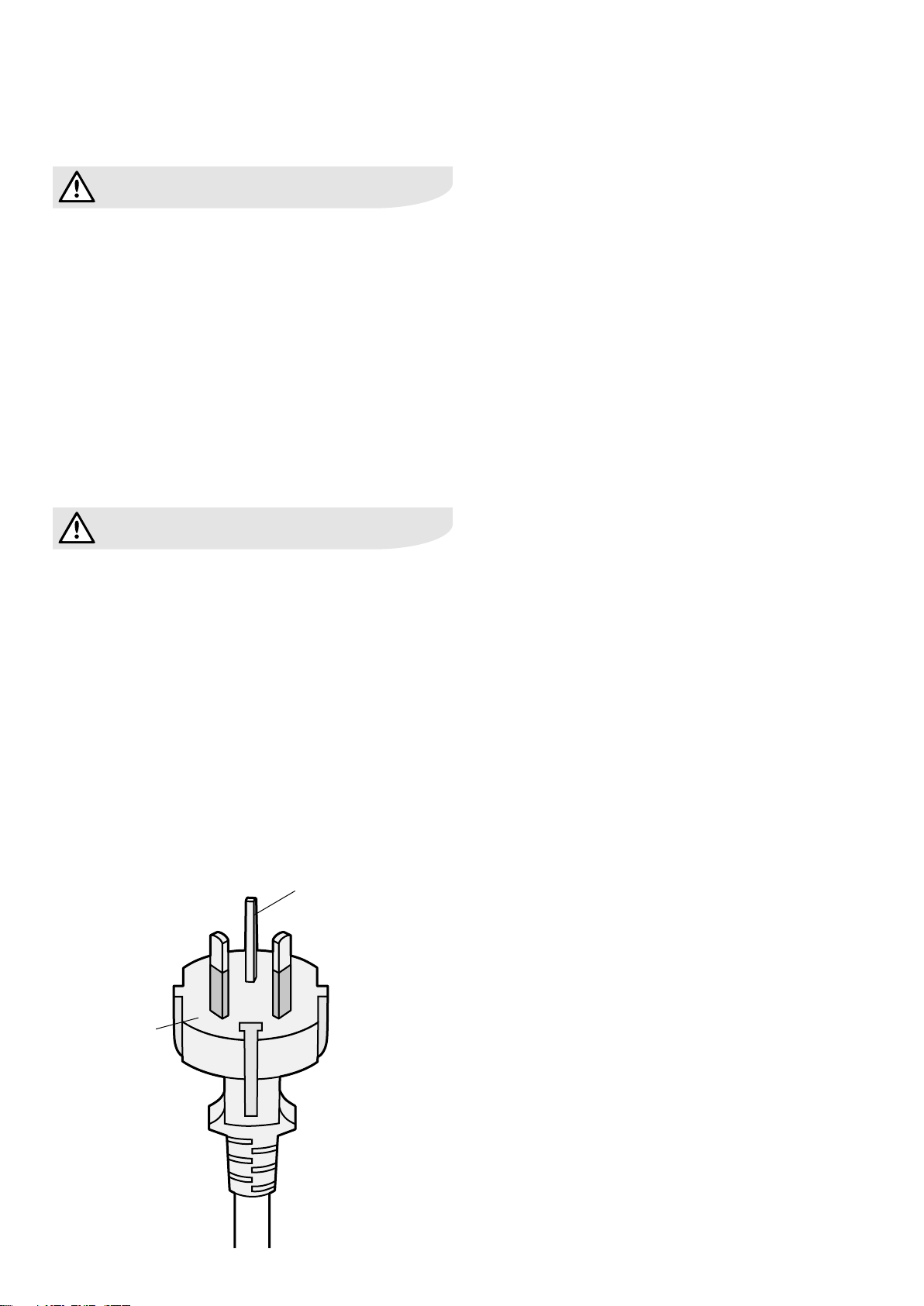
• This appliance must be earthed. This appliance is
equipped with a cord having an earth wire. The plug
must be plugged into an outlet that is properly installed
and earthed.
Usage cautions
• Ventilate the room periodically during use, especially if using
gas appliances in conjunction with the air conditioner.
• Be sure to turn the unit off and disconnect the power
supply cord before performing any maintenance
or cleaning.
• Do not splash or pour water directly onto the unit.
Water can cause electrical shock or equipment damage.
• Drainage should be performed whenever moving the air
conditioner (see page 20). If any water remains in the
tank, it may spill out while being moved.
• To ensure proper drainage, the drainage hose must
have no kinks and must not be elevated during
dehumidification mode. If not, the drained water may
spill out into the room.
• The temperature around the drainage hose must not
be below freezing point when used. Drained water may
freeze inside the hose, causing water inside the unit to
overflow into the room.
• Do not block the exhaust air outlet with obstacles.
Cooling performance may be reduced or stop completely.
• Provide a residual current device (RCD) in order to
protect against electric shock in accordance with
Australian Standard and Wiring Rules.
• Exposure to direct airflow for an extended period of
time could be hazardous to your health. Do not expose
occupants, pets, or plants to direct airflow for extended
periods of time.
• Do not use this air conditioner for non-specified special
purposes (e.g. preserving precision devices, food, pets,
plants, and art objects). Usage in such a manner could
harm such property.
Notes on operation
• Allow 3 minutes for the compressor to restart cooling.
If you turn the air conditioner off and immediately restart
it, allow three minutes for the compressor to restart
cooling. There is an electronic device in the unit that
keeps the compressor turned off for three minutes
for safety.
• In the event of a power failure during use, allow 3
minutes before restarting the unit. After power is
reinstated, restart the air conditioner. If the power was
off for less than three minutes, be sure to wait at least
three minutes before restarting the unit. If you restart
the air conditioner within three minutes, a protective
device in the unit may cause the compressor to shut off.
This protective device will prevent cooling for about 5
minutes. Any previous settings will be cancelled and the
unit will return to its initial settings.
• Low temperature operation: Is your unit freezing up?
Freezing may occur when the unit is set close to 18°C in
low ambient temperature conditions, especially at night.
In these conditions, a further temperature drop may
cause the unit to freeze. Setting the unit to a higher
temperature will prevent it from freezing.
• Dehumidification mode increases room temperature.
The unit generates heat during dehumidification mode
and the room temperature will rise. Warm air will be
blown out from the Exhaust air outlet, but this is normal
and does not indicate a problem with the unit.
• This air conditioner blows the warm air generated by
the unit outside the room via the exhaust hose while in
cool mode. Accordingly, the same amount of air as that
blown out will enter the room from outside through any
openings into the room.
plug
earth pin
• The air conditioner must be operated within the
temperature range indicated in the table below.
• Available for operation at condition of supply voltage
220V to 240V at 50Hz.
• A built-in safety device may cut off operation if the
temperature exceeds these limits.
• When cooling operation is performed at high room
temperature, the fan may run slightly slower.
Mode Room temperature
Cool upper limit 35°C
lower limit 18°C
Dehumidification lower limit 15°C
Energy efficiency tips
• Avoid direct sunlight
Close blinds, drapes or shades to keep out direct
sunlight while in cooling mode.
• Keep the filter clean
Keeping the filter clean greatly aids efficient operation.
A dirty filter blocks the flow of air, making your air
conditioner work harder and less efficiently.
See page 18 on how to clean the filter.
• Turn off unnecessary lights
Your air conditioner must remove the heat produced by
your lights or other heat-producing appliances. Turn off
any lights or appliances that are not in use.
• Turn off the air conditioner when no one is home
Use only when necessary. The less time the air
conditioner is used, the lower the running costs.
Location
• The air conditioner should be placed on a firm
foundation to minimize noise and vibration. For safe and
secure positioning, place the unit on a smooth, level
floor strong enough to support the unit.
• The unit has casters to aid placement, but it should only
be rolled on smooth, flat surfaces. Use caution when
rolling on carpet surfaces. Do not attempt to roll the unit
over objects.
• The unit must be placed within reach of a properly rated
earthed socket.
• Never place any obstacles around the air inlet or outlet
of the unit.
• Allow at least 30 cm of space on either side from the
wall for efficient air-conditioning.
Included
Suggested tools for window kit installation
1. Screwdriver (medium size Phillips)
2. Tape measure or ruler
3. Knife or scissors
4. Saw (in the event that the window panel needs to be cut
down in size because the window is too narrow for direct
installation)
MIN. 30 cm
MIN. 30 cm
Exhaust hose (1) Window exhaust adapter (1)
Insect guard net (1)
Battery (2)
(AAA.1.5V)
Manual (1)
Bracket (1)
Bushing (1)
Foam seal (1) Foam seal (3)
(adhesive type) A
Foam seal (1)
(adhesive type) B
Window panel (1)
Exhaust cover (1)
Adjustment panel (1)
Extension panel (1)
Rain guard (2)
Screw (8)
Drain
hose (1)
Remote control (1)
Hose clamp (1)
Operating conditions
4 operating conditions/included electrolux EPV09CRA & EPV12CRA
Remote control hoo
k
Loading the batteries (use two AAA 1.5V) alkaline
batteries
1. Remove the battery cover at the back of the
remote control.
2. Insert batteries into the compartment, making sure
the and polarities are correctly aligned, as shown.
• Lines will appear on the display when batteries are
properly installed.
3. Reattach the battery cover.
4. Press the RESET button using a thin pointed implement.
NOTES:
• Batteries should last approximately one year under
normal use.
• When replacing the batteries, always change both
batteries at the same time, and make sure they are the
same type.
• If the remote control does not operate normally after
replacing the batteries, press the RESET button using a
thin pointed implement.
• If you will not be using the unit for a prolonged period,
remove the batteries from the remote control.
• Do not use rechargeable batteries.
Using the remote control
Battery cove
r
Pointed implement
Lines
Point the remote control towards the units signal receiver
window and press the desired button. A beep will sound
when the unit receives the signal.
• Make sure nothing, such as curtains, block the signal
receiver window.
• The remote control operates up to 7 meters away.
caution
• Do not expose the signal receiver window to direct
sunlight. This may adversely affect its operation. If
necessary, close curtains to block out the sunlight.
• Use of a fluorescent lamp in the same room may
interfere with transmission of the signal.
• The unit may be affected by signals emitted from
other remote controllers for televisions, VCRs or other
equipment used in the same room.
• Do not leave the remote control exposed to direct
sunlight or near a heater. Protect the remote control
from moisture and shock which can discolour or
damage it.
To prevent the remote control from being misplaced, hook it
to the unit when not in use.
When attached, to remove the remote control from the unit,
lift the remote control up slightly and pull it out from the
remote control hook.
How to use the remote control
Remote control hoo
k
electrolux EPV09CRA & EPV12CRA using the remote control 5
6 installation of window kit electrolux EPV09CRA & EPV12CRA
Installation in a double-hung sash window
1. Connect the rain guards to the insect guard net.
• Insert all three projections on each rain guard into the
holes in the insect guard net.
• Side “A” will now be uppermost, as indicated in the
diagram.
2. Attach the bushing into the hole of the window panel.
• This bushing can be used as a point to run the drain
hose for external drainage.
3. Attach the guard combined above to the window panel
• Push the insect guard net firmly to ensure that its four
projections fit into the holes in the window panel.
• Side “A” will now be at the top, as indicated in the
diagram.
Installation of window kit
Window panel
559mm - 609mm
Window sill
Hole
Projection
Insect guard
net
Rain guard
“A”
Bushing
Window panel
Window panel
Projection
“A”
Foam seal A
(adhesive type)
Adjustment panel
Exhaust cover
Window
panel
Cut
Window panel
559mm - 609mm
Window sill
Hole
Projection
Insect guard
net
Rain guard
“A”
Bushing
Window panel
Window panel
Projection
“A”
Foam seal A
(adhesive type)
Adjustment panel
Exhaust cover
Window
panel
Cut
4. Cut the foam seal A (adhesive type) to the proper length
and attach it to the window sill
5. Attach the window panel to the window sill
(A) If the inner width of the window is between 559mm and
609mm inclusive:
The window panel cannot be installed in windows less
than 559mm wide, as you will be unable to shut the
exhaust cover.
In such cases the exhaust cover will have to be removed
prior to installing the window panel.
• Remove the adjustment panel from the window panel,
and cut the window panel to the same width as the
window
• Open the window sash and place the window panel
on the window sill
• Secure the window panel to the window stool with 2
screws
Window panel
559mm - 609mm
Window sill
Hole
Projection
Insect guard
net
Rain guard
“A”
Bushing
Window panel
Window panel
Projection
“A”
Foam seal A
(adhesive type)
Adjustment panel
Exhaust cover
Window
panel
Cut
Window panel
559mm - 609mm
Window sill
Hole
Projection
Insect guard
net
Rain guard
“A”
Bushing
Window panel
Window panel
Projection
“A”
Foam seal A
(adhesive type)
Adjustment panel
Exhaust cover
Window
panel
Cut
Window panel
559mm - 609mm
Window sill
Hole
Projection
Insect guard
net
Rain guard
“A”
Bushing
Window panel
Window panel
Projection
“A”
Foam seal A
(adhesive type)
Adjustment panel
Exhaust cover
Window
panel
Cut
electrolux EPV09CRA & EPV12CRA installation of window kit 7
Installation in a double-hung sash window (cont.)
(B) If the inner width of the window is between 609mm and
934mm inclusive:
• Open the window sash and place the window panel
on the window stool.
• Slide the adjustment panel to fit the window frame
width.
• Secure the window panel to the sill with 3 screws.
(C) If the inner width of the window is between 934mm and
1219mm inclusive:
• Attach the extension panel to the adjustment panel.
• Open the window sash and place the window panel
on the window stool.
• Slide the adjustment and extension panels to fit the
window frame width.
• Secure the window panel to the window stool with
4 screws.
Adjustment panel
609mm - 934mm
Extension panel
934mm - 1219mm
Foam seal A
(adhesive type)
Foam seal B
(adhesive type)
Foam seal
Bracket
6. Cut the foam seals A and B (adhesive type) to the proper
length and attach it to the window panel
• Attach foam seal A to the window panel and extension
panel, and attach foam seal B to the adjustment panel.
7. Close the window sash securely against the window
panel
8. Cut the foam seal to an appropriate length and seal the
opening between the top of the inner window sash and
the outer window sash
9. Attach a bracket with the screw
Adjustment panel
609mm - 934mm
Extension panel
934mm - 1219mm
Foam seal A
(adhesive type)
Foam seal B
(adhesive type)
Foam seal
Bracket
Adjustment panel
609mm - 934mm
Extension panel
934mm - 1219mm
Foam seal A
(adhesive type)
Foam seal B
(adhesive type)
Foam seal
Bracket
Adjustment panel
609mm - 934mm
Extension panel
934mm - 1219mm
Foam seal A
(adhesive type)
Foam seal B
(adhesive type)
Foam seal
Bracket
Adjustment panel
609mm - 934mm
Extension panel
934mm - 1219mm
Foam seal A
(adhesive type)
Foam seal B
(adhesive type)
Foam seal
Bracket
Adjustment panel
609mm - 934mm
Extension panel
934mm - 1219mm
Foam seal A
(adhesive type)
Foam seal B
(adhesive type)
Foam seal
Bracket
Installation in a sliding sash window
1. Connect the rain guards to the insect guard net
• Insert all three projections on each rain guard into the
holes in the insect guard net.
• Side “A” will now be uppermost, as indicated in the
diagram.
2. Attach the bushing into the hole of the window panel
• The bushing can be used as a point to run the drain
hose for external drainage.
3. Attach the guard combined with insect guard net to the
window panel
• Push the insect guard net firmly to ensure that its four
projections fit into the holes in the window panel.
• Side “A” will now be at the top, as indicated in the
diagram, when it is installed in the window.
Foam seal A
(adhesive type)
Window
panel
559mm - 609mm
Hole
Projection
Insect guard net
Rain guard
“A”
Window
panel
Projection
“A”
Window
panel
Bushing
Adjustment panel
Exhaust cover
Window
panel
Cut
8 installation of window kit electrolux EPV09CRA & EPV12CRA
4. Cut the foam seal A (adhesive type) to the proper length
and attach it to the window frame
5. Install the window panel into the window frame
(A) If the inner height of the window is between 559mm and
609mm inclusive:
The window panel cannot be installed in windows less
than 559mm high, as you will be unable to shut the
exhaust cover.
In such cases the exhaust cover will have to be removed
prior to installing the window panel.
• Remove the adjustment panel from the window panel,
and cut the window panel to the same height as the
window.
• Open the window sash and place the window panel
on the window frame.
• Secure the window panel to the window frame with
2 screws.
Foam seal A
(adhesive type)
Window
panel
559mm - 609mm
Hole
Projection
Insect guard net
Rain guard
“A”
Window
panel
Projection
“A”
Window
panel
Bushing
Adjustment panel
Exhaust cover
Window
panel
Cut
Foam seal A
(adhesive type)
Window
panel
559mm - 609mm
Hole
Projection
Insect guard net
Rain guard
“A”
Window
panel
Projection
“A”
Window
panel
Bushing
Adjustment panel
Exhaust cover
Window
panel
Cut
Foam seal A
(adhesive type)
Window
panel
559mm - 609mm
Hole
Projection
Insect guard net
Rain guard
“A”
Window
panel
Projection
“A”
Window
panel
Bushing
Adjustment panel
Exhaust cover
Window
panel
Cut
Foam seal A
(adhesive type)
Window
panel
559mm - 609mm
Hole
Projection
Insect guard net
Rain guard
“A”
Window
panel
Projection
“A”
Window
panel
Bushing
Adjustment panel
Exhaust cover
Window
panel
Cut
electrolux EPV09CRA & EPV12CRA installation of window kit 9
Installation in a sliding sash window (cont.)
(B) If the inner height of the window is between 609mm and
934mm inclusive:
• Open the window sash and place the window panel
on the window frame.
• Slide the adjustment panel to fit the window frame
height.
• Secure the window panel to the window frame with 3
screws.
(C) If the inner height of the window is between 934mm and
1219mm inclusive:
• Attach the extension panel to the adjustment panel.
• Open the window sash and place the window panel
on the window frame.
• Slide the adjustment and extension panels to fit the
window frame height.
• Secure the window panel to the window frame with 4
screws.
Adjustment
panel
609mm - 934mm
934mm - 1219mm
Foam seal A
(adhesive type)
Foam seal B
(adhesive type)
Extension panel
Foam seal
Bracket
6. Cut the foam seals A and B (adhesive type) to the proper
length and attach them to the window panel
• Attach foam seal A to the window panel and extension
panel, and attach foam seal B to the adjustment panel.
7. Close the window sash securely against the window
panel
8. Cut the foam seal to an appropriate length and seal the
opening between the side of the inner window sash and
the outer window sash
9. Attach a bracket with the screw
Adjustment
panel
609mm - 934mm
934mm - 1219mm
Foam seal A
(adhesive type)
Foam seal B
(adhesive type)
Extension panel
Foam seal
Bracket
Adjustment
panel
609mm - 934mm
934mm - 1219mm
Foam seal A
(adhesive type)
Foam seal B
(adhesive type)
Extension panel
Foam seal
Bracket
Adjustment
panel
609mm - 934mm
934mm - 1219mm
Foam seal A
(adhesive type)
Foam seal B
(adhesive type)
Extension panel
Foam seal
Bracket
Adjustment
panel
609mm - 934mm
934mm - 1219mm
Foam seal A
(adhesive type)
Foam seal B
(adhesive type)
Extension panel
Foam seal
Bracket
Adjustment
panel
609mm - 934mm
934mm - 1219mm
Foam seal A
(adhesive type)
Foam seal B
(adhesive type)
Extension panel
Foam seal
Bracket

This manual suits for next models

1

Other Electrolux Air Conditioner manuals

Electrolux EXP09HSECI User manual

Electrolux

Electrolux EXP09HSECI User manual

Electrolux CXl09HL1W User manual

Electrolux

Electrolux CXl09HL1W User manual

Electrolux R410A User manual

Electrolux

Electrolux R410A User manual

Electrolux EXP09 User manual

Electrolux

Electrolux EXP09 User manual

Electrolux WAC060K7A User manual

Electrolux

Electrolux WAC060K7A User manual

Electrolux Frigidaire GHWQ083WC1 Owner's manual

Electrolux

Electrolux Frigidaire GHWQ083WC1 Owner's manual

Electrolux MSG-07HRIN2 User manual

Electrolux

Electrolux MSG-07HRIN2 User manual

Electrolux EACS/I-HAV/N8_22Y EEC User manual

Electrolux

Electrolux EACS/I-HAV/N8_22Y EEC User manual

Electrolux EL-KFR26G/TN2Y-A Operating manual

Electrolux

Electrolux EL-KFR26G/TN2Y-A Operating manual

Electrolux EXH09HV1W User manual

Electrolux

Electrolux EXH09HV1W User manual

Electrolux EXS09JEIW User manual

Electrolux

Electrolux EXS09JEIW User manual

Electrolux EASE09P5AHLW User manual

Electrolux

Electrolux EASE09P5AHLW User manual

Electrolux EACM-09 HR/N6 User manual

Electrolux

Electrolux EACM-09 HR/N6 User manual

Electrolux ERS09E37HW Service manual

Electrolux

Electrolux ERS09E37HW Service manual

Electrolux EAS(C User manual

Electrolux

Electrolux EAS(C User manual

Electrolux BCCHS-7I User manual

Electrolux

Electrolux BCCHS-7I User manual

Electrolux EXP09CN1W7 User manual

Electrolux

Electrolux EXP09CN1W7 User manual

Electrolux BCC-12I User manual

Electrolux

Electrolux BCC-12I User manual

Electrolux EXP12HN1W6 User manual

Electrolux

Electrolux EXP12HN1W6 User manual

Electrolux EXS09V38HW User manual

Electrolux

Electrolux EXS09V38HW User manual

Electrolux ESV123C1AA User manual

Electrolux

Electrolux ESV123C1AA User manual

Electrolux FAM18EQ2 User manual

Electrolux

Electrolux FAM18EQ2 User manual

Electrolux EPS09V57HW User manual

Electrolux

Electrolux EPS09V57HW User manual

Electrolux FAH105N1 User manual

Electrolux

Electrolux FAH105N1 User manual

Popular Air Conditioner manuals by other brands

Gree GWH18TC-K3DNA1B/I Service manual

Gree

Gree GWH18TC-K3DNA1B/I Service manual

CH CH-PDH12AC1 owner's manual

CH

CH CH-PDH12AC1 owner's manual

Snap-On POLARTEK EEAC330B manual

Snap-On

Snap-On POLARTEK EEAC330B manual

Mitsubishi Electric MSZ-DM25VA operating instructions

Mitsubishi Electric

Mitsubishi Electric MSZ-DM25VA operating instructions

Fujitsu ASTA30LFC Service manual

Fujitsu

Fujitsu ASTA30LFC Service manual

EMI WLCA operation instruction

EMI

EMI WLCA operation instruction

MegaLife NEBULA GREEN R32 Use and Installation Instructions

MegaLife

MegaLife NEBULA GREEN R32 Use and Installation Instructions

Mitsubishi Electric PLA-SP BA Series Operation manual

Mitsubishi Electric

Mitsubishi Electric PLA-SP BA Series Operation manual

PR KLIMA GPC10AL operating instructions

PR KLIMA

PR KLIMA GPC10AL operating instructions

Technibel MCAV77C5VAB Technical data & service manual

Technibel

Technibel MCAV77C5VAB Technical data & service manual

Frigicoll MKD-V300 Installation & owner's manual

Frigicoll

Frigicoll MKD-V300 Installation & owner's manual

Frigidaire FAS155K1A1 Factory parts catalog

Frigidaire

Frigidaire FAS155K1A1 Factory parts catalog

Dimplex DCES09 manual

Dimplex

Dimplex DCES09 manual

Daikin FAQ71CVEB installation manual

Daikin

Daikin FAQ71CVEB installation manual

Vogue 373008 Installation instructions & user guide

Vogue

Vogue 373008 Installation instructions & user guide

Samsung AR Series user manual

Samsung

Samsung AR Series user manual

Panasonic U-8ME2E8 Service Manual & Test Run Service Manual

Panasonic

Panasonic U-8ME2E8 Service Manual & Test Run Service Manual

TCL CWH09TBAI Service manual

TCL

TCL CWH09TBAI Service manual

manuals.online logo
manuals.online logoBrands
  • About & Mission
  • Contact us
  • Privacy Policy
  • Terms and Conditions

Copyright 2025 Manuals.Online. All Rights Reserved.