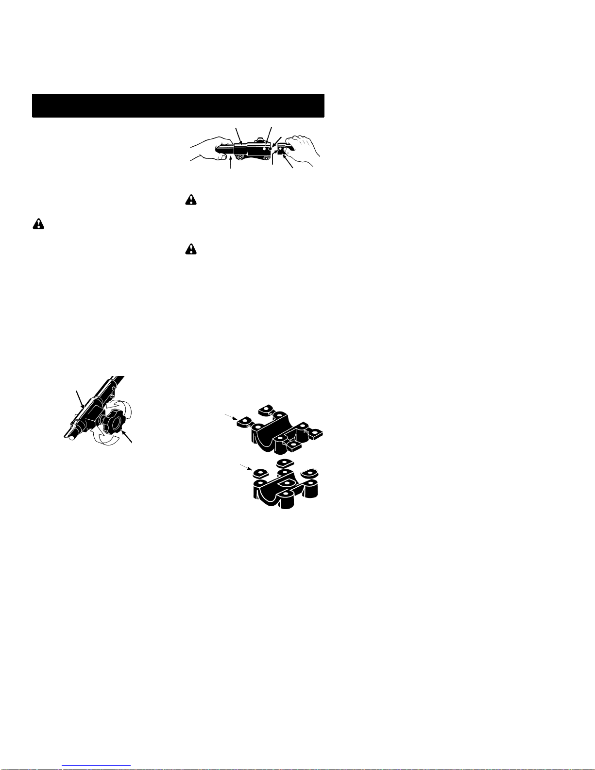
Electrolux U4000C User manual

ENGLISH ESPAÑOL FRANÇAIS
DANGER:
Read and follow all Safety Rules and Operating Instructions before
using this product. Failure to do so can result in serious injury.
PELIGRO:
Lea el manual de instrucciones y siga todas las advertencias e
instrucciones de seguridad. El no hacerlo puede resultar en le-
siones graves.
DANGER:
Lirelemanueld’instructionsetbienrespectertouslesavertisse-
ments et toutes les instructions de sécurité. Tout défaut de le
faire pourrait entraîner des blessures graves.
Instruction Manual
Manual de Instrucciones
Manuel d’Instructions
U4000C
Electrolux Home Products, Inc.
250 Bobby Jones Expressway
Augusta, GA 30907
Copyright E2003 Electrolux Home Products, Inc. 530164695 12/8/03
NOT DESIGNED FOR USE WITH
ELECTRIC POWERHEADS
NO ESTA DISEÑADO PARA EL USO CON
CABEZAS DE MOTOR ELÉCTRICO
NON CONÇU POUR L’USAGE AVEC
BLOC---MOTEURS ÉLECTRIQUES
BRUSHCUTTER
ATTACHMENT

2
IDENTIFICATION OF SYMBOLS
DANGER! This brushcutter
can be dangerous! Careless or
improper use can cause
serious or even fatal injury.
Read and understand the
instruction manual before
using the brushcutter.
Alwayswearappropriateearprotection,eyeprotectionandheadprotection.
SAFETY RULES
WARNING: When using gardening
appliances, basic safety precautions should
always be followed to reduce the risk of fire
andseriousinjury. Readandfollowallinstruc-
tions. Failureto do so can result in serious in-
jury.
DANGER:This powertoolcanbedan-
gerous! This unit can cause serious injury in-
cluding amputation or blindness to the opera-
tor and others. The warnings and safety
instructionsinthis manualmust befollowedto
provide reasonable safety and efficiency in
using the unit. The operatoris responsible for
following the warnings and instructions in this
manual and on the unit. Read the entire in-
structionmanualbeforeassemblingandusing
theunit!Restrict theuse ofthis unit topersons
who read, understand, and follow the warn-
ingsandinstructionsinthis manualandonthe
unit. Never allow children to operate this unit.
SAFETY INFORMATION
ON THE UNIT
INSTRUCTION
MANUAL
DANGER:Neveruseflailing devices.
DANGER: Blade can thrust violently
away from material it does not cut. Blade
thrust can cause amputation of arms or legs.
Keep people andanimals 50 feet (15 meters)
away.
WARNING: Blade can throw objects
violently. You can be blinded or injured. Wear
eye and leg protection.
Leg
Guards
Boots
Eye
Protection
ALWAYS WEAR:
Thrown
objects
WARNING: Hazard zone for thrown
objects. Blade can throw objects violently.
Otherscan beblinded orinjured.Keeppeople
and animals 50 feet (15 meters) away.
Hazard Zone
50 feet
(15 meters)
WARNING: The blade continues to
spin after throttle is released or engine is
turned off. The coasting blade can throw ob-
jects or seriously cut you if accidentally
touched. Stop theblade by contacting the left
hand side of coasting blade with material al-
ready cut.

3
Stop coasting
blade by contact
with cut material.
OPERATOR SAFETY
SDressproperly.Alwayswearsafetyglasses
or similar eye protectionwhen operating,or
performingmaintenance onyour unit (safe-
ty glasses are available). Eye protection
should be marked Z87.
SAlways wear face or dust mask if operation
is dusty.
SAlways wear heavy, long pants, long
sleeves, boots, and gloves. Wearingsafety
leg guards is recommended.
SAlways wear foot protection. Do not go
barefoot or wear sandals.
SSecure hair above shoulder length. Secure
or remove loose clothing and jewelry or
clothing with loosely hanging ties, straps,
tassels, etc. They can be caught in moving
parts.
SBeing fully covered also helps protect you
from debris and pieces of toxic plants
thrown by spinning blade.
SStayalert.Donotoperateunitwhenyouare
tired,ill, upset or under influence ofalcohol,
drugs, or medication. Watch what you are
doing; use common sense.
SWear hearing protection.
SNeverstartorruntheengineinsideaclosed
room or building. Breathing exhaust fumes
can kill.
SKeep handles free of oil and fuel.
SAlways use the handlebar and a properly
adjusted shoulder strap when using brush-
cutter attachment (see ASSEMBLY).
UNIT/MAINTENANCESAFETY
WARNING: Disconnect powerhead
spark plug (or disconnect powerhead from pow-
er source) before performing maintenance.
SLook for and replace damaged or loose
parts before each use. Look for and repair
fuel leaks before use. Keep unit in good
working condition.
SThrow away blades that are bent, warped,
cracked, broken, or damaged in any other
way. Replace trimmer head parts that are
cracked, chipped, broken, or damaged in
any other way before using the unit.
SMaintain the unit according to recom-
mendedprocedures.Keepthebladesharp.
Never use flailing devices, wire, rope,
string, etc.
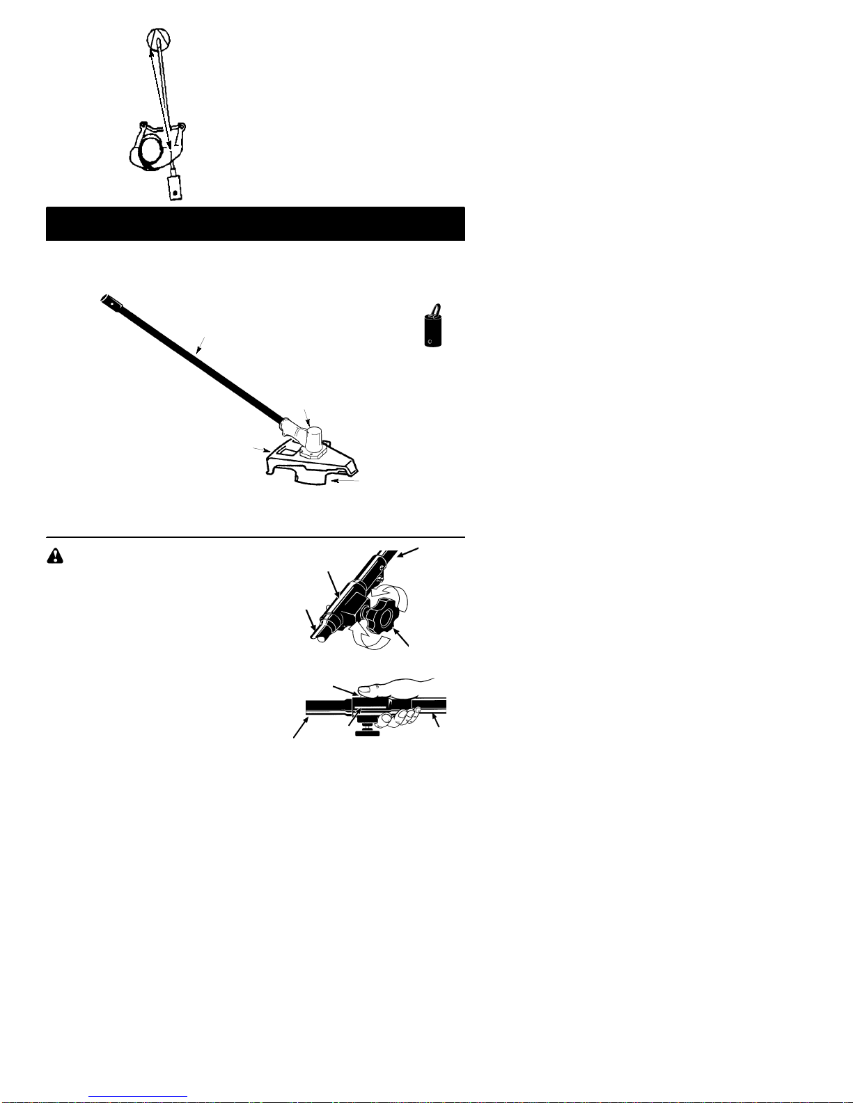
SUse only specified blade; make sure it is
properly installed and securely fastened.
SNever start engine with clutch shroud re-
moved. Theclutch can fly off and cause se-
rious injury.
SBe sure blade stops turning when engine
idles.
SMakecarburetoradjustmentswiththelower
end supported to prevent the blade from
contactinganyobject.Holdtheunitbyhand;
do not use the shoulder strap for support.
SKeep others away when making carburetor
adjustments.
SUse only recommended Poulan/Weed
Eater!accessories and replacement parts.
SHave all maintenance and service not ex-
plained in this manual performedby an au-
thorized service dealer.
FUEL SAFETY
SMix and pour fuel outdoors.
SKeep away from sparks or flames.
SUse a container approved for fuel.
SDo not smoke or allow smoking near fuel or
the unit or while using the unit.
SAvoid spilling fuel or oil. Wipe up all fuel
spills before starting engine.
SMove at least 10 feet (3 meters) away from fu-
eling site before starting engine.
SStop engine and allow it to cool before re-
moving fuel cap.
SRemove fuel cap slowly.
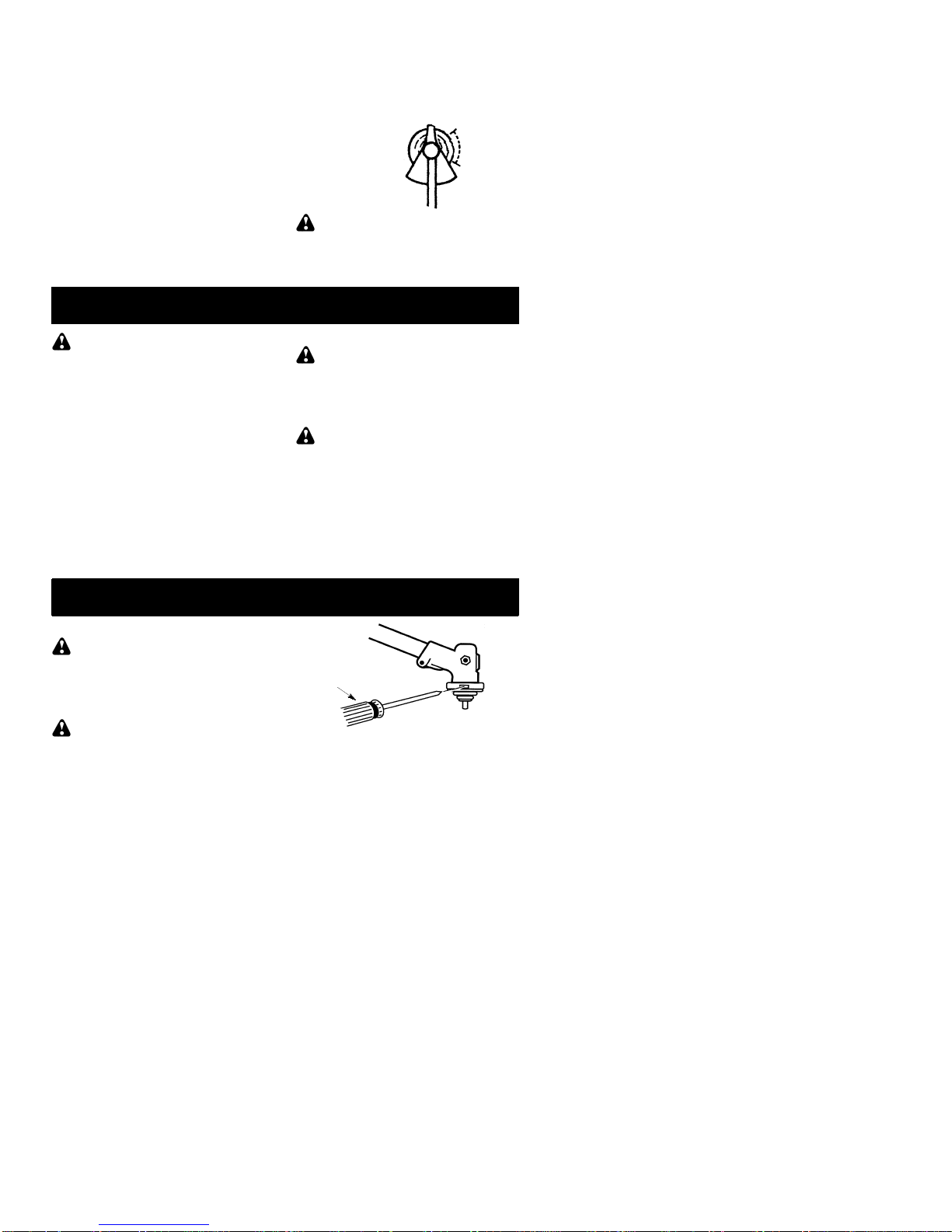
CUTTING SAFETY
WARNING:Inspect the areato be cut
beforeeachuse.Removeobjects(rocks,bro-
ken glass, nails, wire, string, etc.) which can
be thrown or become entangled in the blade.
SKeepothersincludingchildren,animals,by-
standers, and helpers at least 50 feet (15
meters) away. Stopthe engine immediately
if you are approached.
SAlways keep engine on theright--handside
of your body.
SHold the unit firmly with both hands.
SKeepfirm footingand balance. Donot over-
reach.
SKeep blade below waist level.
SDo not raise powerhead engine above your
waist.
SKeepall partsof your bodyaway fromblade
and muffler.
SCut from your left to your right. Cutting on
the right side of the shield will throw debris
away from the operator.
SUse only in daylight or good artificial light.
SUse only for jobs explained in this manual.
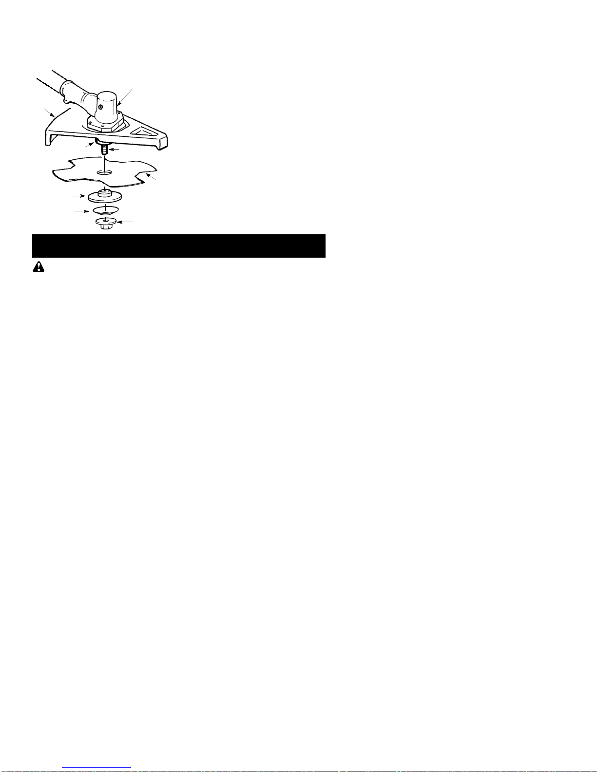
TRANSPORTINGAND STORAGE
SStopthe powerheadengine beforecarrying
unit.
SKeep muffler away from your body.
SAllow engine to cool andsecure unit before
storing or transporting it in a vehicle.
SEmpty the fuel tank before storing or trans-
portingtheunit.Use upfuel left in thecarbu-
retor by starting the engine andletting it run
until it stops.
SStoreunitand fuel in an areawhere fuelva-
pors cannot reach sparks or open flames
from water heaters, electric motors or
switches, furnaces, etc.
SStore unit so the blade cannot accidentally
cause injury.
SStore unit indoors, out of reach of children.
If situations occur which are not covered in this
manual, use care and good judgment. If you
need assistance, call 1--800--554--6723.

4
SPECIALNOTICE:Exposuretovibrations
through prolonged use of gasoline powered
handtools could cause bloodvessel or nerve
damage in the fingers, hands, and joints of
peoplepronetocirculationdisordersorabnor-
mal swellings. Prolongeduse in cold weather
has been linked to blood vessel damage in
otherwise healthy people. If symptoms occur
such as numbness, pain, loss of strength,
change in skin color or texture, or loss of feel-
ing inthe fingers,hands,or joints,discontinue
theuseofthistoolandseekmedicalattention.
An anti-vibration system does not guarantee
the avoidance of these problems. Users who
operatepowertoolsonacontinualandregular
basis must monitor closely their physical
condition and the condition of this tool.
SAVE THESE INSTRUCTIONS
ASSEMBLY
CARTON CONTENTS
Check carton contents for the following:
SBrushcutter attachment
SHandlebar (with clamp and knob)
SHandlebar clamp base (with spacer tabs)
SShoulder strap
SUpper shoulder strap clamp
SLower shoulder strap clamp (with spacer
tabs)
SHandlebar clamp screws (4)
SShoulder strap clamp screws (2)
SAttachment hanger
SHex wrench
WARNING: If received assembled, re-
peat all steps to ensure your unit is properly as-
sembled and all fasteners are secure.
Examine parts for damage. Do not use dam-
aged parts.
NOTE:Ifyouneedassistanceorfindthatparts
are missing or damaged, call 1-800-554-6723.
TOOLS REQUIRED
SHex wrench (provided)
INSTALLING BRUSHCUTTERAT-
TACHMENT
CAUTION: When removing or installing at-
tachments, place the unit on a flat surfacefor
stability.
1. Loosen the coupler by turning the knob
counterclockwise.
Coupler
Knob
LOOSEN
TIGHTEN
2. Remove the shaft cap fromthebrushcut-
ter attachment (if present).
3. Position locking/release button of attach-
ment into guide recess of coupler.
4. Pushtheattachmentintothecoupleruntil
the locking/release buttonsnaps into the
primary hole.
5. Beforeusingtheunit,tightentheknobse-
curely by turning clockwise.
Coupler Primary Hole
Upper
Shaft Locking/
Release
Button
Lower
Attachment
Guide Recess
WARNING:Makesurethelocking/re-
lease button is locked in the primary hole and
the knob is securely tightened before operat-
ing the unit.
HANDLEBARASSEMBLY
DANGER: RISK OF CUT. To avoid
seriousinjury,thebarrier portionof the handlebar
must be installed as shown on the upper shaft of
the powerhead to provide a barrier between op-
erator and the spinning blade. Attach shaft
clamp above arrow on safety warning decal on
the upper shaft (powerhead end of unit). Ensure
handlebar is positioned on handlebar clamp be-
tween the arrows on the handlebar decal.
NOTE: The shaft clamp base has four
spacer tabs attached. These tabs are pro-
vided to adapt this attachment for use with
powerheads that have a 1"diameter upper
shaft(theshaftclampwill nottightendownse-
curely on the 1"diameter upper shaft without
using these spacer tabs). The tabs must be
broken off completely before use and placed
over the screw holes on the clamp base.
These tabs are not needed for powerheads
with a 7/8"upper shaft.
Spacer Tabs
HANDLEBARCLAMP BASE
Spacer Tabs
positioned for use
on 1"diameter
upper shaft
1. Place the shaft clamp over the upper
shaftabovethearrowonthesafetydecal.

5
2. Position the clamp base under the upper
shaftandaligntheshaftclampandclamp
base screw holes (use spacer tabs be-
tweenshaftclampandclampbaseifnec-
essary tosecure clamp, i.e. for1"diame-
ter upper shaft).
POWERHEAD
END
ATTACHMENT
END
Screws
Clamp
Base
Handlebar Clamp
between arrows on
handlebar decal
Clamp
Knob
Shaft
Clamp
Handlebar
Arrow on
Safety Decal
3. Insert the four screws into the screw
holes.
4. Secure shaft clamp by tightening screws
with the hex wrench.
5. Position the handlebaras shown, ensur-
ing the handlebar is positioned on the
handlebar clamp between the arrows on
the handlebar decal.
6. Retighten handlebar by turning clamp
knob clockwise until handlebar is secure
andstationaryinclamp(clamp knobcan-
not be overtightened).
SHOULDER STRAP ASSEMBLY
WARNING: Proper shoulder strap
and handlebar adjustments must be made
withtheenginecompletely stoppedbeforeus-
ing unit. The shoulder strap clamp must be
installed as shown above the handlebar on the
upper shaft (powerhead end of unit).
NOTE: The lower shoulder strap clamp has
twospacertabsattached. Thesetabs arepro-
vided to adapt this attachment for use with
powerheads that have a 1"(2.5 cm) diameter
upper shaft (the shoulder strapclamp will not
tightendownsecurelyonthe1"(2.5cm)diam-
eter upper shaft without using these spacer
tabs). Thetabsmustbebrokenoffcompletely
before use and placed over the screw holes
onthelowershoulderstrapclamp. Thesetabs
are not needed for powerheads with a 7/8"
(2.2 cm) upper shaft.
Spacer Tabs
LOWER SHOULDER STRAP
CLAMP
Spacer Tabs
positioned for use
on 1"(2.5 cm)
diameter
upper shaft
1. Place the upper shoulder strap clamp
overtheuppershaftabovethehandlebar.
2. Position the lower shoulder strap clamp
undertheuppershaftandaligntheupper
and lower clamp screw holes (use
spacer tabs between upper and lower
clamps if necessary to secure clamp, i.e.
for 1"(2.5 cm) diameter upper shaft).
Upper Shoulder
Strap Clamp
Screws
Lower Shoulder
Strap Clamp
POWERHEAD
END
ATTACHMENT
END
3. Insert two screws into the screw holes.
4. Secure shoulder strap clamp by tighten-
ing screws with the hex wrench.
5. Insert your right arm and head through
the shoulder strap and allow it to rest on
your left shoulder. Make sure the danger
sign is onyourback andthe hookis tothe
right side of your waist.
NOTE:A one-halftwist is builtin theshoulder
straptoallowthestraptorestflatontheshoul-
der.
6. Adjust the strap, allowing the hook to be
about 6 inches below the waist.
7. Fasten the strap hook to the clamp and lift
the tool to the operating position.
8. Try on shoulder strap and adjust for fit
andbalancebeforestartingtheengineor
beginning a cutting operation.
NOTE: It may be necessary to relocate the
shoulder strap clamp on the shaft for proper
balancing of unit.
30 inches
(76 cm)
HARNESS
ADJUSTMENT
FOR BALANCE
6 inches
(15 cm)
below
waist
4--12
inches
(10 -- 30 cm)
above
ground

6
30 inches
(76 cm)
OPERATION
KNOW YOUR BRUSHCUTTERATTACHMENT
READ THIS INSTRUCTION MANUAL AND SAFETY RULES BEFORE OPERATING YOUR
BRUSHCUTTERATTACHMENT. Comparetheillustrations with your unitto familiarize yourself
with the location of various controls and adjustments. Save this manual for future reference.
Blade Shield
Blade
Gearbox
Shaft Hanger
BLADE
The BLADE is designed for cutting grass,
weeds, and brush up to 1/2 inch (1 cm) in
diameter.
BLADE SHIELD
TheBLADESHIELDprovidesprotectionfrom
the spinning blade.
WARNING: Always disconnect pow-
erhead spark plug before removing or instal-
ling attachments.
REMOVING BRUSHCUTTER AT-
TACHMENT (OR OTHER OPTIONAL
ATTACHMENTS)
CAUTION: When removing or installing at-
tachments, place the powerhead and attach-
ment on a flat surface for stability.
1. Loosen the coupler by turning the knob
counterclockwise.
Coupler
Knob
LOOSEN
TIGHTEN
Upper
Shaft
Lower
Attachment
2. Press and hold the locking/release button.
Locking/Release
Button
Coupler Upper Shaft
Lower Attachment

7
3. While securely holding the upper shaft,
pull the attachment straight out of the
coupler.
INSTALLING OPTIONAL ATTACH-
MENTS
1. Remove the shaft cap from the attach-
ment (if present) and discard.
2. Position locking/release button of attach-
ment into guide recess of upper shaft
coupler.
Coupler Primary Hole
Upper
Shaft Locking/
Release
Button
Attachment
Guide Recess
3. Pushtheattachmentintothecoupleruntil
the locking/release buttonsnaps into the
primary hole.
4. Beforeusingtheunit,tightentheknobse-
curely by turning clockwise.
INSTALLING ATTACHMENT
HANGER
An attachment hanger is provided forstorage
whenattachmentis notin use. To install hang-
er on attachment:
1. Remove the shaft cap from the attach-
ment (if present) and discard.
2. Press and hold the locking/release but-
ton.
3. Push hanger onto the attachment until
the locking/release buttonsnaps into the
hole.
OPERATING POSITION
Boots
Heavy,
Long Pants
Eye Protection
ALWAYS WEAR:
Cut from your left to your right.
NOTE: This brushcutter attachment is not
designed for use with electric powerheads.
When operating unit with brushcutter attach-
ment, clip shoulder strap onto upper shoulder
strap clamp, stand as shown and check for the
following:
SWear eye protection and heavy clothing.
SKeeparms extendedwithrighthandholding
the trigger handle of powerhead.
SKeep left arm extended with left hand hold-
ing the handlebar.
SKeep unit below waist level.
SShoulder strap pad should be centered on
your left shoulder and dangersign centered
on your back.
SMaintain full weight of tool on left shoulder.
SWithout bending over, keep the blade near
and parallel to the ground andnot crowded in-
to material being cut.
OPERATING INSTRUCTIONSFOR
BRUSHCUTTERATTACHMENT
SBlade Thrust is a reaction that only occurs
when using a bladed unit. This reaction can
cause serious injury such as amputation.
Carefully study this section. It is important that
you understand what causes blade thrust,
how you can reduce the chance of its occur-
ring, and howyou can remain incontrol of unit
if blade thrust occurs.
SWHAT CAUSES BLADE THRUST -- Blade
Thrust can occur when spinning blade con-
tacts anobject thatit doesnotcut. This contact
causes blade to stop for an instant and then
suddenly move or “thrust” away from object
that was hit. The “thrusting” reaction can be
violent enough to cause operator to be pro-
pelled in any direction and lose control of unit.
Theuncontrolled unit cancause serious injury
if blade contacts operator or others.
SWHEN BLADE THRUST OCCURS --
Blade Thrust can occur without warning if
the blade snags, stalls, or binds. This is
more likely to occur in areas whereit is diffi-
cult to see the material being cut. By using
the unit properly, the occurrence of blade
thrust will be reduced and the operator will
be less likely to lose control.
SCutonlygrass, weeds,andwoodybrushupto
1/2 inch (1 cm) in diameter with weed blade.
Do not let blade contact material it cannot cut
such as stumps, rocks, fences, metal, etc., or
clusters of hard, woody brushwith a diameter
greater than 1/2 inch (1 cm).
SUseasharpblade.Adull bladeis morelikely
to snag and thrust.
SCut only at full throttle. The blade will have
maximum cutting power and is less likely to
bind or stall.
S“Feed” the blade deliberately and not too
rapidly. Theblade can thrust away if it is fed
too rapidly.
SCut only from your left to your right. Cutting on
right side of the shield will throw debris away
from the operator.
SUse the shoulder strap and keep a firm grip
on the unit with both hands. A properly ad-
justedshoulderstrapwill supporttheweight
of the unit, freeing your arms and hands to
control and guide the cutting motion.
SKeep feet comfortably spread apart and
braced for a possible sudden, rapid thrust of
unit. Do not overreach. Keep firm footing and
balance.

8
SKeep blade below waist level. It will beeas-
ier to maintain control of unit.
SDo not raise the engine above your waist as
theblade can come dangerously close toyour
body.
SDo not swing the unit with such force that
you are in danger of losing your balance.
Bring the powerhead engine to cutting speed
before entering the material to be cut.
If the blade does not turn when you squeeze the
throttle trigger of the powerhead, make sure the
attachment is fully inserted into the coupler.
Always release the throttle trigger and allow
powerhead engine to return to idle speed
when not cutting. The blade should not turn
while the engine is runningat idle. If theblade
turns at idle, do not use your unit.Refer to the
CARBURETOR ADJUSTMENT section of
thepowerheadmanual or contact yourautho-
rized service dealer.
SMaintain good firm footing while using the
unit. Do this by plantingfeet firmly in a com-
fortable apart position.
SCut while swinging the upper part of your
body from left to right.
SAs you move forward to the next area to cut,
be sure to maintain your balance, and footing.
Cut using the 2
o’clock to 4 o’clock
position of the
blade
2 o’clock
4 o’clock
RECOMMENDED CUTTING POSITION
WARNING: The operator or others
must not try to clear away cut material with the
engine running or the blade turning to avoidseri-
ous injury. Stop engine andblade before remov-
ing materials wrapped around blade or shaft.
MAINTENANCE
WARNING:Always stop unit and dis-
connect spark plug wire before performing
maintenance.
CHECK FOR DAMAGED OR
WORN PARTS
Contact an authorized service dealer for re-
placement of damaged or worn parts.
SBladeShield-- Discontinue useofbrushcut-
ter attachment if shield is damaged.
CHECK FOR LOOSE FASTENERS
AND PARTS
SBlade nut
SFasteners
INSPECT AND CLEAN UNIT
AND DECALS
SAfter each use, inspect complete unit forloose
or damaged parts. Clean the unit and decals
using a damp cloth with a mild detergent.
SWipe off unit with a clean dry cloth.
BLADE MAINTENANCE
WARNING:Thebladewill continueto
spin after the enginestops or after the throttle
trigger has been released. To avoid serious
injury, make sure the blade has stopped
coastinganddisconnectthesparkplugbefore
performing work on the blade.
WARNING: Always replace a blade
thatis bent,warped,cracked, broken,ordam-
aged in any other way. Never attempt to
straighten and reuse a damaged blade. Use
only specified replacement blade. Wear pro-
tective gloves when handling or performing
maintenanceonthe bladetohelp avoidinjury.
SCheck blade for flatness periodically. Lay
theblade on a flat surface to inspect for flat-
ness. Throw away a blade that is not flat.
SERVICE AND ADJUSTMENTS
BLADE REPLACEMENT
WARNING:Thebladewill continueto
spin after the engine stops or after the throttle
trigger has been released. To avoid serious
injury, make sure the blade has stopped
coastinganddisconnectthesparkplugbefore
performingwork on the blade.
WARNING: Wear protective gloves
when handling or performing maintenance on
the blade to avoid injury. The blade is sharp and
cancutyouevenwhenitisnotmoving.
1. Toremovetheblade,alignholeinthedust
cup with the hole in the side of the gear-
box by rotating the blade.
2. Insert a small screwdriver into aligned
holes. This will keep the shaft from turn-
ing while loosening the blade nut.
Screwdriver
3. While holding thescrewdriverinposition,
removebladenutbyturningclockwiseas
you are facing the nut.
4. Remove both washers and the blade
from the blade shaft. Leave the dust cup
on the gearbox.

9
5. Install new blade and retaining washer onto
thethreaded shaftextendingfrom the gear-
box (blade must be between the dust cup
and the retaining washer). Make sure the
raised part of the retaining washer is facing
thegearbox,and the raised area fits intothe
hole in the center of the blade.
Shield
Blade
Retaining
Washer
Dust Cup
Cupped
Washer Nut
Threaded Shaft
Gearbox
6. Place thecupped washeronto the shaft.
Makesurethecuppedside of thewasher
is toward the blade.
7. Install blade nut by threading onto the
shaft counterclockwise as you are facing
the nut.
NOTE: Makesureallpartsareinplaceasillus-
trated, and the blade is sandwiched between the
dust cup and the retaining washer. There should
beno space betweentheblade andthe dust cup
or the retaining washer.
8. Tighten blade nut firmly with a wrench
while holding screwdriver in position.
9. Remove the screwdriver.
10. Turn blade by hand. If the blade binds
against the shield, or appears to be un-
even, the blade is not centered,and you
must reinstall.
STORAGE
WARNING: Perform the following
steps after each use:
SAllow attachment and gearbox to cool be-
fore storing or transporting.
SStoreattachmentwithbladeshield in place.
Position attachment so that any sharp ob-
ject cannot accidentally cause injury.
SStoretheattachmentinadry,wellventilated
area out of the reach of children.
SEASONALSTORAGE
Prepareattachmentforstorageatendofsea-
sonorif it will notbe usedfor30days ormore.
If your brushcutterattachment is to be stored
for a period of time:
SClean the entire attachment.
SInspect thebladeshield areaand clean any
dirt, grass, leaves, or debris that has col-
lected. Inspect the blade and blade shield;
replace a blade that is bent, warped,
cracked, broken or damaged in any other
way.
SLightly oil external metal surfaces.
SApply a coating of oil to theentire surface of
the blade; wrap it in heavy paper or cloth.
SCheck entire attachment for loose screws
or nuts. Replace any damaged, worn or
broken parts.
SAt the beginning of the next season, use
only freshfuel having theproper gasoline to
oil ratio.

10
LIMITED WARRANTY
ELECTROLUX HOME PRODUCTS, INC.,
warrants to the original purchaser that each
new gasoline tool or attachment is free from
defects in material and workmanship and
agreestorepairorreplaceunderthiswarranty
any defective gasoline product or attachment
as follows from the original date of purchase.
2 YEARS -- Parts and Labor, when used for
household purposes.
90 DAYS -- Parts and Labor, when used for
commercial, professional, or income produc-
ing purposes.
30 DAYS -- Parts and Labor, if used for rental
purposes.
This warrantyis not transferableand doesnot
cover damage or liability caused by improper
handling,impropermaintenance,ortheuseof
accessories and/or attachments not specifi-
cally recommended by ELECTROLUX
HOME PRODUCTS, INC., for this tool. Addi-
tionally, this warranty does not cover tune-
ups,sparkplugs,filters,cuttingline,orrotating
head parts that will wearand requirereplace-
mentwith reasonableuseduringthewarranty
period.Thiswarrantydoesnotcoverpredeliv-
ery setup or normal adjustments explained in
the instruction manual.
THIS WARRANTY GIVES YOU SPECIFIC
LEGAL RIGHTS, AND YOU MAY HAVE
OTHER RIGHTS WHICH VARY FROM
STATE TO STATE.
NO CLAIMS FOR CONSEQUENTIAL OR
OTHER DAMAGES WILL BE ALLOWED,
AND THERE ARE NO OTHER EXPRESS
WARRANTIES EXCEPT THOSE EX-
PRESSLY STIPULATED HEREIN.
SOME STATES DO NOT ALLOW LIMITA-
TIONS ON HOW LONG AN IMPLIED WAR-
RANTY LASTS OR THE EXCLUSION OR
LIMITATIONSOFINCIDENTALORCONSE-
QUENTIAL DAMAGES, SO THE ABOVE
LIMITATIONS OR EXCLUSION MAY NOT
APPLY TO YOU.
The policy of ELECTROLUX HOME PROD-
UCTS, INC., is to continuously improve its
products. Therefore, ELECTROLUX HOME
PRODUCTS, INC., reserves the right to
change, modify, or discontinue models, de-
signs, specifications, and accessories of all
products at any time without notice or obliga-
tion to any purchaser.
Table of contents
Other Electrolux Brush Cutter manuals