Electrolux Premium Service manual

Doc. No: 560001 EG
Page:1 Ed.1" 08-2014
From ser. no.:
Quick reference manual
Thermoregulator
Management controller
Premium
&
Standard
Standard Model
Model for Ecostore Premium
CONTENTS
Page Description
2 Buttons
3 Icons
4 Programming
5 to 7 Parameters view
8 to 9 Service/ Temperature alarms
10 Defrost algorithm
11 to 14 Spare part code of controller
15 to 40 Parameter descriptions

Doc. No.: 560001 EG
Page:2 Ed.1" 08-2014
From ser. no.:
GENERAL DESCRIPTION OF INSTRUMENT
Description of buttons
1
2 3 4 5 6 7
PREMIUM
2 3 8 5 6 7
PREMIUM
Description
1. ON/OFF
2. History button
3. Programming confirmation button
4. Light button
5. Temperatura/Programming button
6. Temperature decrease /Turbo cooling button
7. Temperature increase/Manual defrost button
8. Umidity button
36/1
75
36/1
45
Standard Control

Doc. No: 560001 EG
Page:3 Ed.1" 08-2014
From ser. no.:
Description of Icons
Standard Control
Premium
ICON FUNCTION DESCRIPTION NORMAL FUNCTIONING
ON OFF BLINK
COMPRESSOR
ON when the compressor starts. Flashes when the activation
of the compressor is delayed by safety times.
Compressor on Compressor o Awaiting activation
FAN
ON when the fan starts.Flashes when the activation of the fan is
prevented due to external disabling or procedures in progress.
Fan on Fan o Awaiting activation
DEFROST
ON when the defrost is activated. Flashes when the activation of
the defrost is prevented due to external disabling or
procedures in progress.
Defrost in progress Defrost not in progress Awaiting activation
AUX
Si accende all’attivazione dell’uscita ausiliaria selezionata come
AUX (LUCE)ON when the auxiliary output selected as
AUX (or LIGHT) is activated.
AUX auxiliary output active AUX auxiliary output not
active
ALARM
ON following pre-activation of the delayed external digital input
alarm. Flashes in the event of alarms during normal operation
(e.g. high/low temperature) or in the event of alarms from an
immediate or delayed external digital input.
Delayed external alarm
(before the time ‘A7’ elapses)
No alarm present Alarms in norm. operation
(e.g. High/low temperature)
or immediate or delayed alarm
from external digital input
CLOCK
On in case of consultation history temperature . History temperature History temperature not
consulting
DOOR
Blinking in case of door open/On in case of alarm door open Auxiliary exit Light ON Auxiliary exit Light ON
Door closed
Door open
Service
Flashes in the event of malfunctions, for example E2PROM errors or
probe faults
Programming , set temperature
No malfunction Malfunction (e.g. E2PROM error or
probe fault). Contact service
HACCP
ON if the HACCP function is enabled.Flashes when there are new
HACCP alarms stored (HA and/or HF alarm shown on the display)
HACCP function enabled HACCP function not
enabled
HACCP alarm saved
(HA and/or HF)
TEMPERATURE
ON in case of high Temperature Alarm High temperature
Alarm low temperatutre in
history
No alarm
No alarm
Actual alarm ( high temperature)
Actual alarm ( low temperature)
DISPLAY
ON in case Low temperature

Doc. No.: 560001 EG
Page:4 Ed.1" 08-2014
From ser. no.:
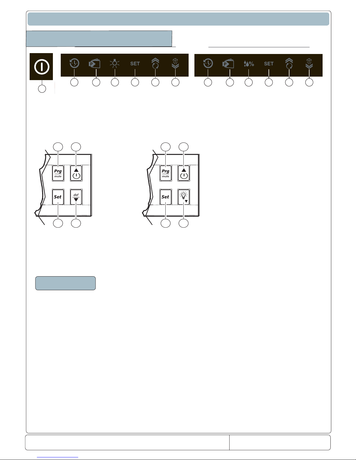
INSTRUMENT PROGRAMMING
Operation parameters, completely modiable from front keypad. Access to these is protected by a password that prevents random changes or modications by
unauthorised persons.
Accessing parameters (configuration):
1. press the PRG and SET buttons together for more than 5 seconds and the display will show "00", password required;
2. use the buttons or to scroll the numbers until displaying "11" (Password for accessing parameters);
3. conrming with SET, the rst modiable parameter will appear on the display.
Modifying parameters
After displaying the parameter, proceed as follows:
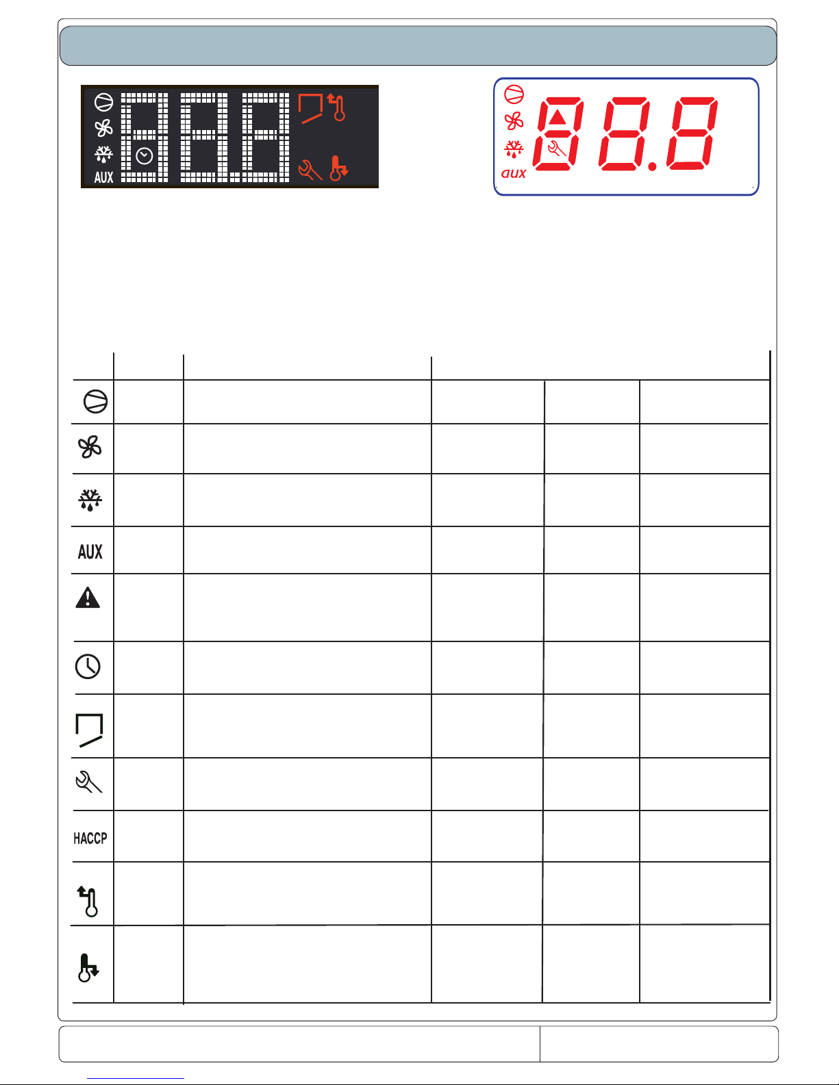
1. use the buttons or to scroll the parameters to the one to be modied. Scrolling is accompanied by lighting up of an icon on the display, representing the
parameter category. Alternatively, press the PRG button to display a menu of the categories or parameters for quickly accessing the family of parameters to be
changed;
2. scroll the menu with the buttons and and the codes of the various parameter categories (see "Summary of operation parameters") are displayed, together
with lighting up of the corresponding icon (if present);
3. on accessing the category, press SET to go straight to the rst parameter of the selected category (if no parameter is visible, pressing the SET button will
have no eect);
4. it is possible to continue consulting the parameters or return to the categories menu with the PRG button;
5. press SET to display the value associated with the parameter;
6. increase or decrease the value respectively with the buttons and ;
7. press SET to temporarily save the new value and return to the display of the parameter. Repeat the procedure from step 1 or step 2;
8. if the parameter has subparameters, press SET to display the rst subparameter;
9. press the buttons or to view all the subparameters;
10. press SET to display the associated value;
11. increase or decrease the value respectively with the buttons or ;
12. press SET to temporarily save the new value and return to the display of the subparameter code;
13. press PRG to return to the display of the parent parameter.
Saving new values assigned to parameters
To permanently save the values of the modied parameters, press the PRG button for more than 5 seconds, thus exiting the parameter modication proce-
dure. It is possible to cancel all the parameter modications, temporarily stored in RAM, and return to "normal operation" by not pressing any button for 60 seconds,
thus allowing the parameter modication session to expire forTIMEOUT.
Attention:If the modication session expires for timeout, the parameters will not be not restored.
If the power to the instrument is switched o before pressing the PRG button, all changes made to the parameters and temporarily saved will be lost.

Doc. No: 560001 EG
Page:5 Ed.1" 08-2014
From ser. no.:
Classification of parameters
As well as being divided according toTYPE, the parameters are grouped into logical CATEGORIES identied by the initial symbols or letters.
Given below are the existing categories with respective letters.
Parameters Category Text Icon
/Temperature probe management parameters Pro
rTemperature control parameters CtL
cCompressor safety time and activation parameters CMP
dDefrost management parameters dEF
AAlarm management parameters ALM
FFan management parameters fan
H General conguration parameters (addresses, enabling, etc.…) CnF
Default parameters
fotinUegnaRnoitpircseDenoizircseDretemaraP
1
/
/2
Stabilità misura 51...4ytilibatstnemerusaeM
2
/3
Rallentamento visualizzazione sonda 51...0esnopseryalpsideborP
3
/5
Selezione °C o°F galF1/0F°roC°noitceleS
4
/6
Punto decimale galF1/0tnioplamiceD
5
/tl
Visualizzazione su terminale interno 7…1lanimretnoyalpsiD
6
/A2
Configurazione sonda 2 4…02eborpnoitarugifnoC
7
/A3
Configurazione sonda 3 4…03eborpnoitarugifnoC
8
/c1
Calibrazione sonda CELLA 0.02..0.02-1eborpnoitarbilaC C/F (/10)
9
/c2
Calibrazione sonda 2 0.02..0.02-2eborpnoitarbilaC C/F (/10)
10
/c3
Calibrazione sonda 3 0.02..0.02-3eborpnoitarbilaC C/F (/10)
11
St
2r…1rtniopteStniopteS
C/
F
12
rd
Delta Regolatore 02…1.0atledlortnoC C/ F
13
r1
Set minimo ammesso 2r...05-dewollatnioptesmuminiM C/ F
14
r2
Set massimo ammesso 002…1rdewollatnioptesmumixaM C/ F
15
r5
Abilitazione monitoraggio temperatura 1...0gnirotinomerutarepmetelbanE C/ F
16
c0
Ritardo start compressore. ,ventole e aux zona neutra
all’accensione niM51...0norewopmorftuptuOyaleD
17
c1
Tempo minimo tra accensioni successive niM51…0norewopneewtebyaleD
18
c2
Tempo minimo di On del compressore niM51...0emitFFOrosserpmocmuminiM
19
c4
Duty setting niM001…0gnittesytuD
20
cc
Durata ciclo continuo sruoH51…0noitarudelcycsuounitnoC
21
c6
Esclusione allarme dopo ciclo continuo sruoH51…0elcycsuounitnocretfassapybmralA
PARAMETERS RELEVANT TO TEMPERATURE PROBE MANAGEMENT
PARAMETRI RELATIVI ALLA REGOLAZIONE DELLA TEMPERATURA\PARAMETERS RELEVANT TO TEMPERATURE CONTROL MANAGEMENT
PARAMETRI RELATIVI ALLA GESTIONE DEL COMPRESSORE\PARAMETERS RELEVANT TO COMPRESSOR MANAGEMENT

Doc. No.: 560001 EG
Page:6 Ed.1" 08-2014
From ser. no.:
22
d
d0
Tipo di defrost galF4...0tsorfedfoepyT
23
dI
Intervallo tra i defrost sruoH052…0stsorfedneewteblavretnI
24
dt1
Temperatura di fi ne defrost evap. End defrost temperature, evaporator -50…200 C/ F
25
dtP
002...0potstinutaerutarepmettsorfeddnEoppurgidatamrefaotnemanirbsenifidarutarepmeT C/ F
26
dP1
Durata massima defrost evaporatore Maximum defrost duration, evaporator 1…250 Min
27
d3
Ritardo inserimento defrost niM052...0yaledtratstsorfeD
28
d4
Abilitazione defrost allo start up galFy/npu-tratsnotsorfedelbanE
29
d5
Ritardo defrost allo start up niM052…0pu-tratsnoyaledtsorfeD
30
d6
Blocco display durante il defrost 2...0tsorfedgniruddlohnoyalpsiD
31
dd
Tempo di gocciolamento dopo il defrost niM51…0tsorfedretfaemitgnippirD
32
d8
Esclusione allarmi dopo il defrost sruoH51…0tsorfedretfassapybmralA
33
d8d
Esclusione allarmi dopo aperture porta niM/sruoH052…0mralagnineporoodnoyaleD
34
d9
Priorità defrost su protezioni compressore Defrost priority over compressor protectors n/y Flag
35
dC
Base dei tempi per defrost galF1/0)s/m=1;m/h=0(tsorfedesabemiT
36
dC1
Base dei tempi per allarmi galF1/0)s/m=1;m/h=0(smralaesabemiT
37
d10
Running time del compressore sruoH052...0tsorfedrofemitgninnurrosserpmoC
38
d11
0.02..0.02-tsorfedroferutarepmetemitgninnuRemitgninnuridarutarepmetidailgoS C/ F
39
dF0
Numero di ore del compressore attivo dopo il quale lo
sbrinamento deve essere attivato
NUM_COMP_ON number of hours the compressor is on
after which defrost must start 0...12 Hours
40
dF1
Numero di aperture porta dopo il quale il parametro DFO deve
decrementare
number of door openings after which dF0 must be
decreased 0...500 Units
41
dF2
Minuti da sottrarre al parametro DF0 per anticipare lo
sbrinamento
minutes to be subtracted to dF0 in order to anticipate
defrost 0...240 Min
42
A0
Differenziale allarmi e ventole 0.02…1.0laitnereffid)naf(mralA C/ F
43
A1
Tipo di soglia AL e AH galf1/0mralAetulosbAroevitaleR
44
AL
Soglia di allarme di bassa temperatura 002…05-dlohserhtmralaerutarepmetwoL C/ F
45
AH
Soglia di allarme di alta temperatura 002…05-dlohserhtmralaerutarepmethgiH C/ F
46
Ad
Ritardo segnalazione bassa e alta temperatura Low and high temperature signal delay 0…250 Min
47
A4
Confi gurazione ingresso digitale 1 galf51…0noitarugifnoc1tupnilatigiD
48
A5
Confi gurazione ingresso digitale 2 galF51…0noitarugifnoc2tupnilatigiD
49
A6
Blocco compressore da allarme esterno Stop compressor from external alarm 0…100 Min
50
A7
Ritardo rilevazione allarme esterno niM052…0yalednoitcetedmralalanretxE
51
A8
Abilitazione allarmi Ed1 ed Ed2 galF
0(off)-9(0n)
’2dE‘dna’1dE‘smralaelbanE
52
A9
Segnale virtuale 2( usato per connttere la almpada a led) Virtual input 2 configuration(Used in connection with
LED
_
Lam
p)
0…15 Flag
53
Ac
Allarme alta temperatura condensatore 002...0mralaerutarepmetresnednochgiH C/ F
54
AE
Differenziale allarme alta temperatura condensatore High condenser temperature alarm differential 0.1...20 C/ F
55
Acd
Ritardo allarme alta temperatura condensatore High condenser temperature alarm delay 0…250 Min
PARAMETRI RELATIVI ALLA GESTIONE DELLO SBRINAMENTO\PARAMETERS RELEVANT TO DEFROST MANAGEMENT
PARAMETRI RELATIVI ALLA GESTIONE DEGLI ALLARMI\PARAMETERS RELEVANT TO ALARM MANAGEMENT

Doc. No: 560001 EG
Page:7 Ed.1" 08-2014
From ser. no.:
56 A
ACS
002+....05-tniopteSnaelCmralAnaelCemrallareperutarepmetidailgoS C/ F
57
ACd
Ritardo allarme alta temperatura condensatore Alarm Clean differential C/ F
58
F0
Gestione ventilatori galF3...0tnemeganamnaF
59
F1
Temperatura accensione ventilatore 002...05-erutarepmetpotsnaF C/ F
60
F2
Ventilatore off con compressore off galF1/0FFOrosserpmochtiwFFOnaF
61
F3
Ventilatore in sbrinamento galF1/0tsorfednisnaF
62
Fd
niM51…0gnippirdretfaFFOnaFotnemaloiccogsolopodotnepserotalitneV
63
F10
2...0LVL_ytidimuHàtidimU
64
F11
ces006..0edomytidimuhwolniemitNOnaFàtidimuassabnioseccaerotalitneV
65
F12
ces006..0edomytidimuhwolniemitFFOnaFàtidimuassabniotnepserotalitneV
66
F13
ces006..0edomytidimuhmuidemniemitNOnaFàtidimuaidemnioseccaerotalitneV
67
F14
ces006..0edomytidimuhmuidemniemitFFOnaFàtidimuaidemniotnepserotalitneV
68
F15
ces006..0edomytidimuhhgihniemitNOnaFàtidimuatlanioseccaerotalitneV
69
F16
ces006..0edomytidimuhhgihniemitFFOnaFàtidimuatlaniotnepserotalitneV
70
F17
Differenziale del compressore in accensione con umidita bassa temperature differential for compressor ON in low hum. 0,1..20 sec
71
F18
Differenziale del compressore in accensione con umidita media temperature differential for compressor ON in medium
hum. 0,1..20 sec
72
F19
Differenziale del compressore in accensione con umidita alta temperature differential for compressor ON in high hum. 0,1..20 sec
73
H0
702…0sserddaeciveDovitisopsidozziridnI
4yalerfonoitcnuF4elerledotnemanoiznuF
)41=evlavortcele
wolF()41=alovlavortteleossulF(
)51=ecnatsiseremarF()51=ecinocaznetsiseR(
)8=thgilroodssal
G()8=ortevatropecuL(
)2=ecnatsiserepipniarD()2=asnednocociracsidaznetsiseR(
75
H2
galF6...0)6=N;1=Y(FFO/NOelbanE)6=N;1=Y(FFO/NOotsatatilibasid/atilibA
76
H4
galF1/0rezzubelbasiDonilaciCatilibasiD
77
H6
552...0dapyekkcoLareitsatoccolB
78
H7
Percentuale di umidità (H7=0 , disabilita controllo umidità F0=3)-
Attivazione Luce (H7=1) -Tipo di controllo : Versione Mass ( H7=2)
keyboard type: HUM% key (H7 = 0, enable humidity
management with F0=3) or LIGHT key (H7 = 1).
Controller t
yp
e: Mass version
(
H7 = 2
)
1...3
79
CCd
syaD999.......0syaDretnuoCnaelCaizilupidinoigoiggetnoC
80
Cd
syaD999.......0syadnaelCaizilupidinroiG
81
SAn
galF552.......0rebmunsmralAecivreSitunevvaecivreSopitidimrallaoremuN
82
SAr
galF1.......0naSteserretnuocsmralAecivreSsmralAecivreSiederotatnocledotnemarezzA
83
CAn
galF552.......0retnuocmralAnaelCteseromitlu’lladitunevvanaelCimrallaidoremuN
84
CAr
galF1.......0teserretnuocmralAnaelCnaelCidimrallailgederotatnocledotnemarezzA
85
4r1
Spazio tra il differnziale corrente e il flusso della temperatura della
elettrovalvola
Gap between current differential and flow electro-valve
tem
p
erature differential 0,1..20 C/ F
86
4r2
Abilita/disabilita la resistenza cornice mobile con la referenza
della tem
p
eratura im
p
ostata
Parameter (temperature) enabling/disabling frame
resistance with reference to chosen cell set
p
oint -20..20 C/ F
87
4r3
Ritardo per la resistenza di scarico( il tempo deve includere la
durata del defrost
)
Delay for drain pipe switch-off (the value must include the
defrost duration
)
0...60 min
74
PARAMETRI GENERALI DI CONFIGURAZIONE
PARAMETRI RELATIVI ALLA GESTIONE DEL VENTILATORE EVAPORATORE\PARAMETERS RELEVANT TO EVAPORATOR FAN MANAGEMENT
H1
0...16 Flag

Doc. No.: 560001 EG
Page:8 Ed.1" 08-2014
From ser. no.:
In case of faulty thermostatting probe, the display shows the messa-
ge rE alternating with E0 (compartment probe S1). The appliance still
works and compressor activation and/or deactivation is time mana-
ged (15 min. ON and 15 min. OFF). The alarm condition is automati-
cally reset as soon as compartment probe operation is restored.
In case of faulty room probe, the display shows the message E1 (room
probe S2). The alarm condition is automatically reset as soon as com-
partment probe operation is restored.
The service alarm signalling icon flashes whereas the controller buzzer
is deactivated
The service alarm signalling icon flashes whereas the controller buz-
zer is deactivated. In case of faulty condenser probe (if installed on
the machine), the display alternately shows the message SEr/E2. The
alarm condition is automatically reset as soon as compartment probe
operation is restored.
Clean alarm: when the condenser is very dirty on the display will
appear the label CLn; this alarm dosen’t stop the cycle but only
advises the customer to clean the condenser. The CLn alarm
appears only after 90 days to work of compressor and when the
temperature of the condenser and ambient is over to delta of the
parameter ACS
The alarm disapears when the temperature decrease from parameter
ACd.( differential) or pressing the button Prg.
With the LED lamp disconnected, the display will show the message
ce in sequence of temperature.
This happens when the lamp is disconnected or damaged.
In case of no lamp connection, the controller does not diagnose any fault.
The alarm disappears when the lamp is reconnected.
Parameter to be configured for lamp A9=9
THERMOSTATTING PRO-
BE FAULT ALARM
ROOM PROBE
FAULT ALARM
CONDENSER PROBE
FAULT ALARM (IF PRESENT)
CLEAN ALARM (ACTIVA-
TABLE IF CONDENSER PRO-
BE IS PRESENT)
LED LIGHT CE ALARM
(in Premium models only)
SERVICE ALARMS AND SIGNALLING
SERVICE ALARMS
ALL THE SERVICE ALARMS GENERATED FOR APPLIANCE FAULTS ARE SIGNALLED ON THE DISPLAY THROUGH
THE ASSISTANCE REQUEST ICON
E0
rE
E1
E2
CLn
00cn

Doc. No: 560001 EG
Page:9 Ed.1" 08-2014
From ser. no.:
To manually activate a defrost cycle it is necessary to keep the tem-
perature decrease button pressed for at least 3 seconds.
The display shows the message dFb/defrost start for a few seconds
and the icon signalling activation of the defrost cycle lights up.
Defrost can be manually stopped by pressing the DEF/decrease tem-
perature button again for at least 3 seconds. The display shows the
message dFE/defrost end.
Defrost in the range models is carried out following the algorithm va-
lues: 1) parameter dF0, associating the actual hours of compressor
operation, 2) parameter dF1, number of door openings, where para-
meter dF0 must be reduced ,3)parameter dF2, minutes to be add to
parameter dF1 from subtracted to parameter dF0,to anticipate defrost .
Parameter dl remains active if these values are not respected.
In case of activation of continuous cycle, by pressing the temperature
decrease button for more than 5 seconds the display will show the
message ccb, at the same time as the temperature the message tc
will appear, meaning that “turbo cooling” has been activated. The cycle
will end for time, by parameter CC, or for temperature by parameter
AL, or by pressing the button again.
The humidity value is activated by pressing the corresponding button.
Three modes can be activated: low, medium, high % .F0= 3
The function activates the evaporator fans following the logic of low,
medium and high humidity % to be obtained in the compartment.
The parameters functioning in this are:
MANUAL DEFROST
ACTIVATION OF “TURBO CO-
OLING” CONTINUOUS CYCLE
ccb
ACTIVATION OF HUMIDITY
CYCLE
SERVICE ALARMS AND SIGNALLING
DFb
dFE
ccE
tC
Selection Correspondence
Low humidity
Medium humidity
High humidity
Fans always ON
Fans always ON
Fans always ON
F11= Fans ON
F12= Fans Off
F13= Fans ON
F14= Fans Off
F15= Fans ON
F16= Fans Off
Compressor OFF Compressor ON
Evaporator fans functionality

Doc. No.: 560001 EG
Page:10 Ed.1" 08-2014
From ser. no.:
dor
When the time set on parameter d8d is expired, the alarm dor
appear on the display, following from buzzer signaling and the red
light on blinking , (premium model only).
The alarm disappear when the door is closed.
The buzzer is off pressing the icon on display.
If the alarm is On with the door closed, this is due to :
- door not aligned
- control panel not aligned
- sensor broken
The calibration of infrared sensor is of 9 mm: over this distance
the sensor not more close the contact and the alarm will be al-
ways present.
0
0
EE
0
EF
When one of the other alarms apper on the display , check the
parameter list.
If the parameters setted are not kept in memory replace the
instrument.
EPROM ALARM
SERVICE ALARMS AND SIGNALLING
HI
LO
TEMPERATURE ALARM
TEMPERATURE ALARM
"SER"
SEr
The icon light up and audible alarm sound when the compartement
temperature exceeds the set maximun value. The alarm ceases
when the temperature returns to Set point.
A Parameter AL and AH determine the threshold of alarm of hight
or lower temperature.
Another parameter as Ad determine the delay of alarm .
When the temperature return to set point, and the icon stay again
ON , press the button PRG or directly on icon.
When the temperature of condenser is over of delta parameter AC
with a delay time to Acd , the alarm “SEr” appears on the display
and the compressor if stopped.
The alarm can be resetted pressing togheter the buttons PRG
and UP and the delay Acd will be re setted. The compressor will
be ON only if the temperature reaches the value of AC-AE and the
time of value ( C1 ( compressor delay at power on) will expired. If
the alarm “Ser” appears again check if the condenser fan works or
not.
DOOR OPEN

Doc. No: 560001 EG
Page:11 Ed.1" 08-2014
From ser. no.:
Algoritmo defrost/defrost algorithm Ecostore ONLY
Defrost
Defrost management has in principle the same features of the current FW: however, as the evaporator probe is
not present, defrost will be managed by counting working hours of the compressor and will end for timeout.
A programmed defrost will be done every defined number (parameter dF0) of working hours.
In addition, the algorithm will count the number of openings of the door as well. The aim is to anticipate of a
number of minutes (dF2) the programmed defrost with reference to the total number of openings of the door.
Every time the programmed defrost is done, the total on-time hours of compressor and the number of door
openings will be reset. Proper parameters will be employed in order to manage this algorithm.
In order to do this, consider flux diagram of Figure 3.4. For instance, t_on_cmpr is the variable counting on-time
hours of compressor starting from last defrost, whereas n_open_door is the number of openings of the door.
t_on_cmpr is reset after each defrost, while n_open_door is reset every time it reaches dF1 value.
Figure 3.4: ux diagram for defrost algorithm.
START
t_on_cmpr
≥
defrost_cycle
do defrost
t_on_cmpr = 0
n_open_door = 0
END
n_open_door
≥
dF1
defrost_cycle = defrost_cycle - dF2
n_open_door = 0
?
YES
N
O
N
O
YES
?
defrost_cycle = dF0

Doc. No.: 560001 EG
Page:12 Ed.1" 08-2014
From ser. no.:
Main termoregulator and where used
Factory code 646R10802
SPC = 093328
used on Mass and Gab freezer and refrigerated
3 relay ( 8A -8A-5A)
Factory code 646R11001
SPC = 093329
used on Mass and Gab glass door freezer and refrige-
rated
4 relay ( 16A -8A-8A-8A)
Factory code 646R11101
SPC = 093434
used on Mass dual temp MASTER freezer and refrige-
rated
4 relay ( 16A-8A -8A-8A)
Factory code 646R11301
SPC = 093438
used on Mass dual temp SLAVE freezer and refrigera-
ted
4 relay ( 16A-8A -8A-8A)
Factory code 646R10602
SPC = 093437
used on Premium all and as Master on dual tempera-
ture
4 relay ( 16A-8A -8A-8A)

Doc. No: 560001 EG
Page:13 Ed.1" 08-2014
From ser. no.:
Factory code 646R11401
SPC = 093439
used on Premium as Slave on dual temperature
4 relay ( 16A-8A -8A-8A)
Factory code 648R05000
SPC = 093389
used on Premium dual doors
and Super premium
Factory code 648R05500
SPC = 093388
used on Premium one doors
and half doors
Power Termoregulator

Doc. No: 560001 EG
Page:14 Ed.1" 08-2014
From ser. no.:
Factory code 646R11500
SPC = 0TH303
used on all Cabinets and couters all
range asia sb line with power supply to
12V

Doc. No.: 560001 EG
Page:15 Ed.1" 08-2014
From ser. no.:
ENGLISH
7.1 Temperature probe management parameters
Code Parameter Models UOM Type Min Max Def.
Pw Password MSYF - C 0 200 22
/2 Measurement stability MSYF - C 1 15 4
/3 Probe display response MSYF - C 0 15 0
/4 Virtual probe MSYF - C 0 100 0
/5 Select °C or °F MSYF ag C 0 1 0
/6 Decimal point MSYF ag C 0 1 0
/tI Display on internal terminal MSYF - C 1 7 1
/tE Display on external terminal MSYF - C 0 6 0
/P Select type of probe MSYF - C 0 2 0
/A2 Conguration of probe 2 (S2) YF - C 0 4 2
MS - C 0 4 0
/A3 Conguration of probe 3 (S3, DI 1) MSYF - C 0 4 0
/A4 Conguration of probe 4 (S4, DI 2) MSYF - C 0 4 0
/A5 Conguration of probe 5 (S5, DI 3) MSYF - C 0 4 0
/c1 Calibration of probe 1 MSYF °C/°F C -20 20 0.0
/c2 Calibration of probe 2 MSYF °C/°F C -20 20 0.0
/c3 Calibration of probe 3 MSYF °C/°F C -20 20 0.0
/c4 Calibration of probe 4 MSYF °C/°F C -20 20 0.0
/c5 Calibration of probe 5 MSYF °C/°F C -20 20 0.0
Tab. 7.a
Note: par. /A5 and /c5 refer to instruments with 5 relays (ir33DIN, powercompact and MasterCella).
‘/2’: Measurement stability
Denes the coecient used to stabilise the temperature reading. Low values assigned to this parameter allow a prompt response of
thesensortotemperaturevariations,butthereadingbecomesmoresensitivetodisturbance.Highvaluesslowdowntheresponse,but
guarantee greater immunity to disturbance, that is, a more stable and more precise reading.The parameter acts on the temperature
readings, ltering the minimum variations, and at the same time considers the average of the readings. Default:‘/2’=4.
/3: Probe display response
Thisparameterisused toset theupdaterate forthe temperaturedisplay.Thetemperatureshown onthe displaytends tofollowrapid
deviations away from the set point very slowly, and vice-versa, moves very quickly in the event where the temperature displayed is
nearingthesetpoint.Ifthecontroltemperatureexceedsthehighorlowtemperaturethresholds(andanALorAHalarmisactivated),or
ifthemaximumnumberoflteringsteps (255)isexceeded(seetheTimeoutcolumninTable 7.b),thelteringwouldimmediatelybe
bypassedand thetemperaturedisplayedwould bethetemperatureeectivelymeasured,untilall thealarmsarereset.Theparameter
only aects the temperature displayed, and not the temperature used for the control functions.
Important:
• the control temperature actually measured diers from the value displayed, and therefore the outputs may not be activated with
reference to the latter temperature value.
• if the probe displayed is a product probe, with temperature values higher than the set point, the probe display rate algorithm will
be faster for decreases in the temperature and slower for increases;
• if the probe displayed is an evaporator or condenser probe, the display rate algorithm always refers to the set point and thus may
have specic eects (fast when the evap. probe reading increases and slow when it decreases; fast when the condenser probe
reading decreases and slow when it increases);
• the parameter /3 acts on the temperature displayed by the instrument, if /tE=0 (no probe displayed by the repeater display); if
the repeater display is congured (/tE <> 0), the parameter /3 will act on the temperature displayed by the repeater.
Example: in the case of“bottle coolers”, typically used in supermarkets, when the doors are opened frequently, due to the greater
thermalinertia ofthe liquidscomparedtothe air(andthefact thattheprobeis positionedin theairandnotdirectly ontheproducts),
theinstrumentmeasuresatemperaturethatishigherthaneectivetemperatureofthesoftdrinks,thusdisplayingaquite“unrealistic”
temperature. Setting the parameter /3 to a value other than 0, any abrupt variations in temperature are“ltered”on the display,
showing a temperature trend that is“closer”to the actual trend of the product temperature.The following table shows the possible
values of‘/3’and the corresponding display delayed update values (Tdel).
Value of par. /3 Display delay (Tdel) Timeout
0 Disabled 0
1 5 s 21 min
2 10 s 42 min
3 15 s 64 min
4 20 s 85 min
5 25 s 106 min
6 30 s 127 min
7 40 s 170 min
8 50 s 212 min
9 60 s 255 min
10 75 s 319 min
11 90 s 382 min
12 105 s 446 min
13 120 s 510 min
14 150 s 637 min
15 180 s 765 min
Tab. 7.b
Default:‘/3’=0 => Function disabled.
/4: Probe average (virtual probe)
This parameter is used to choose whether to control the temperature based solely on the room probe reading, or alternatively
whether to refer to the“weighted”average of the room probe S1 and probe 2 (S2, see the parameter‘/A2’). This parameter is
useful in special applications.
7. DESCRIPTION OF THE OPERATING PARAMETERS

Doc. No.: 560001 EG
Page:16 Ed.1" 08-2014
From ser. no.:
ENGLISH
Example: if the room probe is in intake mode, and probe 2 in outlet mode, control can be performed based on the weighted
average of the 2 values read.
The formula used is: probe average (Virtual probe) = [S1 x (100 - P) + (S2 x P)] / 100 where:
S1 = room probe; S2 = probe 2; P = value of the parameter /4.
Virtual probe:
• /4=0 control is performed using the room probe - this is the typical situation;
• /4=100 control is performed in reference to the values read by probe 2;
• /4=50 control refers to a“virtual”probe, calculated based on the average between the room probe and probe 2.With values
above 50, probe 2 has a greater weight in the calculation, vice-versa for values below 50.
Important: in the event of faults or if probe 2 is not enabled, the instrument uses the room probe only. If the fault is on the room
probe, the“Control probe”error is signalled.
Default: /4=0 => control on room probe.
/5: Select °C or °F
Denes the unit of measure (degrees Centigrade or degrees Fahrenheit) shown on the display.
/5=0 to operate in degrees Centigrade.
/5=1 to operate in degrees Fahrenheit.
Default: /5=0 => operation in degrees centigrade.
/6: Decimal point
Used to enable or disable the display of the temperature with resolution to the tenth of a degree between -20 and + 20.
Note: the exclusion of the decimal point is active only with reference to the display of the reading on the main and remote
displays, while the parameters are always set to the tenth of a degree.
‘/6’=0 the readings are displayed to the tenth of a degree, between -20 and +20 °C;
‘/6’=1 all the readings are displayed without the tenths of a degree.
Default: /6 = 0 = > decimal point displayed.
/tI: Probe displayed on instrument
For selecting the probe to be displayed by the instrument.
/tI=1 => virtual probe
/tI=2 => probe 1
/tI=3 => probe 2
/tI=4 => probe 3
/tI=5 => probe 4
/tI=6 => probe 5
/tI=7 => set point
Note:
• control is always based on the virtual control probe;
• if the probe to be displayed has not been enabled, the display will show the message ‘___’.
Default: /tI=1 =>Virtual probe.
/tE: Probe displayed on external terminal
Selects the probe to be displayed on the remote terminal.
/tE=0 => remote terminal not present
/tE=1 => virtual probe;
/tE=2 => probe 1;
/tE=3 => probe 2;
/tE=4 => probe 3;
/tE=5 => probe 4;
/tE=6 => probe 5.
Important:
Control is always based on the virtual control probe;
If the probe to be displayed has not been enabled, the display will show the message‘___’;
If the probe to be displayed is faulty, the display will show the message‘___’;
If the terminal is not present, the display will remain completely dark.
Default: /tE=0 => Remote terminal not present.
/P: Select type of probe
Used to select the type of probe used for the measurements.
/P=0 => NTC standard with range -50T90 °C
/P=1 => NTC with extended range -40T150 °C
/P=2 => PTC standard with range -50T150°C
For correct readings from the PTC probes, the hardware must be prepared to accept PTC readings (as well as NTC).
Note: all models in the ir33 range manage NTC probes with extended range (models HT).
Default:‘/P’=0 => NTC standard with range -50T90 °C
Available on all models tted with NTC inputs.

Doc. No.: 560001 EG
Page:17 Ed.1" 08-2014
From ser. no.:
rd
Set Point
OFF
ON
DIRECT Freddo
attuatore
D
St
rd/2 rd/2
Sonda virtuale
Direct
ENGLISH
Fig. 7.b
Fig. 7.a
/A2: Conguration of probe 2
Used to congure the operating mode of probe 2.
/A2= 0 => probe 2 absent
/A2= 1 => product probe (used for display only)
/A2= 2 => defrost probe
/A2= 3 => condenser probe
/A2 = 4 => antifreeze probe
In any case, probe 2 is used for calculating the virtual control probe.
Default: /A2= 2 => defrost probe; /A2= 0 on models M and S => probe 2 absent.
/A3: Conguration of probe 3
As above, but relating to probe 3.
Important note: the input is enabled for use with a probe only if the parameter corresponding to digital input A4 is set to 0.
Default: /A3= 0 => Probe 3/Digital input absent.
/C1: Calibration or oset for probe 1
/C2: Calibration or oset for probe 2
/C3: Calibration or oset for probe 3
These parameters are used to correct the temperature measured by the probes, using an oset: the value assigned to these
parameters is in fact added to (positive value) or subtracted from (negative value) the temperature measured by the probes.The
temperature value is corrected by the oset before checking if the reading is out-of-range.
Example: to decrease the temperature measured by probe 1 by 2.3 degrees, set /C1= -2.3.The calibration or oset can be set
from -20 to +20.
Warning: if the probe is disabled, the display shows‘___’. If the probe is faulty, the display shows the corresponding error code.
When displaying the parameter, pressing SET shows the value of the corresponding probe already corrected with the oset, while
pressing SET a second time displays the abbreviated code.
Default: /C1=/C2=/C3=/C4=/C5=0 no oset.
7.2 Temperature control parameters
Code Parameter Model UOM Type Min Max Def.
St Temperature set point MSYF °C/°F F r1 r2 0.0
rd Control delta -SYF °C/°F F 0.1 20 2.0
rn Dead band -SYF °C/°F C 0.0 60 4.0
rr Reverse dierential for control with dead band -SYF °C/°F C 0.1 20 2.0
r1 Minimum set point allowed MSYF °C/°F C -50 r2 -50
r2 Maximum set point allowed MSYF °C/°F C r1 200 60
r3 Operating mode -SYF ag C 0 2 0
r4 Automatic night-time set point variation MSYF °C/°F C -20 20 3.0
r5 Enable temperature monitoring MSYF ag C 0 1 0
rt Temperature monitoring interval MSYF hours F 0 999 -
rH Maximum temperature read MSYF °C/°F F - - -
rL Minimum temperature read MSYF °C/°F F - -
Tab. 7.c
St: set point
Establishes the set point value used by the controller. Default: St=0.0.
rd: Control delta
Establishes the value of the dierential, or hysteresis, used for temperature control. Low values guarantee an ambient temperature
that deviates only slightly from the set point, but involves frequent starts and stops of the main actuator (normally the compressor).
In any case, the compressor can be protected by suitably setting the parameters that limit the number of
activations/hour and the minimum OFF time (see the C parameters).
Note: if control with two compressor steps has been selected (‘H1, H5’=12, 13), the dierential‘rd’is divided between the two
steps.
Default: rd =2
rn: Dead band
Establishes the value of the dead band, when the auxiliary output is selected as heating, in control with dead band mode.The
dierential is in the centre of the dead band.

Doc. No.: 560001 EG
Page:18 Ed.1" 08-2014
From ser. no.:
rd
OFF
ON
REVERSE Caldo
attuatore
R
St
rd/2 rd/2
Sonda
virtuale
Reverse
Fig. 7.c
ENGLISH
Note:
• the step associated with the aux 1 or 2 output is only associated with the protection timer c0, while the step associated with the
compressor (in both direct and reverse operation) is associated with the timers c0, c1, c2, c3. As a result, the steps may be active
at the same time due to the protectors associated with the compressor step (minimum on time), as well as the unit defrost
status;
• if the curtain switch function is enabled (‘A4, A5, A9’=7), the controller modies the set point when the contact closes, adding
or subtracting the value of parameter‘r4’; the new value is used for all functions relating to the set point (e.g. relative high and
low temperature alarms, dead band, etc.).When‘r4’=3.0 (preset value) the set point is increased by 3 degrees compared to the
value used with the curtain open.
Default:‘rn’=4.
rr: Reverse dierential for control with dead band
Establishes the value of the dierential used in reverse temperature control, when the auxiliary output is selected as heating, in
control with dead band mode. Default:‘rr’=2.
Note: no protection times are featured for the reverse output.
r1: minimum set point allowed
Determines the minimum value that can be set for the set point. Using this parameter prevents the user from setting a set point
lower than the value indicated by r1. Default: r1=-50.
r2: maximum set point allowed
Determines the maximum value that can be set for the set point. Using this parameter prevents the user from setting a set point
higher than the value indicated by r2. Default: r2 = +60.
r3: operating mode
ir33 can work as a thermostat and defrost controller for static units at normal temperature (r3=0), as a simple thermostat in Direct
operation (r3=1), or as simple thermostat in Reverse-cycle operation (r3=2).
r3=0 Direct thermostat with defrost control (cooling);
r3=1 Direct thermostat (cooling);
r3=2 Reverse-cycle thermostat (heating).
Also see the description of parameters A4, A5, A9.
Note: with r3=1 and r3=2, the defrosts are always disabled.
A digital input set for direct/reverse-cycle control with parameter r3 has priority over the operating mode.The gure to the side
shows reverse control with two compressor steps.
Default: r3=0=> Direct thermostat operation with defrost control.
r4:Automatic variation of the set point in night-time operation
This parameter is part of the group for control of the curtain switch, together with A4, A5 and A9,
programmable for conguring the digital inputs.When the curtain is closed, and consequently, the digital input connected to the
curtain switch is closed, the controller automatically increases the set point by the value assigned to r4 in direct mode (cooling),
and automatically decreases the set point by the value assigned to r4, in reverse mode (heating).
Important: if the value of r4 is negative, the controller with the curtain switch closed will decrease the set point, in direct mode
(cooling), and increase the set point in reverse mode (heating).
Default: r4=3.0..
r5: Enable minimum and maximum temperature monitoring.
r5=0 disabled
r5=1 enabled
Default: r5=0
rt: Eective interval for monitoring the maximum and minimum temperature.
rH: Maximum temperature measured in the interval rt.
rL: Minimum temperature measured in the interval rt
All these parameters are used by the instruments to record the minimum and maximum temperature measured by the room
probe in a period of up to 999 hours (over 41 days).To enable this function, proceed as follows:
• set r5=1; select rt;
• press SET to display for how many hours the minimum and maximum temperature have been recorded (if the function has just
been enabled, rt=0);
• to start recording the temperatures again, press q for more than 5 seconds when displaying the hours (the message rES
indicates that the value has been reset).
The instrument resets the number of hours and restarts the monitoring process;
• to display the maximum temperature measured by the probe, read the value associated with rH, while to display the minimum
temperature measured by the probe, read the value associated with rL..
Important:
• after the maximum time of 999 hours, the monitoring of the minimum and maximum temperature continues, while the time
value remains xed at 999.

Doc. No.: 560001 EG
Page:19 Ed.1" 08-2014
From ser. no.:
accensione strumento
power ON
ON
ON
OFF
ON
OFF
OFF
C0
richiesta di intervento
insertion request
compressore
compressors
ON
ON
OFF
OFF
C1
richiesta inserimento
insertion request
compressore
compressors
ON
ON
OFF
OFF
C2
richiesta inserimento
insertion request
compressore
compressors
ON
ON
OFF
OFF
C3
richiesta inserimento
insertion request
compressore
compressors
ON
OFF
C4
compressore
compressors
OFF = 15 min.
Fig. 7.d
Fig. 7.e
Fig. 7.f
Fig. 7.g
Fig. 7.h
ENGLISH
7.3 Compressor management parameters
Code Parametro Models U.M. Type Min Max Def.
c0 Compressor, fan and AUX start delay on power up in dead zone -SYF min C 0 15 0
c1 Minimum time between successive starts -SYF min C 0 15 0
c2 Minimum compressor OFF time -SYF min C 0 15 0
c3 Minimum compressor ON time -SYF min C 0 15 0
c4 Duty setting -SYF min C 0 100 0
cc Continuous cycle duration -SYF hours C 0 15 0
c6 Alarm bypass after continuous cycle -SYF h/min C 0 250 2
c7 Maximum pump down time -SYF s C 0 900 0
c8 Comp. start delay after open PD valve -SYF s C 0 60 5
c9 Enable autostart function in PD -SYF ag C 0 1 0
c10 Select pump down by time or pressure -SYF ag C 0 1 0
c11 Second compressor delay -SYF s C 0 250 4
Tab. 7.d
c0: Compressor and fan start delay (if‘FAN’relay present) on start-up
When the controller is switched on, the compressor and the evaporator fans and the auxiliary relay in control with dead band (H1 or
H5=11) start after a delay (in minutes) equal to the value set for this parameter, in order to protect the compressor against repeated
power-ups in the event of frequent power drops. Default: c0=0 => no minimum delay is set.
Example: setting c0=6 forces the compressor to wait 6 minutes before starting from when power returns. In the event of systems
with more than one compressor, the parameter c0 can also be used to avoid simultaneous starts of a series of units. Simply set
a dierent value of c0 for each compressor. Note: the second compressor step, for the aux 1 or 2 output (‘H1 or H5’=12, 13), is
associated with the timers‘c0’,‘c1’,‘c2’,‘c3’.
c1: Minimum time between two successive starts of the compressor
Sets the minimum time (in minutes) that must elapse between two starts of the compressor, irrespective of the temperature and the
set point. Setting this parameter limits the number of starts per hour.
Default: c’=0 => no minimum time is set between two starts.
Example: if the maximum number of activations/hour allowed is 10, simply set c1=6 to ensure that this limit is respected. Note:
the second compressor step, for the aux 1 or 2 output (‘H1 or H5’=12, 13), is associated with the timers‘c0’,‘c1’,‘c2’,‘c3’.
c2: Minimum compressor OFF time
SSets the minimum time (in minutes) for the compressor to remain OFF. The compressor is not started again until the minimum
time selected (c2) has elapsed from when it last stopped.
Note: this parameter is useful to ensure the balancing of the pressure after the compressor stops for systems with hermetic and
capillary compressors.The second compressor step, for the aux 1 or 2 output (‘H1 or H5’=12, 13), is associated with the timers
‘c0’,‘c1’,‘c2’,‘c3’.
c3: Minimum compressor ON time
Sets the minimum running time for the compressor.The compressor is not stopped until it has been ON for at least the minimum
time selected (c3). Note: the second compressor step, for the aux 1 or 2 output (‘H1 or H5’=12, 13), is associated with the timers
‘c0’,‘c1’,‘c2’,‘c3’.
Default: c3=0 => no minimum running time is set.
c4: Duty setting
If the virtual control probe fault alarm occurs (see parameter‘/4’), this parameter is used to ensure the operation of the compres-
sor until the fault is resolved.
Default: c4=0 => compressor always O in the event of a virtual control probe error.
Important: In the event of errors on probe 2, the virtual probe corresponds to the room probe (probe 1) and consequently the
Duty Setting is not activated.
In practice, as the compressor is no longer able to operate based according to the temperature (due to the probe fault), it is made
to run cyclically with an operating time (ON time) equal to the value assigned to parameter c4 (in minutes) and a xed OFF time
of 15 minutes.
There are two values of c4 that cause special behaviour:
c4=0, in the event of faults involving the virtual control probe, the compressor is always OFF;
c4=100, the compressor is always ON, that is, the 15 minute OFF time is always ignored.
Special situations:
• if the virtual control probe error occurs while the compressor is OFF, it remains OFF for 15 minutes, and is then started
(respecting the times set for parameters c1 and c2) and remains ON for a time equal to c4, Duty Setting.This special operation is
signalled by the LED that ashes during the compressor OFF period, and remains on steady when the compressor is operating.
The fans continue to operate according the set parameters (see F parameters). If the duty setting requires the immediate shut-
down of the compressor for a non-specied time (c4= 0), this is done without observing the compressor protection times.
• if the virtual control probe error occurs while the compressor is ON, it remains ON for the time c4, and then is stopped (without
observing the minimum ON time, if set for parameter c3) and remains OFF for 15 minutes (the LED ashes in this phase).
After this, cyclical operation starts, with an operating time equal to the value of c4.
Warning: If the virtual probe error disappears, the unit returns to normal operation.
Note: if control with two compressor steps is selected (with or without rotation,‘H1 or H5’= 12 or 13), the duty setting acts on
both steps.

Doc. No.: 560001 EG
Page:20 Ed.1" 08-2014
From ser. no.:
ENGLISH
cc: Continuous cycle duration
This is the time (in hours) during which the compressor operates continuously to lower the temperature, even below the set point.
With cc=0 => the continuous cycle is disabled.The controller exits the continuous cycle procedure after the time set for parame-
ter cc has elapsed, or upon reaching the minimum specied temperature (see the minimum temperature alarm, parameter AL).
Default: cc=0 (hours).
Note: if control with two compressor steps is selected (with or without rotation,‘H1 or H5’= 12 or 13), the continuous cycle acts
on both steps
c6: Alarm bypass after continuous cycle
This is the time (in hours or minutes) for which the temperature alarm is deactivated after a continuous cycle. If the temperature
of the refrigeration unit, after the continuous cycle, falls due by inertia below the minimum temperature (set point – AL), the
activation of the low temp. alarm is delayed for the time c6.
Default: c6=2 (hours).
Warning: remember that at the minimum specied temperature (see the minimum temperature alarm, parameter AL) the
continuous cycle is forced OFF and deactivated.
Parameter‘c6’may be expressed in hours‘dC1’= 0’(default) or minutes‘dC1’=1’.
c7: Maximum pump down time
This parameter determines, depending on the setting of parameter c10, the maximum time in minutes by which the circuit must
reach the required low pressure value in pump down operation (c10=0), or the compressor operating time after the closing of the
pump down valve in case of pump down operation by time (c10=1).The pump down valve must be connected to the auxiliary
output, setting the relevant parameter (H1 or H5).
Pump down by pressure (c10=1):
When reaching the maximum pump down time, the compressor stops and the Pd alarm is activated, which disables the compressor
autostart function (see parameter c9) with the pump down valve closed, on the“high pressure”request from the pressure switch.
The compressor remains OFF until the controller requires cooling.When reaching the set point, a pump down procedure is run and
the alarm is
automatically reset if the low pressure is reached within the time c7.
Low pressure is monitored by connecting the low pressure switch to one of the two digital inputs and setting the parameter A4, A5
or A9.
Pump down by time (c10=1):
When the compressor operating time c7 is reached after the closing of the valve, the compressor is stopped, irrespective of the low
pressure reading, and the Pd alarm is deactivated. In any case, the compressor is stopped when reaching the low pressure.
In this case, autostart in pump down is disabled. Default: c7 =0 => pump down disabled.
c8 : Compressor start delay after opening of PD valve
This parameter determines after how many seconds from the opening of the pump down valve the compressor starts. It is useful
to avoid activating the LP alarm unnecessarily.
The low pressure alarm (LP), with valve open and compressor ON, is activated by the opening of the pressure switch.This alarm
stops the compressor and is reset automatically.
Starting from July 2007 parameter c8 has been set to 0 and is not visible in the controllers distributed.The function relating to c8
can still be used, however it must be stressed that in certain conditions, during the time c8 (alarm from digital input, probe alarm,
on/o), the pump down valve may remain open.
c9: Enable autostart function with PD operation (active when C7=6)
If parameter c9 is set to 0, the system will perform a pump down cycle each time the pump down valve closes. If the parameter
is set to 1, on the other hand, the system will perform a pump down cycle each time the pump down valve closes and on each
successive request from the low pressure switch when there is no cooling requirement (autostart situation).The activation of a
compressor autostart cycle in pump down is signalled by the message‘Ats’.This message is reset automatically on the next correct
pump down cycle.The autostart function is disabled if Pd alarms are active or if pump down by time is selected.
Note: the autostart function is disabled in the o status and if the controller has been switched on but the compressor has not yet been
activated (after the rst activation of the compressor, the autostart function, if selected, will be always active).
Default: c9=0 => only one pump down cycle is run whenever the pump down valve is closed.
c10: Select pump down by pressure or by time
This parameter determines if the pump down procedure must end following the activation of the low pressure switch, or after a set time. In
this case, after the valve closes, the compressor works for time c7 or until the low pressure value is reached.When this time has elapsed, the
compressor is stopped, irrespective of the status of the low pressure input.
The Pd alarm (pump down ended by timeout) and the compressor autostart function in pump down are disabled
Default: c10=0 => pump down by pressure.
c11: Second compressor delay
This parameter determines the delay of the second compressor, compared to the main compressor, during start-up (‘H1 or
H5’=7).Vice-versa, the two compressors are stopped at the same time.
If two compressor steps have been selected (‘H1’=12, 13), the parameter c11 represents the delay for the activation of the second
step from the rst.
Important: select the auxiliary output as a delayed compressor or second compressor step using parameter‘H1 or H5’. Default:
c11=4 => 4 second delay.
This manual suits for next models
1
Table of contents
Other Electrolux Controllers manuals