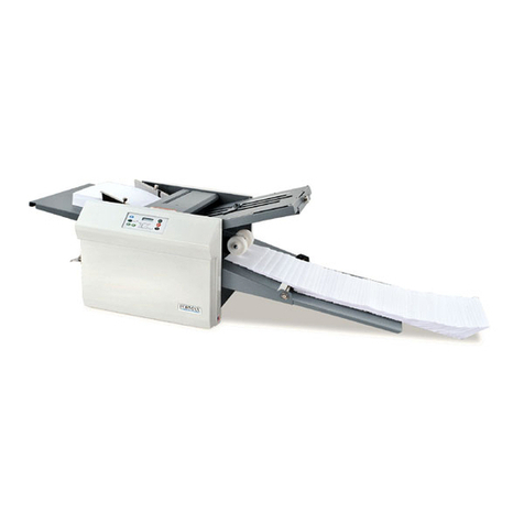
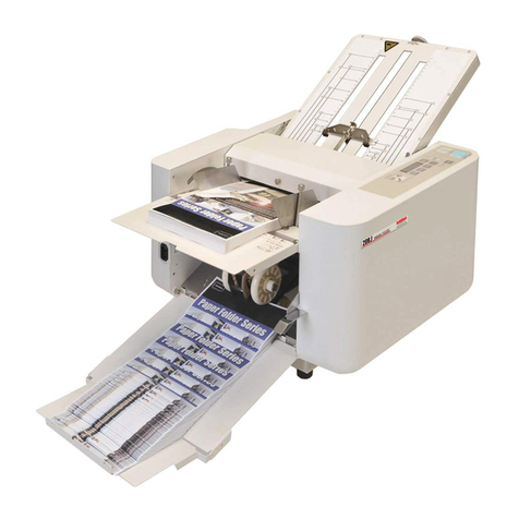
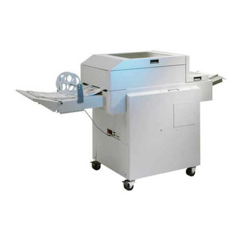
Electrolux IC44819FFS User manual

051020xx/GB
20.17
Installation manual
Feeder Ironer Folder
& Stacker
IC44819FFS – IC44825FFS – IC44832FFS
Translated from french

.

00
0209
Notice Date Page
05102004
INSTALLATION
MANUAL 0. Table of contents
General instructions
Environmental information ........................................................................................... 1/1
Preliminary instructions ................................................................................................ 1/2
Locking and tagging procedure .................................................................................... 1/3
Handling/Weight
Handling ....................................................................................................................... 1/4
Packing - Weight .......................................................................................................... 1/5
Technical characteristics
Technical characteristics .............................................................................................. 1/6
Sound level .................................................................................................................. 7/6
Label of energetic performances .................................................................................. 7/6
Installation/Putting into service
Working place lighting .................................................................................................. 1/7
Supplies ....................................................................................................................... 1/7
Unpacking .................................................................................................................... 1/7
Remove of the transport locks tted ............................................................................. 2/7
Installation .................................................................................................................... 4/7
Mechanical installation ................................................................................................. 5/7
Electrical connection .................................................................................................... 7/7
Steam connection ........................................................................................................ 13/7
Gas connection ............................................................................................................ 15/7
Connection of the evacuation system .......................................................................... 23/7
Connection of the stacker ............................................................................................ 28/7
Compressed air connection ......................................................................................... 29/7
Operating inspection
Direction of the rotation checking ................................................................................. 1/8
Appendices
Washing symbols ......................................................................................................... 1/9
Conversion measurement units ................................................................................... 1/9
Pages/Chapters
The manufacturer reserves the right to modify construction and equipment characteristics.

0708 1 0
Notice Date Page
05102004 INSTALLATION
MANUAL
This page is left blank on purpose.
0. Table of contents

0308 1 1
Notice Date Page
05102004
INSTALLATION
MANUAL
Environmental information
Concerned by providing the end user with useful and necessary environmental information, we
wish to precise :
Data about energetic consumptions, wastes (atmospheric and liquid) and sound level are
indicated in the paragraph "Technical characteristics".
Forseeing its recycling, this machine is fully dismantle.
This machine is free from any asbestos.
Our machine packing complies with the provisions of rule 98-639 dated July 20th 1998
regarding environmental demands.
For additional information, do not hesitate to consult our environmental department.
Scrapping of machine
When the machine is no longer to be used, it must be submitted to a recycling facility for destruction. The
majority of the components in the machine can be reused, but it also contains other material that must be
taken care of in the correct way. Therefore, never mix the machine or its parts with domestic waste as this
may lead to health hazards or damage to the environment.
1. Environmental
information

0608 2 1
Notice Date Page
05102004 INSTALLATION
MANUAL
This page is left blank on purpose.
1. Environmental
information

0308 1 2
Notice Date Page
05102004
INSTALLATION
MANUAL
A ash of lightning with an arrow at
its end displayed inside an equilateral
triangle, warns the user about the
presence of uninsulated "dangerous
current" sufcient in intensity to cause
electrocution.
An exclamation mark inside an
equilateral triangle offers the user
important advice about usage, servicing
and hazardous conditions.
This symbol warns the user that there
are mechanisms inside the machine
which can be dangerous. The protective
housing must be in place during use.
This symbol warns the user of the
presence of high temperatures which
could cause severe burns. Some
surfaces can reach close to 200 °C
(392 °F).
Explanation of graphic symbols
Preliminary instructions
Before any use, it is compulsory to read the instruction handbook.
Users must have learnt how the machine operates.
In order to prevent any risk of re or explosion, ammable products should never be used to
clean the machine.
Any repair or maintenance intervention should be carried out by qualied personnel only.
2. Preliminary instruction

0308 2 2
Notice Date Page
05102004 INSTALLATION
MANUAL
2. Preliminary instructions
SAFETY
The mechanical and electrical installation
of the machine should only be done by
qualied personnel.
CAUTION
Do not use the machine unless it is
plugged into a correctly earthed power
socket complying with standards in
force.
CAUTION
For your personal safety, never use
the machine without the protective
housings.
CAUTION
Disconnect the machine electrical
power supply before doing any repair or
servicing work.
CAUTION
This machine should be installed
in conformance to the health and
safety regulations, and only used in a
sufciently aerated area.
Check the instructions before installing
or using the machine.
Disconnect all sources of energy and let the ironing cylinder cool down before any
intervention on the machine.
The high temperature of the ironing cylinder may cause serious burns ; avoid touching the hot
surfaces.
Never iron if the nger protection does not function.
The machines comply with the European Directive EMC (Electromagnetic Compatibility). They
have been tested in laboratory and approved as such. It is so prohibited to add wires or non
shielded electric cables in the cabinets, strands or cables' troughs.

0814 3 2
Notice Date Page
05102004
INSTALLATION
MANUAL
It is specially advised not to install the machine on a synthetic oor
covering. The frictional electricity may hinder the good working of
the machine.
Under no circumstances should a gas-heating machine be installed
in a building which includes a dry-cleaning machine.
This is particularly important for your safety and that of others.
The consequence is an immediate cancellation of the warranty.
The machine can work without the protective casing when the
electric supply is not cut off.
Interlock the main isolating switch with a padlock.
Close the steam inlet valves.
If you detect gas smells, turn off the gas, open the windows, do not
activate any switch and warn the maintenance service.
The warranty might be cancelled if these instructions are not
complied with.
2. Preliminary instructions
CAUTION
For your own safety, it is prohibited and dangerous to solder the
ironing cylinder. If a leak occurs, never try to repair it yourself.
Ask our technical departments for advice.
IMPORTANT
When using the machine in automatic folding mode, you could
catch your ngers when the sheet removal actuator ascends/
descends with the anti-static device and in folding arm
movements.
Do not operate on the machine without powering down
beforehand.

0608 4 2
Notice Date Page
05102004 INSTALLATION
MANUAL
2. Preliminary instructions
This page is left blank on purpose.

1108 1 3
1
2
3
4
Notice Date Page
05102004
INSTALLATION
MANUAL
Locking and tagging procedure
Put the main switch
to Off and lock
the handle with
a padlock in one
of the three holes
provided for this
purpose.
Always respect
items 2, 3 and 4
carefully before
doing any repair or
maintenance work on
the machine.
Close the stop valves
for the other supplies
(gas, steam, compressed
air) to stop and lock
their handle with a
padlock.
Open the xed
protectors (casings,
doors) with the key
provided or a special
tool.
Close and carefully
lock the xed
protectors.
Unlock the stop
valves and the main
switch.
Do the maintenance.
A red insert at the beginning of this instruction handbook schematically shows the locking and
tagging procedure described below. If you wish, you can detach this insert and display it close to the
machine to remind maintenance personnel of the safety instructions.
3. Locking and
tagging procedure

0308 2 3
Notice Date Page
05102004 INSTALLATION
MANUAL
3. Locking and
tagging procedure
This page is left blank on purpose.

1504 1 4
D2411
Notice Date Page
05102004
INSTALLATION
MANUAL 4. Handling
Handling
SAFETY
It is obligatory that all these operations are undertaken by handling
specialists.
1/ Lifting with handling straps
Lifting in that case can only be done with handling straps (C - minimum capacity 2500 daN / L -
minimum length 4m) which bear weight of the machine.
2/ Lifting with a fork-lift truck
This can be carried out from the front or back, and at the centre of the machine using forks with
minimum length of 1,50 m (59") only with the pallet.
If necessary, set the adjustment feet of the machine in such as way as to allow the forks of the
stacker truck to make contact correctly.
CAUTION
You should never handle the machine in
its longitudinal side with a fork-lift truck.
Important risk of parts deterioration for
those xed under the machine.

1504 2 4
D1583
>4 m
Notice Date Page
05102004 INSTALLATION
MANUAL
4. Handling

1504 3 4
74032516
500 daN
D2226
Notice Date Page
05102004
INSTALLATION
MANUAL 4. Handling
CAUTION
In order to avoid any
bending of casings, you
should never climb and
stand on top of the machine.
Handling the stacker
• The stacker can be lifted using handling
straps (minimum capacity: 500 daN) able to
support the weight of the stacker.
• The stacker can also be wheeled over a
smooth at surface using its 4 wheels
3/ Moving along the ground
The machine frame is made up of two parallel spars, making ground moving possible by means
of rollers, grinding tracks or a trolley.
The two handling angles (B) can be used to lift the machine using hydraulic jacks or poles, so
that rollers can be slipped under the girder.

0608 4 4
Notice Date Page
05102004 INSTALLATION
MANUAL
4. Handling
This page is left blank on purpose.

1209 1 5
D0476
2650 1270 1800
3280 1270 1800
3910 1270 1800
2705 1325 1890
3335 1325 1890
3965 1325 1890
1370 1370 1570
1630 1630 1735
1815 1815 1930
Notice Date Page
05102004
INSTALLATION
MANUAL 5. Packing - Weight
Packing
Pallet dimensions in mm Size A Size B Size C
Dryer-ironer Type 4819
Dryer-ironer Type 4825
Dryer-ironer Type 4832
Crate dimensions in mm Size A Size B Size C
Dryer-ironer Type 4819
Dryer-ironer Type 4825
Dryer-ironer Type 4832
Weight
Weight in kg (machine + palett) Gas Electric Steam
Dryer-ironer Type 4819
Dryer-ironer Type 4825
Dryer-ironer Type 4832
Stacker
Weight in kg : 175 (stacker) - 345 (stacker + pallet)

0309 1 6
D1690
980B
C
C
125
75 50
70
140
140
Ø 60
190
40
35
40 40
A
500
K
K
G
G
F
L
L
J
J I H
H-I
1090 90
1820 500
950
1030
1010
950
1590
415
225
535
550
630
300
675
110
Notice Date Page
05102004 INSTALLATION
MANUAL
6.Technical
characteristics
Top view
Right view
Front view

0314 2 6
Amm 3555 4185 4815
Bmm 2575 3205 3835
Cmm 2295 2925 3555
mm 479 479 479
mm 457 457 457
mm 1910 2540 3170
m/min 1.5-11 1.5-11 1.5-11
m² 2.20 2.90 3.60
m² 2.10 2.70 3.40
kg/h 35 46 59
kg/h 38 48 59
kg/h 57 75 93
kg 1300 1545 1715
kg 1405 1545 1715
kg 1500 1650 1830
kg 175 175 175
m² 3.03 3.78 4.52
m² 1.78 1.78 1.78
F
G
Hmm 20 (3/4") 20 (3/4") 30 (3/4")
kPa 1000 1000 1000
Imm 10 (3/8") 10 (3/8") 10 (3/8")
Jmm 20 (3/4") 20 (3/4") 20 (3/4"
KØ mm 160 160 160
800/740 950/880 1010/960
Pa 880 880 880
Pa 200 200 200
LØ mm 6/8 6/8 6/8
bar 5.5-7 5.5-7 5.5-7
l/h 280 280 280
kW 2.9 2.9 3.2
kW 39 52 65
kWh 2.7 2.7 3
kW 35.75 46.10 56.75
kW 32.85 43.20 53.55
kWh 34.30 44.25 54.48
kW 2.9 2.9 3.2
kWh 2.7 2.7 3
kg/h 83 110 141
dm³ 300 398 497
Notice Date Page
05102004
INSTALLATION
MANUAL
6.Technical
characteristics
Characteristics IC44819FFS IC44825FFS IC44832FFS
AOverall width
BIroner width
CWidth between feet
Ø cylinder
Gas / Electric heating
Steam heating
Effective working width
Ironing speed, mini-maxi
Heating surface
Gas / Electric heating
Steam heating
Capacity max. water evaporation, with 50 % residual moisture and 100 % cylinder utilization
(according to ISO 9398-1)
Gas heating / Dubixium
Electric heating / Dubixium
Steam heating
Ironer net weight
Gas heating / Dubixium
Electric heating / Dubixium
Steam heating
Stacker net weight
Ironer oor area
Stacker oor area
Connections
FMain switch to connect electric main cable
GInlet for electric main cable
HSteam inlet
Maximum supply pressure
ICondensate return
JGas inlet
KDrain of vapour or burnt gas
Exhaust air max. with no pressure at 15 °C
Gas/Elec. & Steam m³/h
Total pressure with no ow
Admissible pressure drop on evacuation
LAir inlet
Air pressure, mini-maxi
Consumption
Consumptions
Gas heating / Dubixium
Installed electric power
Installed heating power
Maximum electrical consumption
Electric heating / Dubixium
Installed electric power
Installed heating power
Maximum electrical consumption
Steam heating
Installed electric power
Maximum electrical consumption
Max. steam consumption at 900 kPa
Inner volume steam cylinder
Heat loss : 3 % of installed heating power

1108 3 6
D0267
C
D
A
B
1m
(40”)
(40”)
1m
1m
(40”)
IC44819 FFS IC44825 FFS IC44832 FFS
A73 73 73
B72 72 72
C72 72 72
D72 72 72
Notice Date Page
05102004 INSTALLATION
MANUAL
6.Technical
characteristics
Sound level
Airborne noise emitted by the machine
(values established from measurements
made on machine at points A, B, C, and D).
Weighted sound pressure level (A) in dB (A)
Label of energetic performances (gas heating only)
The global output hg of the gas heated ironer is determinated according to a standardised
method and shall not be lower than 50%.
This output minimal level is indicated on the machine’s marking by the symbol .
Beyond the output minimal level hereabove specied, a label of energetic performance is given
to the machine according to its global output hg and according to the hereunder chart.
Symbolisation of the label Value of the output hg
50% <= hg < 65%
65% <= hg < 80%
hg > 80%
The indication of the energetic performance of the ironer is of .
This manual suits for next models
2
Table of contents
Other Electrolux Folding Machine manuals