Electrolux WE170V User manual

Service manual
Washer extractor
WE170V, WE170P
438 9167-20/EN
2015.03.03
Original instructions


3
INDEX
1General information.................................................................................................................................. 6
2WARNINGS.............................................................................................................................................. 7
3Control panel ............................................................................................................................................ 8
3.1General characteristics...................................................................................................................... 8
3.2General Characteristics and Control Panel........................................................................................ 9
3.3Programme selector knob.................................................................................................................. 9
3.4Pushbuttons....................................................................................................................................... 9
3.4.1On/off button................................................................................................................................. 9
3.4.2Spin time button............................................................................................................................ 9
3.4.3Option buttons .............................................................................................................................. 9
3.4.4Delay start button........................................................................................................................ 10
3.4.5Start/pause button ...................................................................................................................... 10
3.5Display............................................................................................................................................. 11
3.5.1Spin time digits........................................................................................................................... 11
3.5.2Phases symbols.......................................................................................................................... 11
3.5.3Child Lock................................................................................................................................... 12
3.5.4Delay .......................................................................................................................................... 12
3.5.5Time Digits.................................................................................................................................. 12
3.5.6Extra Rinse symbol..................................................................................................................... 12
3.5.7No softner symbol....................................................................................................................... 12
4Functionalities......................................................................................................................................... 13
4.1On/Off Button................................................................................................................................... 13
4.2Stand-Off mode behavior................................................................................................................. 13
4.3Cycle start / pause / change............................................................................................................ 13
4.4Hi-fi Selector.................................................................................................................................... 14
4.5Buttons Combinations...................................................................................................................... 14
4.5.1Child Lock mode......................................................................................................................... 14
4.5.2Demo mode................................................................................................................................ 15
4.5.3Diagnostic mode......................................................................................................................... 15
4.6Buzzer............................................................................................................................................. 15
4.7Display behaviors ............................................................................................................................ 15
4.7.1Child lock symbol........................................................................................................................ 15
4.7.2Cycle Phases symbols................................................................................................................ 15
4.8Faults/warnings signals ................................................................................................................... 16
4.8.1Selection error ............................................................................................................................ 16
4.8.2Warnings .................................................................................................................................... 16
5DEMO MODE......................................................................................................................................... 17
5.1Access to DEMO settings................................................................................................................ 17
5.2Exiting DEMO mode........................................................................................................................ 17
6DIAGNOSTICS SYSTEM ....................................................................................................................... 18
6.1Accessing diagnostics ..................................................................................................................... 18
6.2Quitting the diagnostics system....................................................................................................... 18
6.3Diagnostic test phases..................................................................................................................... 19
7ALARMS................................................................................................................................................. 21
7.1Displaying the alarms to the user..................................................................................................... 21
7.2Reading the alarms.......................................................................................................................... 22
Rapid reading of alarms................................................................................................................................. 23
7.3Deleting the last alarm..................................................................................................................... 23
8OPERATING TIME COUNTER............................................................................................................... 24
8.1Reading the operating time.............................................................................................................. 24
8.2Display of total operating time.......................................................................................................... 24
9Options................................................................................................................................................... 25
9.1Description of options...................................................................................................................... 25
10TECHNICAL CHARACTERISTICS......................................................................................................... 27
10.1Detergent container......................................................................................................................... 28
10.1.1Operating principle...................................................................................................................... 28
10.1.2Arranging the flap in the detergent container.............................................................................. 29
10.2Detergent container and hoses - WE170V....................................................................................... 30
10.3Detergent container and hoses - WE170P....................................................................................... 31
10.4Drain pump...................................................................................................................................... 32
10.5Filter dial.......................................................................................................................................... 32
10.6Washing unit.................................................................................................................................... 33

4
10.7Electronic control............................................................................................................................. 34
10.8Anti-disturbance filter....................................................................................................................... 35
10.8.1General characteristics............................................................................................................... 35
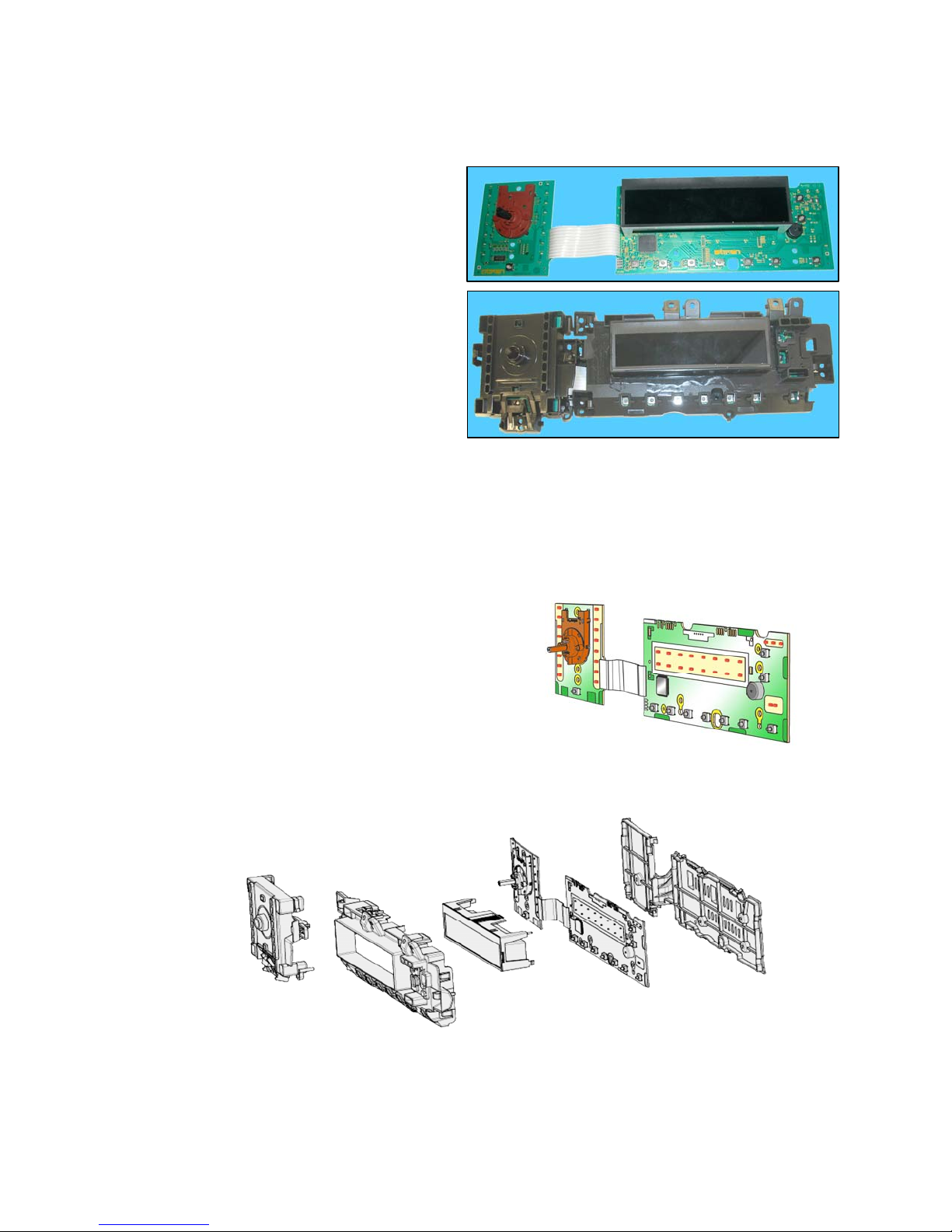
10.9Display board................................................................................................................................... 35
10.10Drain valve....................................................................................................................................... 36
10.10.1Working phases.......................................................................................................................... 38
10.10.2Replacement of drain valve ........................................................................................................ 39
10.11Heating element .............................................................................................................................. 40
10.11.1General characteristics............................................................................................................... 40
10.12Temperature sensor ........................................................................................................................ 41
10.12.1General characteristics............................................................................................................... 41
10.13Water level sensor........................................................................................................................... 42
10.13.1General characteristics............................................................................................................... 42
10.14Door lock safety interlock................................................................................................................. 43
10.14.1General characteristics............................................................................................................... 43
10.14.2Operating principle...................................................................................................................... 43
10.15Three-phase asynchronous motor - Inverter.................................................................................... 45
10.15.1General characteristics............................................................................................................... 45
10.15.2Power supply to motor................................................................................................................ 45
10.16Inverter (Motor Control Unit)............................................................................................................ 46
10.16.1General characteristics............................................................................................................... 46
10.17Solenoid valves ............................................................................................................................... 47
10.17.1General characteristics............................................................................................................... 47
10.17.1.1Operating principle..........................................................................................................47
10.17.1.2Mechanical jamming of the solenoid valve......................................................................47
10.17.1.3Low water pressure.........................................................................................................47
10.17.1.4Diagram ..........................................................................................................................48
10.18Flowmeter........................................................................................................................................ 49
10.18.1General characteristics............................................................................................................... 49
10.18.2Operating principle of the flowmeter ........................................................................................... 50
10.19Drum light........................................................................................................................................ 51
11ALARM SUMMARY TABLE (Note that some alarms might not be valid for your appliance)................... 52
11.1Alarm codes for appliance with coin meter or external liquid supply system.................................... 56
11.2Detailed description of alarm codes................................................................................................. 56
11.2.1E9A - External liquid supply system configured but communication failure (before payment)..... 56
11.2.2EF9 — External liquid supply system configured but communication failure (after payment)...... 56
12ACCESSIBILITY.................................................................................................................................... 57
12.1Worktop........................................................................................................................................... 57
12.2From the worktop, you can access.................................................................................................. 57
12.2.1Main board.................................................................................................................................. 57
12.2.2Solenoid valve ............................................................................................................................ 59
12.2.3Control panel .............................................................................................................................. 59
12.2.4Display board/light diffuser/button springs/buttons assembly...................................................... 61
12.2.5Water level sensor...................................................................................................................... 63
12.2.6Detergent container.................................................................................................................... 63
12.2.7Detergent fill pipe........................................................................................................................ 64
12.2.8Upper counterweight................................................................................................................... 64
12.3Accessing the front part................................................................................................................... 64
12.3.1Door hinge - Door....................................................................................................................... 64
12.3.2Door safety interlock................................................................................................................... 65
12.3.3Drum light................................................................................................................................... 66
12.3.4Bellow seal ................................................................................................................................. 66
12.3.5Blade .......................................................................................................................................... 67
12.3.6Front panel ................................................................................................................................. 69
12.4From the front panel, you can access.............................................................................................. 70
12.4.1Front counterweight.................................................................................................................... 70
12.4.2Shock absorber........................................................................................................................... 70
12.4.3Drain water circuit....................................................................................................................... 71
12.4.4Pressure chamber ...................................................................................................................... 71
12.4.5Tub suspension springs.............................................................................................................. 73
12.4.6Shock absorber pin..................................................................................................................... 74
12.5Accessing the rear part.................................................................................................................... 75
12.5.1Back panel.................................................................................................................................. 75
12.6From the back panel, you can access.............................................................................................. 75

5
12.6.1Belt............................................................................................................................................. 75
12.6.2Plastic pulley............................................................................................................................... 76
12.6.3Inverter ....................................................................................................................................... 76
12.6.4Motor .......................................................................................................................................... 77
12.6.5Heating element.......................................................................................................................... 77
12.6.6Rear shock absorber .................................................................................................................. 77
12.6.7Welded tub assembly ................................................................................................................. 78
12.6.8Drain pipe/cabling support.......................................................................................................... 78
12.6.9Main drain pipe........................................................................................................................... 78
13External liquid supply connection............................................................................................................ 79
13.1Replacement of the external liquid supply I/O board........................................................................ 79
13.2Setting of the dip switches............................................................................................................... 79
13.3Uninstall the external liquid supply................................................................................................... 80
13.4Pump signal schedule...................................................................................................................... 80

6
1 General information
Low consumption mode
In order to reduce electricity waste when the cycle is not running, the appliances on this platform are
designed to enter consumption reduction mode:
“Stand-Off” mode
When the appliance is switched off at the ON/OFF button, it is in the “Stand-Off” or “virtual” off status. The
LEDs and the LCD screen are turned off and the buttons are disabled, although the main circuit board and
certain electrical components are electrically powered.
“Auto-off” mode
If, after 5 minutes, during the programme selecting phase or after the end of the cycle, the appliance
receives no further instructions, it is automatically turned off (for energy savings in conformity with the
standards on energy consumption).
All the settings are stored so that when the appliance is turned back on, the programme is ready or if the
auto-off mode was triggered after the end of the cycle, the user can see that the cycle ended normally, and
can restart it if necessary.
You have to unplug the appliance to cut off the power supply
“Zero Watt” mode
Some appliances are fitted with a circuit (in the main circuit board) called Zero Watt (0 Watt with an actual
consumption ~50 mW) which cuts off the power supply to the appliance:
a.) When you press the ON/OFF button to turn off the appliance, the Zero Watt circuit is triggered and cuts
off the supply voltage after a few seconds, just long enough to secure the washing machine (motor off,
door locked, etc…), the cycle and any options selected are reset, so that the next time the appliance is
turned on, it is ready to perform the programme.
(To open the door, you will have to wait one or two minutes for the door safety lock to be released).
b. If, after 5 minutes, during the programme selecting phase or after the end of the cycle, the appliance
receives no further instructions, it is automatically turned off, the Zero Watt circuit which cuts off the
supply voltage is triggered (for energy savings in conformity with the standards on energy consumption).
All the settings are stored so that when the appliance is turned back on, the programme is ready or if the
auto-off mode was triggered after the end of the cycle, the user can see that the cycle ended normally,
and can restart it if necessary.
If an alarm occurs during a washing programme, the auto off function is disabled, and an alarm is displayed.

7
2 WARNINGS
Any work on electrical appliances must only be carried out by qualified
technicians.
Before you access internal components, take the plug out of the socket to cut the
power supply.
Make resistance measurements, rather than direct voltage and current
measurements
When replacing the heating element, replace it with one
that has the same characteristics (2 thermal fuses) in order
not to compromise the safety of the appliance. Do not
remove/switch the NTC sensors between heating elements.
Always empty the appliance of all the water before laying it
on its side (see the relevant paragraph).
Never place the appliance on its right side (electronic control system side): some
of the water in the detergent dispenser could leak onto the electrical/electronic
components and cause these to burn.
When replacing components, please refer to the code shown in the list of spare
parts relating to the appliance.

8
3 Control panel
3.1 General characteristics
The control/display circuit board, inserted in
a plastic box, secured to the control panel
(the figure illustrates: the display board with
the side socket in which the selector is
fixed, connected together by a flat cable,
and the display board assembly).
The main circuit board is positioned at the rear of the appliance, receives commands from the display
board, powers the electrical components as well as communicating with the motor control board
(Inverter).
Positioning of LEDs and buttons
Display board assembly, exploded view
1. Selector board protection
2. Display board protection
3. LCD display
4. Display board and selector board
5. Rear protection
1 2 3
4 5

9
3.2 General Characteristics and Control Panel
Application pictures1:
The main characteristics are:
Hi-fi selector with 16 LEDs (positions) associated;
On/Off mechanical tact-switch button always on board;
7 function buttons:
oPre rinse button;
oPre wash button;
o2 option buttons;
oSpin time button;
oDelay start button;
oStart/pause button with 1 associated LED;
Small LCD custom display, negative red;
All the LEDs are red.
3.3 Programme selector knob
Refer to “Functionalities” chapter for a detailed description of Hi-fi selector usage.
3.4 Pushbuttons
3.4.1 On/off button
Refer to “Functionalities” chapter for a detailed description of On/Off usage.
3.4.2 Spin time button
The spin time is initially set to default value for that program. Each time the related button is pressed, the
time value is decreased by following pre-defined steps: 6m, 4m, 2m, 45s, 30s , 15s, 10s, 5s; once reached
the minimum allowed time (5 seconds) it restarts from the maximum time (configurable also on selector).
3.4.3 Option buttons
The four option buttons without associated LED are used to select:
Pre Rinse
Pre Wash
Extra Rinse
No Softner
1Remark: the pictures are only demonstrative, not in the final graphical release.

10
When pressing the button the option is enabled or disabled. When the option is enabled the associated
ICON switches on and cycle duration is updated in display digits.
3.4.4 Delay start button
The delay buttons is associated with one dedicated icon on the LCD. When the delay is active the icon is
switched on, both during program setup and delay phase in progress.
Each time the button is pressed, the delay time increase in the following way:
Up to 90 minutes in steps of 30 minutes
From 2 to 70 hours in steps of 1 hours
After “70h”, pressing again the button, the function is deactivated. Once the delay has been set and after 3
seconds of no key presses the digits will display again the program duration. To see the delay time again,
press once the button. After the machine is started the display will show the delay time counting down.
After cycle start, selected delay time can only be cancelled (machine must be put in pause first).
3.4.5 Start/pause button
The Start/Pause is used to start the cycle once the program and options have been set. Pressing the button
during the cycle will pause the machine to allow changing options or possibly open the door porthole (if
necessary conditions of temperature and water level are met). Press again to restart cycle.
The associated LED blinks slowly during programme setup, during the pause; it is lighted on steadily when
the cycle is in execution; it is lighted off when the cycle is ended with the door unlocked.

11
Key Key Combinations
The following key combinations are available in this user interface:
(*) Remark: Extra Rinse combination can be configured just to allow memorizing the option so that it is set
by default when selecting a washing program.
For the usage and the behaviour of these functions refer to “Functionalities” chapter.
3.5 Display
Initial revision:
The only available colour combination for display is red on black.
In the next paragraphs a description of the different icons.
Further info about display behaviour is described also in “Functionalities” chapter.
3.5.1 Spin time digits
The selected spin time is showed on display digits in "minutes & seconds" format:
"m.ss" for spin time >= 1 minute
"ss" without leading zeros for spin time <= 59 seconds
3.5.2 Phases symbols
Please refer to their description under “Functionalities” chapter.
Here below you can find the description of each phase:
Pre-rinse Pre-wash
Wash phase Rinse Phase Spin Phase
Function Button 1 Button 2
Child lock 1 2
Default Extra Rinse (*) 5 6
Buzzer enable/disable 3 4
Demo mode 6 7
Diagnostic mode 6 7

12
3.5.3 Child Lock
This segment of the lock is switched on when child lock is activated. It blinks if, with child lock activated, a
button is pressed or the rotary is turned.
Only with coin meter connected, after 5 minutes we have to disable door opening and cycle reset until the
end of cycle. The 5 minutes are counted after START command in execution or delayed state but not in
pause.
Child Lock is a function that allows the user to leave the appliance unsupervised with the door closed,
without having to worry that children might be injured by, or other persons cause damage to the appliance.
The basic points are:
all push buttons are disabled;
program cancelling after start not allowed when switching machine off and on;
door is kept closed as long as child lock is active, but not during programme setup and cycle end
phases;
a clear indication of Child Lock, such as a dedicated Icon has to be provided.
3.5.4 Delay
This icon is switched on during setup of the delay start or during delay phase after cycle start.
3.5.5 Time Digits
3 digits used to show cycle duration, errors, warnings, delay time. Please refer to their
description under “Functionalities” chapter.
3.5.6 Extra Rinse symbol
Extra Rinse has only 1 selection level. Pressing the button the option is enabled or disabled. When
the option is enabled the associated ICON switches on and cycle duration is updated in display
digits.
3.5.7 No softner symbol
If no Softener is selected, both internal drawer and external detergent system has to not use
related detergent.

13
4 Functionalities
4.1 On/Off Button
The aesthetics levels of the WE170P/V have a dedicated On/Off button always present. This button could
put the machine in a special low power consumption mode.
To switch on the appliance, simply press shortly the button. The user interface plays the dedicated jingle (if
buzzer is enabled) and switches the lights and display on according to default programme.
To switch off the appliance, press and hold the button for about 1 second. After this time, the user interface
plays the dedicated jingle (if buzzer is enabled) and all lights and display are switched off. All selected
options and the possible programme in progress are reset.
4.2 Stand-Off mode behavior
When the machine is switched off via On/Off button, the appliance goes in Stand-Off mode where it is
“virtually switched off”: all LEDs and display are lighted off and buttons are disabled, but the electronic
boards are supplied anyway.
4.3 Cycle start / pause / change
When a programme is selected and the door porthole is closed, to start the cycle simply press the
Start/Pause button: related LED stops flashing and becomes steady while the display (if present) updates
accordingly. Pressing Start/Pause button during the cycle the machine is paused: if door unlocks it means
there are the conditions to open it and add laundry, usually during the first minutes after water load. In pause
it is allowed changing options, but not programmes: in this case a reset via On/Off button is needed.
In all cases the display updates switching from cycle end indication to pause or execution state: time digits
show updated time to end.
Cycle running
Once the user has pressed start to begin the washing process, the feedback about the progress of the
washing program is given on display or lights. The cycle duration decreases in the time digits of display.
The user interface show which is the washing phase in progress by making blinking the related icon on
display, while other phase icons remain lighted on steadily. The number and sequence of phase icons is
according to user interface level and display.
So, for example, during prewash blinks the prewash phase symbol, during wash blinks the wash phase
symbol, during rinses blinks the rinse phase symbol, during drain and final spin blinks the spin phase
symbol, at cycle end all phases symbols remain steady and time digits show “0”.
Cycle end
When the cycle is finished and the door is unlocked, the cycle end status is showed. Within 5 minutes,
before entering Stand-off mode the user is allowed to recall and start again the just finished program,
changing any option if desired, or select a new program without necessarily switching off and on the
machine.
The possible actions to exit the cycle end phase are:
-pressing any button (On/Off excluded) the user interface goes in setup phase keeping and showing
the previously selected program and options; pressing then the Start/Pause button the previous
cycle is repeated;
-turning selector knob the user interface goes in setup phase and shows new program and options
info corresponding to the new selector position;
-pressing On/Off button the user interface switches off and machine goes in Stand-off mode.

14
4.4 Hi-fi Selector
The number of position is not configurable and it is always 16, since it is strictly linked to the programme
lights.
Compared to a traditional absolute selector, the Hi-fi one has no index on the knob and no reset position.
The knob itself doesn’t point to any position in the control panel; hence the selected programme is indicated
by the associated LED.
To reset a cycle in progress just press the On/Off button.
When the machine is switched on, the upper right position is selected by default (if no “special modes, e.g.
diagnostic, return from power fails, demo mode etc). When the rotary is turned clockwise or anti-clockwise in
setup, the corresponding LED of selected programme is lighted on and the LCD display info changes
accordingly.
4.5 Buttons Combinations
Some additional extra functions can be set using “buttons combinations”, that is keeping pressed together
for some seconds specific couples of buttons.
Push buttons combinations can be configured for following functions:
Function Meanin
g
Default
Extra Rinse
Used to set and store Extra Rinse option. This function keeps its last selected status (set
or deselect) also after machine switching off. Settable only during the programme setup
for those cycles where the option is available; the feedback is given on dedicated Extra
Rinse LCD icon.
Buzzer on/off
Activates/deactivates the buzzer. This function keeps its last selected status (set or
deselect) also after machine switching off. Settable during the programme setup; the
feedback is given by 2 short beeps when deactivating sounds, by 1 click when re-
activating sounds.
Child Lock
Mode
Locks the user interface to prevent children changing program setup or starting the cycle.
This function keeps its last selected status (set or deselect) also after machine switching
off. Always settable; the feedback is given on Child Lock LED or icon inside the display.
Demo mode
Demonstration mode, to show to customers in the sales shop how the machine works by
simulating the washing cycle. Settable within 7 seconds from machine switching on; the
feedback is given by “dEM” text flashing on cycle time digits for 3 seconds. Demo mode
remains active also after machine switching off via On/Off button; pressing On button
again will flash “dEM” or LEDs as above described. Unplug machine to exit mode.
Diagnostic
Mode Factory/Service mode for machine testing. The mode is exited when switching machine
off. Settable within 7 seconds from machine switching on; the feedback is given by all
LEDs or LCD icons flashing in sequence.
Diagnostic and Demo modes can be set only within 7 seconds from machine switching on, provided that
selected programme position is the first for Diagnostic and the third for Demo.
Further info on some of such functions is provided following.
4.5.1 Child Lock mode
Child Lock is a function that allows the user to leave the appliance unsupervised with the door closed,
without having to worry that children might be injured by, or other persons cause damage to the appliance.
The basic points are:
all push buttons are disabled;
program cancelling after start not allowed when switching machine off and on;
door is kept closed as long as child lock is active, but not during programme setup and cycle end
phases;
a clear indication of Child Lock, such as a dedicated Icon has to be provided.
Push buttons
All push buttons are disabled as long as Child Lock is active. Only On/Off and buttons combination to unlock
machine and to enter in diagnostic mode are always enabled.
Cancelling the program
To cancel a running program after cycle start, Child Lock has to be deactivated first pressing the foreseen
buttons combination and then the machine has to be switched-off.

15
If the machine is switched-off and on during cycle execution without unlocking it, cycle automatically
continues like after a power failure situation.
Door status
After cycle start, the door is kept locked as far as the cycle end is reached. To open it if needed before cycle
end, Child Lock has to be deactivated first pressing the foreseen buttons combination and then pausing the
machine pressing Start/Pause button: if the machine is in safety conditions (low water level and low
temperature) the door device unlocks.
If the machine is switched-off during cycle execution for more than one minute (door lock device unlocks in
the meantime), when it is switched-on again the door is automatically locked, unless it has been manually
opened in the meantime: in this second case machine wakes up in pause and waits for user confirmation to
go on with cycle execution (pressing Start button after that Child Lock has been deactivated).
4.5.2 Demo mode
Demonstration mode is used to show to customers in the sales shop how to interact with user interface
panel and how the machine works by simulating the washing cycle.
The appliance works and can be operated in the same way as in normal user mode, allowing to select any
program with washing options in order to see cycle time and how options can affect it.
The difference in Demo Mode is that, once the cycle is started, only the motor moves: actions such as water
loading, water draining and heating are not performed since they cannot be managed in the shop.
4.5.3 Diagnostic mode
Diagnostic mode is used by factory or service people to test the machine and check for possible faults by
reading the alarms status history.
4.6 Buzzer
A multi-tone buzzer is provided to sound in following cases:
-switching machine on and off, with 2 different short jingles;
-pressing a button, with a very short “click” sound;
-when the cycle is finished, for about 2 minutes with a specific sequence of three long beeps (1sec
on - 1 sec off - 1sec on - 1 sec off - 1sec on) repeated every 15 seconds;
-when alarms/warnings occur, for about 5 minutes with a specific sequence of three short beeps
repeated 3 times every 15.
-during program selection, when knob moves, with a very short “click” sound as pushbuttons.
The buzzer can be active or not by configuration; anyway the default factory setting has to be active to
meet the norms regarding eyesight handicap people. To deactivate it the specific push buttons combination
has to be used (see “Buttons Combinations” paragraph).
When deactivated the buzzer doesn’t play the on/off jingles and cycle end melody, while sounds anyway in
case of button “click”, knob movements and alarm/warnings occurrence.
Volume level is pre-fixed and can’t be changed by user.
4.7 Display behaviors
4.7.1 Child lock symbol
This symbol shows the status locked/unlocked of the user interface. When child lock is set, related icon on
display is lighted-on. Pressing any button, the icon blinks for a while to remind that the user interface is
locked.
4.7.2 Cycle Phases symbols
Cycle phase icons are lighted-on steadily during the setup phase to show which phases are included in the
cycle. During cycle execution, the icon of the phase in progress blinks every half a second, remains steady
when the phase has passed; same behaviour if the machine is paused during the cycle.

16
4.8 Faults/warnings signals
4.8.1 Selection error
The selection errors are noticed to customer by a flashing “Err” text on cycle time digits; buzzer doesn’t
sound a specific melody and Start/Pause LED doesn’t flash.
The signalling is displayed for about 1 second in following cases:
-if coin meter is present and the user try to start a cycle without payment;
-when an incompatible option button with selected washing program has been pressed;
-when an option button is pressed or the selector is moved during the cycle execution.
4.8.2 Warnings
When a machine fault is detected, a warning is displayed on cycle time digits with “Exx” format.
The faults that are noticed to customer are:
-E10 : tap closed, due to water loading timeout
-E20 : clogged filter, due to water draining timeout
-E40 : door not properly closed, due to device locking timeout
-E90 : no communication between main boards and coin operated machine or detergent dispenser
-EF0 : detergent overdosing
-EH0: mains supply problems, due to voltage/frequency out of standard working range
Warning code/message is displayed as long as the fault condition is present. The buzzer sounds for about 5
minutes, but not in case of EH0.
For the first three codes, once the problem has been solved, pressing Start/Pause button the warning is not
shown anymore and buzzer stops sequence.

17
5 DEMO MODE
A special cycle is designed to demonstrate the operation of these appliances in shops, without connecting
them to the water mains. This way, any one of the programmes can be selected and, once the start
button/sensor has been pressed/touched (START/PAUSE), the appliance will only perform some of the
phases of the programme, skipping those which cannot be performed (water fill, drain, heating).
The cycle takes place as follows:
the door lock is enabled regularly (door locked during operation, possibility of opening it at the end of the
cycle or when paused),
Motor: all low speed movements are enabled, the pulses and spin are disabled,
the water fill solenoid valves and the drain pump are disabled,
display: as the cycle phases are very fast (one second in the demo cycle corresponds to approximately
one minute in the actual cycle) the end time decreases by 1 unit per second. Bear in mind that the end
time does not always correspond to the actual cycle time.
5.1 Access to DEMO settings
The operations listed below must be carried out within 7 seconds.
Do not start the machine with this combination of buttons pressed, only when accessing
diagnostic mode
1. Switch on the appliance using the ON/OFF button
2. Turn the selector dial until the third LED in the right-hand row is on.
3. Press the START/PAUSE button and the nearest option button simultaneously (as shown in the figure).
4. Hold the buttons down (approximately three or five seconds) until “dEM” flashes for a short time.
5.2 Exiting DEMO mode
To quit the demo mode, unplug the appliance at the socket, because the ON/OFF button does not function.

18
6 DIAGNOSTICS SYSTEM
6.1 Accessing diagnostics
The operations listed below must be carried out within 7 seconds.
Do not start the machine with this combination of buttons pressed, only when accessing
diagnostic mode
1. Switch on the appliance using the ON/OFF button. The first LED in the right hand row will light up.
2. Press the START/PAUSE button and the nearest option button simultaneously (as shown in the
figure).
3. Hold the buttons/sensors down/pressed until the LEDs and symbols begin to flash in sequence
(approximately 3 seconds).
In the first position, the operation of the buttons, of the related LEDs and of the groups of symbols shown
on the LCD screen is checked; turn the programme selector dial clockwise to run the diagnostic cycle for
the operation of the various components and to read any alarms (see diagnostic testing on the following
page).
During this phase, if any key combination is pressed (except for the one relating to diagnostics), all the
combinations of options stored are deleted (Extra rinse, No buzzer, etc..).
6.2 Quitting the diagnostics system
To exit the diagnostic cycle, switch the appliance off, then back on and then off again.

19
6.3 Diagnostic test phases
Irrespective of the type of PCB and the configuration of the programme selector, after entering the diagnostic
mode, turn the programme selector dial clockwise to perform the diagnostic cycle for the operation of the
various components and to read any alarms.
Concurrently, a selector control code is shown on the LCD display, which indicates for two seconds the
description in the last column of the table below.
(all alarms are enabled in the diagnostic cycle).
Selector
position Components activated Working conditions Function tested LCD display
1
-The LEDs, groups of symbols
in the LCD screen and the
backlight of the display are
turned on in sequence
-Press a button/sensor to turn
on the group of icons in the
LCD screen or the
corresponding LED and the
buzzer sounds at the same
time
Always active. User interface
functions.
2
-Door safety interlock
-Wash solenoid
Door closed.
Water level below
anti-flooding level.
Maximum time
5 mins.
Water fill to wash
compartment.
Water level in
the tub (mm)
3
-Door safety interlock
-Pre-wash solenoid
Door closed.
Water level below
anti-flooding level.
Maximum time
5 mins.
Water fill to pre-
wash
compartment
Water level in
the tub (mm)
4
-Door safety interlock
-Solenoid valve
pre-wash and wash
Door closed.
Water level below
anti-flooding level.
Maximum time
5 mins.
Water fill to
conditioner
compartment.
Water level in
the tub (mm)
5
-Door safety interlock
-Third solenoid valve
Door closed.
Water level below
anti-flooding level.
Maximum time
5 mins.
Water fill to third
solenoid valve
compartment. Water level in
the tub is
displayed (mm)
6
-Door safety interlock
-Fourth solenoid valve (hot
water where featured)
Door closed.
Water level below
anti-flooding level.
Maximum time
5 mins.
Water fill to
fourth solenoid
valve
compartment. Water level in
the tub is
displayed (mm)
7
-Door safety interlock
-Wash solenoid, if the water in
the tub is not enough to cover
the heating element
-Heating element
Door closed.
Water level above the
heating element.
Maximum time
10 mins up to 90 °C.
(*)
Heating.
Circulation.
Temperature in
°C measured
using the NTC
probe
8
-Door safety interlock
-Wash solenoid, if the water in
the tub is not enough to cover
the heating element
-Motor (55 rpm clockwise,
55 rpm anti-clockwise,
250 rpm pulse)
Door closed.
Water level above the
heating element.
Check for leaks
from the tub.
Drum speed in
rpm/10

20
9
-Door safety interlock
-Drain pump
-Motor up to 650 rpm then at
maximum spin speed (**)
Door closed.
Water level lower
than anti-boiling level
for spinning.
Drain, calibration
of analogue
pressure switch
and spin.
Drum speed in
rpm/10
11
-Reading/Deleting the last alarm ----- ----
12
÷
16
-The LEDs, groups of symbols
in the LCD screen and the
backlight of the display are
turned on in sequence
-Press a button/sensor to turn
on the group of icons in the
LCD screen or the
corresponding LED and the
buzzer sounds at the same
time
Always active. User interface
functions.
(*) In most cases, this time is sufficient to check the heating. However, the time can be increased by repeating the phase without draining
the water: pass for a moment to a different phase of the diagnostic cycle and then back to the heating control phase (if the temperature is
higher than 80 °C, heating does not take place).
(**) The check at the maximum speed occurs without control of the A.G.S. and no garments must be inside the appliance.
This manual suits for next models
1
Table of contents
Other Electrolux Scrubber manuals

Electrolux
Electrolux W.55.H User manual

Electrolux
Electrolux WHB5 500H User manual

Electrolux
Electrolux Flymo Hover Vac Operating manual

Electrolux
Electrolux EFC 9650 User manual

Electrolux
Electrolux WH6-6 User manual

Electrolux
Electrolux Washer User manual

Electrolux
Electrolux W465H User manual

Electrolux
Electrolux AW 445 User manual