Electrolux EI15TC65HS - Undercounter Trash Compactor Operating manual

Publication #5995530945 December 2008
Technical Service Manual
Trash Compactor

2Safe Servicing Practices
Safe Servicing Practices
To avoid personal injury and/or property damage, it is important that Safe Servicing Practices be
observed. The following are some limited examples of safe practices.
DO NOT attempt a product repair if you have any doubts as to your ability to complete it in a safe1.
and satisfactory manner.
Before servicing or moving an appliance, remove the power cord from the electrical outlet, trip the2.
circuit breaker to the OFF position, or remove the fuse.
Never interfere with the proper operation of any safety device.3.
USE ONLY REPLACEMENT PARTS CATALOGED FOR THIS APPLIANCE. SUBSTITUTIONS MAY4.
DEFEAT COMPLIANCE WITH SAFETY STANDARDS SET FOR HOME APPLIANCES.
GROUNDING: The standard color coding for safety ground wires is GREEN, or GREEN WITH5.
YELLOW STRIPES. Ground leads are not to be used as current-carrying conductors. It is
EXTREMELY important that the service technician re-establish all safety grounds prior to completion
of service. Failure to do so will create a hazard.
Prior to returning the product to service, ensure that:6.
All electrical connections are correct and secure•
All electrical leads are properly dressed and secured away from sharp edges, high-temperature•
components, and moving parts
All non-insulated electrical terminals, connectors, heaters, etc., are adequately spaced away from•
all metal parts and panels
All safety grounds (both internal and external) are correctly and securely connected•
All panels are properly and securely re-assembled•
NOTE
This service manual is intended for use by persons having electrical and mechanical training and a
level of knowledge of these subjects considered acceptable in the appliance repair trade. Electrolux®
Home Products cannot be responsible, or assume any liability, for injury or damage of any kind arising
from the use of this manual.
Grounding Instructions
FOR PERSONAL SAFETY, THIS APPLIANCE MUST BE PROPERLY GROUNDED.
This power cord on this appliance is equipped with a three-prong (grounding) plug which mates with a
standard three-prong (grounded) receptacle.
If there is a two-prong outlet located where you will install the compactor, it is your responsibility to have
it replaced with a properly grounded three-prong wall receptacle.
DO NOT, UNDER ANY CIRCUMSTANCES, CUT OR REMOVE THE THIRD (GROUND) PRONG FROM
THE POWER CORD.
A 120-volt, 60 Hz., A.C., 15 amp fused and grounded electrical supply is required (time-delay fuse
or circuit breaker is recommended). It is recommended that a SEPARATE CIRCUIT serving only this
appliance be provided.
DO NOT USE AN EXTENSION CORD WITH THIS APPLIANCE.

3
Table of contents
Safe Servicing Practices............................................................ 2
Grounding Instructions.............................................................. 2
Features....................................................................................... 4
Section A – Installation.............................................................. 5
Free-Standing............................................................................... 5
Built-In Installation ........................................................................ 5
Mounting Straps....................................................................... 5
Under-Counter Opening .......................................................... 5
Cord Clamp ............................................................................. 6
Leveling the Compactor................................................................ 6
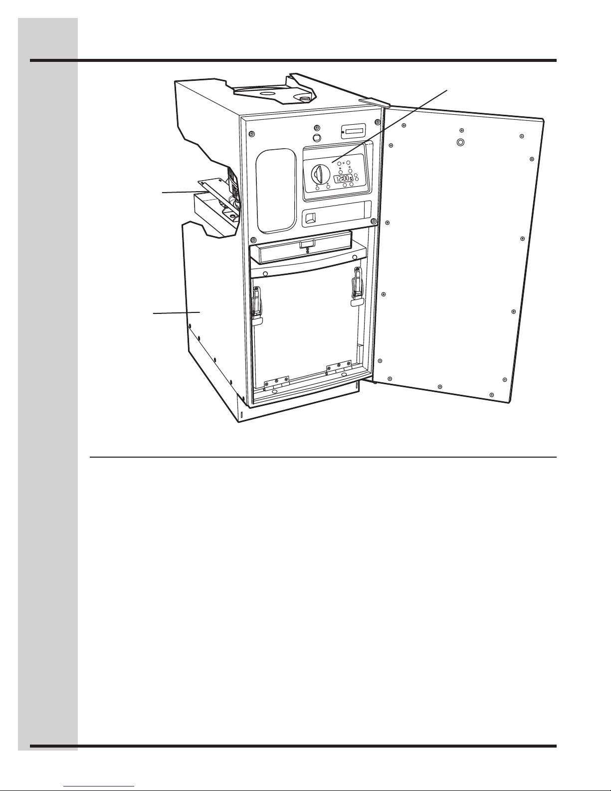
Section B – Cabinet.................................................................... 7
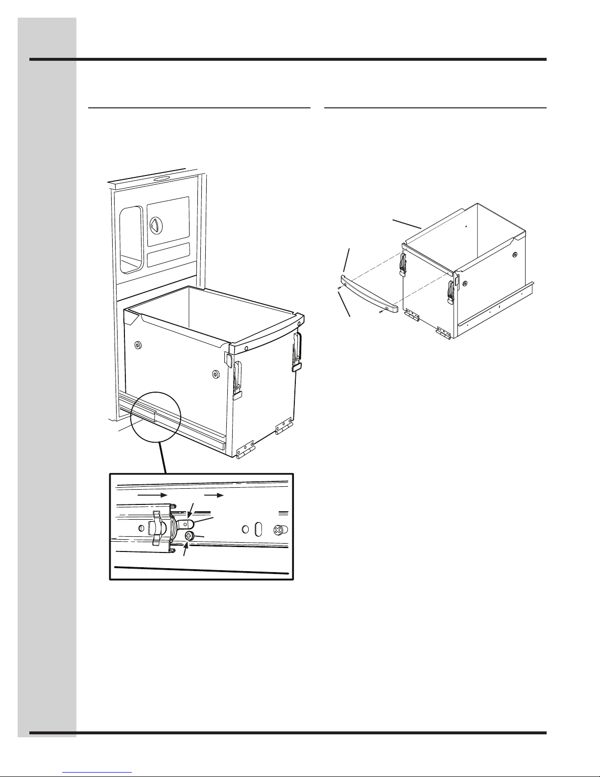
Trash Bucket ................................................................................. 8
Remove ................................................................................... 8
Bucket Handle .............................................................................. 8
Remove and Replace .............................................................. 8
Slide Rails (Cabinet)..................................................................... 9
Remove and Re-install ............................................................ 9
Slide Rails (Bucket) ...................................................................... 9
Remove and Re-install ............................................................ 9
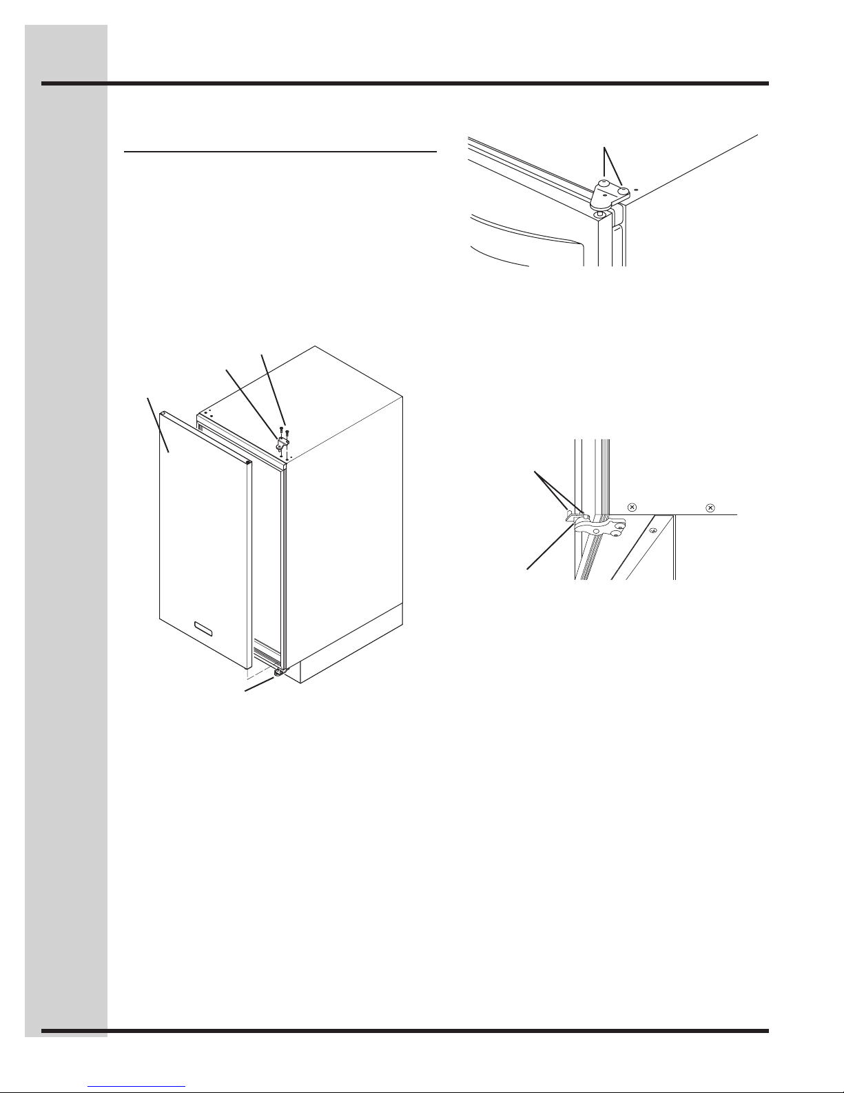
Door Assembly ............................................................................. 10
Remove and Re-install ............................................................ 10
Reverse Door Position ............................................................. 11
Door Handle ................................................................................. 12
Remove and Re-install ............................................................ 12
Safety Interlock Actuator............................................................... 12
Remove and Re-install ............................................................ 12
Gasket Assembly.......................................................................... 13
Remove and Re-install ............................................................ 13
Trim Cover Assembly.................................................................... 14
Remove and Re-install ............................................................ 14
Kick Plate...................................................................................... 14
Section C – Power Unit Mechanism.......................................... 15
Drive Belt...................................................................................... 16
Remove and Re-install ............................................................ 16
Main Motor.................................................................................... 17
Remove and Replace .............................................................. 17
Complete Power Unit Mechanism................................................. 18
Remove and Re-install ............................................................ 18
Drive Wheels ................................................................................ 18
Remove and Replace .............................................................. 18
Ram Screw Assembly................................................................... 19
Remove and Replace .............................................................. 19
Section D – Electrical Components.......................................... 22
Access to Components................................................................. 23
Remove Cabinet Cover............................................................ 23
Re-install Cabinet Cover.......................................................... 25
Control Panel Assembly ............................................................... 25
Remove and Re-install ............................................................ 25
Display Module Assembly............................................................. 26
Remove and Re-install ............................................................ 26
Power Supply Board..................................................................... 27
Remove and Re-install ............................................................ 27
Control Board ............................................................................... 28
Remove and Re-install ............................................................ 28
Key Switch.................................................................................... 28
Remove and Replace .............................................................. 28
Interlock Switch Assembly............................................................ 29
Remove and Re-install ............................................................ 29
Upper Limit Switch Assembly....................................................... 29
Remove and Replace .............................................................. 29
Lower Limit Switch........................................................................ 30
Remove and Replace .............................................................. 30
Motor Centrifugal Switch Assembly.............................................. 30
Remove and Replace .............................................................. 30
Motor Capacitor............................................................................ 31
Test, Remove and Replace...................................................... 31
Odor Disk Gear Motor (ICON Models Only)................................. 32
Remove and Replace .............................................................. 32
Power Cable ................................................................................. 33
Remove and Replace .............................................................. 33
Section E – Troubleshooting
Troubleshooting Table ................................................................... 34
Section F – Specifications
Specifications Table ...................................................................... 37
Section G – Diagrams and Parts Lists
Wiring Schematic for Model EI15TC65HS ................................... 38
Drawing and Parts List for Model EI15TC65HS ........................... 39
Wiring Schematic for Models E15TC75HPS & HSS .................... 40
Drawing and Parts List for Models E15TC75HPS & HSS ............ 41
Table of Contents

4
How the compactor works
The compactor compresses household trash up to 1/6 of its original volume. It will compact normal household trash
including milk cartons, glass and plastic bottles, containers and jars, tin cans, wrappings, boxes, food wastes, etc.
When you start the compactor, an electrically powered ram moves down into the trash bucket, compresses the trash
and then returns to the “UP” position and shuts off automatically.
NOTE: The ram travels about 2/3 of the way down into the trash bucket. Because of this, the trash bucket must be at
least 1/3 full before you will notice any compression.
Features
ELECTRICAL
COMPONENTS
(SECTION D)
POWER UNIT
MECHANISM
(SECTION C)
CABINET
(SECTION B)

5
Section A – Installation
Your compactor has been designed to require minimum
space without loss of capacity whether free-standing or
built-in.
Free-Standing
As shipped, the compactor is only configured for built-in
installations. This appliance can be converted from built-
in to free-standing with the use of Toe Kick Accessory Kit
Model ETC15TKH (sold separately).
If additional cord length is required for free-standing
installation, remove the cord clamp and wire tie on the
back of the unit.
CAUTION
Failure to use Toe Kick Assembly Kit Model
ETC15TKH in a free-standing installation may cause
the compactor to be unstable during operation.
Built-in Installation
MOUNTING STRAPS
TOP OF
COMPACTOR
FRONT OF
COMPACTOR
Two under-counter mounting straps are provided. Use
these straps to secure the compactor to the underside
of a countertop.
Fasten the slotted end of the straps to the compactor
using the holes in the top of the compactor cabinet as
shown.
NOTE: When installation compactor under granite or
solid surface countertops, bend the mounting straps so
they can be secured to the adjacent cabinetry.
UNDER-COUNTER OPENING
Opening
15" Wide
34-1/2" High
22" Deep
15" W
345/8" H
24" D
12" MIN
ELECTRICAL
OUTLET
The compactor requires an under-counter opening 15-in.
wide, 34-5/8-in. high, and 24-in. deep.
Plan to provide an electrical outlet in the opening that
meets all applicable electrical codes and requirements.
See “Grounding Instructions” on Page 2 for specific
information.

6Section A – Installation
CORD CLAMP
The compactor is equipped with a 6-ft. long power cord.
Use the cord clamp to prevent excess power cord from
being pinched beneath the cabinet during installation or
service.
CORD
CLAMP
Leveling the Compactor
Your compactor has four adjustable levelers; (2) rollers in
the rear and (2) legs in the front. They allow you to adjust
for uneven floors and also trim the unit up to fit an under-
counter installation.
BACK OF
COMPACTOR
WOOD
BLOCK
ADJUSTING
SCREWS
SLOTS
ROLLERS
To level the back of the compactor:
Tip the back of compactor up and onto a wood block.
Loosen the adjusting screws only far enough to move the
rollers to a higher or lower slot. Retighten the adjusting
screws and remove the wood block.
FRONT OF
COMPACTOR
WOOD
BLOCK
LEVELING
LEGS
To level the front of the compactor:
Tip the front of compactor up and onto a wood block.
Turn the leveling legs in or out to the desired position.
Remove the wood block.

7
Section B – Cabinet
Cabinet
The compactor’s main cabinet supports and encloses
a number of sub-assemblies. These include the trash
bucket, the door, the motor, the ram, and the electrical
controls and components.
Legend
A. Trash Bucket
B. Bucket Handle
C, D. Slide Rails
E. Door Assembly
F. Door Handle
G. Safety Interlock Actuator
H. Gasket Assembly
I. Kick Plate
ABC, D
GH E, F
I

8Section B – Cabinet
Trash Bucket
REMOVE
To remove the bucket completely from the cabinet for
repairs or cleaning, follow these instructions.
2.
3.
BUCKET SLIDE
RELEASE TAB
SCREW
Pull out trash bucket until it stops.1.
Remove one screw from each of the bucket slides.2.
Press down on left and right bucket slide release tabs3.
while pulling the bucket out of the cabinet.
Bucket Handle
REMOVE AND REPLACE
The plastic bucket handle may receive a lot of “wear and
tear” simply because the operator uses it every time he
or she places trash into the compactor, or removes or
replaces the bag. If the handle is scratched, chipped or
broken, replace it.
BUCKET
HANDLE
SCREW
Remove two Phillips head screws and detach the1.
handle from the bucket.
Installation is the reverse of removal.2.

9
Section B – Cabinet
Slide Rails (Cabinet)
REMOVE AND RE-INSTALL
The compactor’s slide rails may become bent from mis-
use or the ball bearings may become worn.
RAIL
SPRING CLIPS
SCREW
NUT
SCREWS
Remove trash bucket assembly. (See Trash Bucket,1.
Remove.)
Remove two Phillips head screws from the front and2.
rear of the left track slide rail. NOTE: It is necessary to
slide the inner rail to access both screws.
Remove the slide rail from the cabinet.3.
To re-install, place slide rail onto the three “spring4.
clips” inside of the cabinet. Align holes in rail with
bracketed holes on inside of cabinet and secure with
two Phillips head screws. Repeat for other side.
Slide Rails (Bucket)
REMOVE AND RE-INSTALL
RAIL
BUCKET
SCREW
SCREWS
Remove four Phillips head screws that secure the left1.
slide rail to the bucket. Remove the rail.
Repeat Step 1 for the right slide rail.2.
Installation is the reverse of removal.3.

10 Section B – Cabinet
Door Assembly
REMOVE AND RE-INSTALL
Made from brushed stainless steel and insulated to
help deaden sound, the heavy-duty door could become
dented, scratched or bent. Removing the door is also
essential for servicing the compactor’s inner mechanical
and electrical components.
IMPORTANT: Firmly support the door during removal
and re-installation.
TOP HINGE
DOOR
HEX SOCKET
HEAD SCREWS
BOTTOM HINGE
SCREWS
Use an appropriate size hex wrench to remove the1.
two hex socket head screws from the top hinge.
Holding the door in place, remove the upper hinge
from the door assembly.
Carefully lift the door off of the two pegs found on2.
the door assist components, which are part of the
bottom hinge, and put it aside.
PEGS
DOOR ASSIST
COMPONENTS
To re-install, lift the door onto the lower hinge, making3.
sure to align the door assist pegs with holes on the
bottom of the door. Re-install the upper hinge into
the door and secure to the cabinet using the two hex
socket head screws.

11
Section B – Cabinet
REVERSE DOOR POSITION
The compactor comes from the factory with the door
in the right-hand opening position. To reverse the door
position requires exchanging the hinges. This means
that the lower right hinge becomes the upper left hinge,
and the upper right hinge becomes the lower left hinge.
It is also necessary to remove the plastic door-assist
mechanism from its original location and place it in the
new location. In order to reverse the door position:
Remove the door. (Follow the steps in Door Assembly,1.
Remove and Re-install.)
Using a small flat screwdriver, gently pry the decorative2.
cap and door bushing from the top of the door and
reverse positions by pushing into the top of door.
SMALL PHILLIPS
HEAD SCREW
Remove the hex socket head screws that secure3.
the lower hinge to the cabinet. Remove the door-
assist mechanism from the hinge, noting how
the mechanism is put together (two components
comprise the door-assist mechanism: an upper and
a lower half).
After correctly re-assembling the door-assist to what4.
will become the lower hinge, use the small Phillips
head screw to attach it to the hinge.
HEX SOCKET
HEAD SCREWS
HINGE
ASSIST
ATTACH
SCREW
DOOR
ASSIST LOWER
UPPER
Use the hex socket head screws to install the hinge/5.
door assist assembly on the lower left, making sure
the two “pegs” that mate to the door are in the “UP”
position.
Positioning the two pegs so that they are parallel to6.
the compactor cabinet, mount the door on the lower
left hinge/door-assist assembly.
Install the upper hinge using the two hex socket head7.
screws.

12 Section B – Cabinet
Door Handle
REMOVE AND RE-INSTALL
Should the matching, brushed-metal door handle become
bent or broken, replace it with a new one.
SCREWS
INSULATION
PAD
Remove the 14 Phillips head screws from the inner1.
door panel. Remove panel and set aside.
Remove insulation pad from door.2.
SCREWS
Remove the two Phillips head screws from the door3.
and remove handle.
Installation is the reverse of removal.4.
Safety Interlock Actuator
REMOVE AND RE-INSTALL
This safety device prevents the compactor from operating
except when the door is closed. NOTE: If the interlock
actuator should break off, the compactor will not function;
replace it promptly.
DOOR
INSULATION
PAD
INNER DOOR
PANEL
14
SCREWS
ACTUATOR
SCREW
Remove the 14 Phillips head screws from the inner1.
door panel. Remove panel and set aside.
Remove insulation pad from door.2.
Remove Phillips head screw from inside of door panel3.
and remove actuator.
Installation is the reverse of removal. NOTE: Fully seat4.
actuator in the door panel before re-installing screw.

13
Section B – Cabinet
Gasket Assembly
REMOVE AND RE-INSTALL
The gasket is made of a flexible vinyl material with
imbedded magnets. Over time it may become brittle or
cracked, and lose its flexibility. If this happens the door
may not close properly, so replace the gasket.
CABINET
GASKET
RETAINER
STRIPS
SCREWS
TRIM
COVER
Remove door assembly (see Door Assembly, Remove1.
and Re-install).
Remove control panel (see2. Electrical Components,
Control Panel Assembly).
Lift the outer edge of the gasket to expose the3.
retainer strips and the screws that are used to fasten
the strips to the cabinet. NOTE: There are six retainer
strips: two each on the top and bottom and one each
for the left and right sides.
Remove the Phillips head screws that secure the4.
retainer strips to the cabinet; then remove the strips
from underneath the gasket. Pull the gasket off of the
cabinet.
To install a new gasket, place retainer(s) under the5.
outer edge of the gasket, then use the screws to
fasten the retainers and gasket to the cabinet.
Re-install the control panel.6.

14 Section B – Cabinet
Trim Cover Assembly
REMOVE AND RE-INSTALL
TRIM COVER GASKET
TABS
Remove door (see Door Assembly).1.
Using a flat-head screwdriver, gently pry the first of2.
four tabs of the top trim cover away from the side
of the cabinet. After you have pried off the first tab,
gently grasp the cover and pry away the other three
tabs in order, one at a time, to completely remove
the cover.
Kick Plate
SCREWS
The kick plate on the front of the compactor is secured to
the unit with two Phillips head screws (see above). If the
plate becomes scratched or dented, replace it.
It may be necessary to adjust the height of the leveling
legs to allow the bottom of the kick plate to separate from
the base.

15
Section C – Power Unit Mechanism
Legend
A. Drive Belt
B. Main Motor
C. Complete Power Unit Mechanism
D. Ram Screw Assembly
B
D
C
A

16 Section C – Power Unit Mechanism
Drive Belt
REMOVE AND RE-INSTALL
The drive belt transfers power from the motor to the ram
screws. If it requires replacement, follow these steps.
BELT
COVER
BELT
4 COVER
SCREWS
3 MOTOR
SCREWS
SCREWS
Remove cabinet cover (see1. Electrical Components,
Access to Components).
Remove the four Phillips head screws that secure the2.
belt cover to the unit.
CAP SCREWS
DRIVE WHEELS
Use a 5 mm hex wrench to loosen the three hex head3.
cap screws. Rotate motor to loosen belt for removal.
IMPORTANT: Before installing a new drive belt, follow
the instructions below to align the height of both ram
screws.
TOP FRAME
RAM
Measure the distance from the underside of the top4.
frame to the bottom edge of the ram at the front and
rear of the power unit.
If the measurements are different, rotate the ram screw5.
drive wheels as necessary until the measurements
match.
Install new belt, making sure it seats properly in gear6.
teeth. Adjust the belt tension by rotating the motor until
the belt deflection is 1/2 inch. Tighten the three hex
head cap screws securely. Re-install the belt cover.

17
Section C – Power Unit Mechanism
Main Motor
REMOVE AND REPLACE
Follow these instructions if it becomes necessary to
replace the main motor.
DRIVE
WHEEL
MOTOR
IDLER
WHEEL
Remove cabinet cover (see1. Electrical Components,
Access to Components).
Remove the belt cover and drive belt (see above) and2.
follow the steps in Drive Belt, Remove and Re-install.
Mark the location of all wire connections and ties on3.
the motor, then disconnect the wires.
IDLER
WHEEL
3 HEAD CAP SCREWS,
LOCK WASHERS AND
FLAT WASHERS
NOTE: For illustration purposes, the view is shown with
the drive wheels removed.
Use an open-end, socket or crescent wrench to4.
remove the idler wheel.
Support the motor from underneath and remove5.
the three head cap screws, lock washers and flat
washers. Remove the motor.
Re-assemble in reverse order. Adjust the belt tension6.
by rotating the motor until the belt deflection is
1/2 inch.

18 Section C – Power Unit Mechanism
Complete Power Unit
Mechanism
REMOVE AND RE-INSTALL
The complete power unit mechanism consists of the ram
screw assemblies, the motor and the drive belt. Rather
than replace individual components, it may be easiest to
replace the whole mechanism.
SCREWS
SUPPORT
ROD
Remove cabinet cover (see1. Electrical Components,
Access to Components).
Mark the location of all wire ties.2.
SCREWS
Support the power unit and remove the two Phillips3.
head screws from each of four support rods.
Remove the power unit mechanism.4.
Installation is the reverse of removal.5.
Drive Wheels
REMOVE AND REPLACE
SPRING
WASHER
BEARING
THRUST
WASHER
DRIVE
WHEEL
IDLER
WHEEL
3 SCREWS
MOTOR
Remove cabinet cover (see1. Electrical Components,
Access to Components).
Remove the belt cover and drive belt (see above)2.
and follow the steps in Drive Belt, Remove and
Re-install.
Remove spring washer, bearing and thrust washer3.
from each drive wheel and remove both drive wheels.
NOTE: Grease the spring washer, bearing and thrust
washer before re-installing.

19
Section C – Power Unit Mechanism
Ram Screw Assembly
REMOVE AND REPLACE
The ram screw assemblies transfer power to the ram and
plate. Heavy usage can damage the threaded rod. If it
becomes necessary to replace one or both of the ram
screw assemblies, follow the instructions below.
Remove cabinet cover (see1. Electrical Components,
Access to Components).
Remove the drive belt (see Drive Belt, Remove and2.
Re-install).
Remove drive wheels (see Drive Wheels, Remove3.
and Replace).
RELEASE
TAB
RAM
COMPACTION
PLATE
Remove the compaction plate by releasing the tab4.
on the front of the ram, and pulling the plate down
and away from the ram. NOTE: When re-installing the
plate, insert the rear tab into the slot at the rear of the
ram, then press up on the front of the plate until it
latches securely in place.
SCREWS
SCREWS
TAB
RAM
SCREW
ASSEMBLY
COMPACTION
PLATE
RAM
Remove the four hex head screws and the ram from5.
the bottom of the ram screw assembly.

20 Section C – Power Unit Mechanism
FASTENERS
Remove two hex head screws, shims, brackets6.
and nuts (fasteners) from the top of the ram screw
assembly. Note orientation of bracket during removal
as they activate the limit switches.
PIN
FASTENERS
PIN
SLOT
Turn the ram until the top pin indexes 90° from the7.
pin slot; remove two hex screws, lock washers and
flat washers (fasteners).
Turn the ram as required to align the ram pin with the8.
slot in the top frame and lower the ram through the
hole.
Other manuals for EI15TC65HS - Undercounter Trash Compactor
3
This manual suits for next models
2
Table of contents
Other Electrolux Trash Compactor manuals

Electrolux
Electrolux EI15TC65HS - Undercounter Trash Compactor User manual

Electrolux
Electrolux EI15TC65HS - Undercounter Trash Compactor User manual

Electrolux
Electrolux EI15TC65HS - Undercounter Trash Compactor User manual

Electrolux
Electrolux 99526808A User manual

Electrolux
Electrolux E15TC75HSS - ICON Designer User manual

Electrolux
Electrolux E15TC75HSS - ICON Designer User manual

Electrolux
Electrolux ETC15TKH User manual

Electrolux
Electrolux E15TC75HPS - Fully Integrated Trash... User manual