Electronic Devices Limited ED510 User manual

ED510
MULTIFUNCTIONAL ALARM SYSTEM
INSTRUCTION MANUAL
Address: Enigma House, Enigma Business Park, Malvern, Worcestershire, WR14 1GD
Tel: +44 (0)1684 891500 Fax: +44 (0)1684 891600
MANUFACTURED IN MALVERN, ENGLAND BY
ELECTRONIC DEVICES LIMITED
ALARM
FAULT
TEST ON
ALARM
O/C
FAULT
S/C
FAULT
ALARM
O/C
FAULT
S/C
FAULT
TEST OFFTESTALARM RESET
ALARM
FAULT
TEST ON
TEST OFF
HIGH
ALARM
LOW
ALARM
FAULT
VALVE ON
HIGH
ALARM
LOW
ALARM
FAULT
VALVE OFF
POWER
SOUNDER
CCT FAULT
VALVE ON
MUTE
MULTIFUNCTION ALARM SYSTEM TYPE ED510
FIRE LEVEL GAS
ZONE 1 ZONE 2 ZONE 1 ZONE 2 SENSOR 1 SENSOR 2

ED510 - GAS DETECTOR ED510 IM REV 2 - 23.08.2017
2
INDEX
FIRE DETECTION OPERATION 4
WATER LEVEL OPERATION 4
GAS DETECTION 4
FAULT CONDITION 4
FIRE EQUIPMENT 9
WATER LEVEL EQUIPMENT 10
EDP CALIBRATION PROCEEDURE 11
EDN CALIBRATION PROCEEDURE 12
GENERAL & FEATURES 3
PAGE
INSTALLATION 5
USER OPERATION 4
TEST PROCEEDURE & SETUP 9
PRINTED CIRCUIT BOAD LAYOUT 13
CUTOUT TEMPLATE 14
CONTROL PANEL 5
FIRE DETECTION 5
CHOOSING THE CORRECT DETECTORS 5
WIRING TYPICAL DETECTORS 6
WATER LEVEL DETECTION 7
AUTOMATIC BILGE PUMPING 7
WIRING TYPICAL FLOAT SWITCHES 7
GAS DETECTION 8
EDP SEMICONDUCTOR GAS SENSORS 8
AUDIABLE AND VISUAL ALARMS 8
CONNECTING A SOLENOID VALVE 9

ED510- GAS DETECTOR ED510 IM REV 2 - 23.08.2017
3
IMPORTANT: THE EQUIPMENT MUST NOT BE MODIFIED IN ANY WAY AND MUST BE INSTALLED AND SERVICED BY
COMPETENT PERSONNEL ONLY. IF IN DOUBT CONSULT ELECTRONIC DEVICES LTD (01684) 891500
GENERAL
The ED510 is a xed installation re, gas and level detection system operating from a nominal 12 or 24VDC supply depending
upon model.
FEATURES
• Two re detection zones fault monitored
• Two water level detection zones fault monitored
• Two gas detection sensor inputs fault monitored
• Two bilge pump outputs with manual override
• Automatic gas solenoid valve shut off
• Semiconductor,Catalytic or Electrochemical gas sensors may be tted.
• Sounder / beacon output fault monitored
• Integral alarm / fault buzzer
• Alarm relay output
• Splash proof front panel

ED510 - GAS DETECTOR ED510 IM REV 2 - 23.08.2017
4
USEr OPERATION
FIRE DETECTION OPERATION
In the event of a re being detected the appropriate zone alarm LED will illuminate and the internal buzzer will operate. If external
sounders and or beacons are tted they too will operate. If connected, the gas solenoid valve will close.
Pressing the MUTE button will turn off the sounders and beacons, including the internal buzzer. However the zone light will remain
on until the smoke, heat etc. has cleared and the RESET button is pressed. If the RESET button is pressed whilst a detector is
still in the presence of sufcient smoke, heat etc. the zone will re-trigger and the sounders and beacons will re-activate. Also if
the other re zone or a gas or bilge alarm occurs the sounders and beacons will re-alarm.
If it is needed to re-trigger the sounders for evacuation, rst press RESET then press the TEST button. The TEST button will put
re zone 1 in to alarm and hence operate the sounders.
Once all conditions have been cleared and RESET the gas solenoid valve can be operated by pressing the VALVE ON button. It
is important to check all pilot lights on the gas appliance and ensure they are ignited where necessary. The ED510 has a general
alarm output relay which can be used for various purposes including the shutdown of air conditioning, HVAC etc.. Any items
connected to these contacts should be checked for correct operation.
WATER LEVEL OPERATION
In the event of bilge water being detected the appropriate level zone alarm LED will illuminate and the internal buzzer will
operate. If external sounders and or beacons are tted they too will operate. If bilge pumps are connected they will be activated
to pump out any water.
Pressing the MUTE button will turn off the sounders and beacons, including the internal buzzer. However the zone light will
remain on until the oat switch has deactivated and the RESET button is pressed. Also if the other re zone or a gas or bilge
alarm occurs the sounders and beacons will re-alarm.
If you need to manually activate the bilge pumps this can be achieved by pressing the appropriate level zone TEST button. To
manually turn off pumps press the TEST OFF button. There is an ON DELAY which determines time to activate the pumps and
also RUN ON time which determines how longs after the pump should run which is set using the potentiometers on the underside
of the top PCB board. (See page 10 for adjustment settings)
GAS DETECTION OPERATION
In the event of a gas being detected the appropriate zone alarm LED will illuminate and the internal buzzer will operate. If external
sounders and or beacons are tted they too will operate. If connected, the gas solenoid valve will close.
Pressing the MUTE button will turn off the sounders and beacons, including the internal buzzer. However the zone light will
remain on until the gas sensor has cleared and the RESET button is pressed. Also if the other re zone or a gas or bilge alarm
occurs the sounders and beacons will re-alarm.
Once all conditions have been cleared and RESET the gas solenoid valve can be operated by pressing the VALVE ON button. It
is important to check all pilot lights on the gas appliance and ensure they are ignited where necessary. The ED510 has a general
alarm output relay which can be used for various purposes including the shutdown of air conditioning, HVAC etc.. Any items
connected to these contacts should be checked for correct operation.
FAULT CONDITION
In the event of faulty wiring of peripherals the appropriate zone fault LED will illuminate. Action will need to be taken to nd the
cause of any fault condition and ensure continued functionality of the ED510.

ED510- GAS DETECTOR ED510 IM REV 2 - 23.08.2017
5
INSTALLATION
CONTROL PANEL
The unit should be mounted in a convenient position for the operator away from possible mechanical damage. Remove the
enclosure and use it to mark out the mounting holes and cut out on to the bulkhead. Mount the control panel on to the bulkhead
temporarily using the M3 nuts and bolts provided. Once the electrical installation is completed, remove the nuts and screw the M3
bolts directly in to the captive nuts mounted on the enclosure. The control unit has a 3.15A fuse tted as standard. The current,
drawn from the vessels power supply, will depend upon peripheral items connected. The control unit and sensors typically draw
no more than 400mA in worst case. When including gas valves, sounders, beacons etc. the overall current consumption will
increase and therefore power supply cables, circuit breakers and fuses should be rated accordingly.
With integral batteries and charger the mains driven TYPE 3 power supply provides a battery backed 24VDC supply. Cable entry
must be made through the cable glands supplied. The enclosure has 12 x 20mm holes and the cable glands, should be mounted
in the most suitable positions. The unused holes should have the 20mm blind grommets (supplied) tted.
FIRE DETECTION
Fire detection circuits should be wired using cable approved for re detection installation such as FIRETUF or FP200. Note that
cable screens, if used, should only be earthed at one end.
It is good practice to always make the rst device on a re detection zone a call point, enabling manual operation of the alarms
when early signs of re are spotted before any detector has operated. Additionally making a call point the rst item on a zone
reduces the risk of it being out of circuit due to head removal or wiring faults.
CHOOSING THE CORRECT DETECTORS
The types of detector required varies for each location. Guidance should be sought from classication societies and SOLAS
regulations.
For general use, two types of smoke detector are recognised by standards as good, general-purpose re detectors offering a
high level of protection.
1. Ionisation smoke detectors have a high sensitivity to res that produce small smoke particles ie fast-burning, ame res that
can burn for some time without generating much smoke. (NO LONGER MARINE APPROVED)
2. Optical smoke detectors are particularly well suited to detecting slowburning, smouldering res which produce smoke with
large particles. They are widely used for protection in areas such as accommodation, escape corridors and electrical rooms, as
well as for general purposes.
Heat detectors offer protection in areas such as galleys and engine rooms where the environment is dirty or smoky under normal
conditions or where there is a high presence of airborne particles such as water vapour or exhaust fumes. However, it must be
recognised that any heat detector will respond only when a re is well-established and generating a high heat output. Therefore,
especially for vessels with large engine rooms, ame or smoke detectors should be considered.
Two types of heat detectors are available:
1. Rate-of-rise heat detectors are designed to sense a rapid increase in the temperature and are useful in environments where
the ambient temperature is normal, such as small occasionally used galleys, workshops and stores.
2. Fixed temperature heat detectors will signal an alarm once the temperature exceeds a pre-dened level and are effective
in environments with uctuating temperatures (such as boiler rooms) or where the ambient temperature is unusually high (for
example in an engine room).

ED510 - GAS DETECTOR ED510 IM REV 2 - 23.08.2017
6
2
1
3
5
62
1
3
5
62
1
34
5
62
1
34
5
64K7
EOL
REMOTE
INDICATOR
REMOTE
INDICATOR
YBO-R/5M YBO-R/5MYBO-R/4MYBO-R/4M
4K7
EOL
APOLLO
ORBIS
LED -
OUT +
4
APOLLO
ORBIS
LED -
OUT +
4
APOLLO
ORBIS
LED -
OUT +
4
4K7
EOL
REMOTE
INDICATOR
L1
L2
L
R
L1
L2
L
R
43
2
1
REMOTE
INDICATOR
REMOTE
INDICATOR
NOTE

ED510- GAS DETECTOR ED510 IM REV 2 - 23.08.2017
7
WATER LEVEL DETECTION
The oat switch should be mounted as low as possible in the bilge and requires approx. 5mm. of travel of the oat to cause
operate.
The ED735 oat switches have 1K5 resistors in series with the switch and are potted in epoxy resin to prevent ingress of moisture
etc. The switches are provided with 2m. of cable and as far as is practical this cable should run vertically upwards to a junction
box (which should be waterproof) well above the possible level of bilge water. The nal junction box should have a 4.7Kohm
resistor tted so that the main zone wiring can be monitored. N.B. The wires from the zone line junction box to the switch are not
fault monitored and should therefore be tested at regular intervals. Sensors with E.O.L resistor tted can be used to give fault
monitoring of last sensor.
On completion of installation it is important that both short circuit and open circuit faults are simulated and correct alarm operation
checked. In addition the oat switches should be checked by immersing in water. Lifting the oat manually does not check oat
buoyancy!
The magnetic circuit within the oat allows either normally closed or normally open operation. The oat has been set during
manufacture to give a normally open condition when in the lower position. Thus when the oat is raised the circuit will be made
and the 1.5Kohm resistance will be connected across the zone line. If necessary for special applications the oat switch may be
reversed thus giving normally closed operation.
AUTOMATIC BILGE PUMPING
Each zone has voltage free 2A@ 30VDC non inductive load contacts which can be used for the automatic operation of bilge
pumps. An external relay suitably rated will be required for bilge pumps taking in excess of 2A. The onboard relay can also be
used to operate a Xenon Beacon mounted externally (as high as possible). Alerting other boat users etc. when the vessel is
unmanned.
WIRING TYPICAL FLOAT SWITCHES
Control unit
zone terminals
ED735 float switches
4K7
E.O.L

ED510 - GAS DETECTOR ED510 IM REV 2 - 23.08.2017
8
GAS DETECTION
EDP SEMICONDUCTOR GAS SENSORS
The ED510 is supplied as standard for use with the EDP Semiconductor sensor. However when used with ED Transmitter
modules Electrochemical Cell and Catalytic gas sensors can be connected enabling detection of other toxic gases and ammable
only detection. Attention is drawn to the need for calibration after the ED510 has been energized for 24 hours. When supplied
alarm levels are approximately set for the target gas, if stated with the order, if not 25% and 50% LEL Butane is used. Therefore
a measure of immediate protection is obtained once correct operation is assured.
EDP Semiconductor gas sensors:
A) EDP1B is suitable for the detection of ammable gases such as
Ammonia, Butane, Propane and some toxic gases, (a list is available).
B) EDP2B suitable for the detection of ammable gases such as Methane
and some toxic gases, for more gases see list available.
C) EDP3B suitable for the detection of many Freons such as R22.
When power is rst applied the green power LED should illuminate. If a semiconductor
gas sensor is tted the low alarm and high alarm LEDs will illuminate within a few
seconds. Press the MUTE button to silence the sounders. The ED510 will be ready
to reset in a few minutes once the gas sensors have reached their correct operating
temperature and provided they are in clean air. Provided all connections are correct,
the ED510 should have its power light only illuminated. Simple wiring faults can often
be found by careful checking of connections. Particular attention should be given to
ensuring correct polarity of gas sensors and re detectors otherwise damage may
occur.
AUDIABLE AND VISUAL ALARMS
The fault monitored sounder circuit can be used to operate several sounders and beacons up to a maximum load of 1A. A 4K7
Ohm end of line resistor should be tted across the last device to facilitate fault monitoring.
+
-
+
-
-
-
+
-
+
-
-
-
+
-
+
-
4K7
EOL
+VE
-VE
SOUNDER
OUTPUT
NOTE
1. Never use looped wire always break wire to enable fault monitoring.
IMPORTANT NOTE: If Sounders and Beacons not supplied by EDL are to be used, ensure they have a series polarity protection
diode tted. If not an external diode suitably rated should be used. Please contact EDLfor further information. See diagram below.
Only fit
EDP 1B,2B,or 3B type
sensors
+
-
+
-
DIODE.
+VE
SOUNDER
OUTPUT
-VE
TERMINAL BLOCK
DIODE

ED510- GAS DETECTOR ED510 IM REV 2 - 23.08.2017
9
CONNECTING A SOLENOID VALVE
The ED510 can be supplied either to take advantage of the EDL low consumption valve or for connection to higher power valves.
When supplied with the EDL valve the current is internally limited to 100mA for 12V and 50mA for a 24V saving battery power.
Both entry and exit connections are 3/8th in BSP female and are suitable for Propane or Butane bottles at a pressure in the
range of 0 - 0.01 Bar. The valve has a 6.7mm orice. When Relay RL4 is tted the ED510 is suitable for the connection of other
solenoid valves taking a maximum current of 1A. A reverse polarity diode should be tted to the valve to avoid damage to the
ED510 and reduce electrical noise.
TEST & SETUP PROCEEDUREs
FIRE EQUIPMENT
All detectors connected to the re detection zones should be tested for correct operation after installation and then regularly as
part of routine maintenance. Additionally its is important to check the correct operation of fault monitoring. An open circuit fault
can easily be achieved by removal of a detector. Ensure the appropriate fault light and the internal buzzer operate.
All EDL call points come complete with a test key enabling testing without the need to break the replaceable glass inserts.
Aerosols of synthetic smoke can be purchased inexpensively and provide a clean and simple way of testing both ionisation
and optical smoke detectors. Professional kits are available for testing heat detectors, however a domestic hair drier can be
used provided it is able to reach the necessary temperature and if a mains supply is available. For testing ame detectors an
expensive infrared or ultraviolet source is required, therefore it is advisable to contact a re detection Service engineer with the
necessary equipment.
EDL VALVE
VALVE
+C
-NC
CONNECTIONS
+-E
FUSED
SUPPLY
+-RL4
FITTED
FITTED
DIODE
+C
-NC
CONNECTIONS
ED510 - GAS DETECTOR ED510 IM REV 2 - 23.08.2017
10
WATER LEVEL EQUIPMENT
WATER LEVEL DETECTION TEST PROCEEDURE
All ED735 level switches should be checked regularly for correct operation.
1. Remove the ED735 from its mounting clip and submerge in a bucket of water. The appropriate zone alarm light will illuminate
and the internal buzzer will operate. If external sounders and or beacons are tted they too will operate.
2. Pressing the MUTE button will turn off the sounders and beacons, including the internal buzzer. However the zone light will
remain on until the water level has dropped and the RESET button pressed. Also if the other level zone or indeed a re or gas
alarm occurs the sounders and beacons will re-alarm.
WATER LEVEL ON DELAY & RUN-ON DELAY ADJUSTMENTS
If a bilge pump is connected it will automatically operate in the event of an alarm. It is not latching and will turn off once the water
level has dropped. However there is an adjustable RUN-ON DELAY potentiometer allowing the pump RUN-ON DELAY time
to be increased and keep the pump in operation after the oat switch is out of alarm. A clockwise turn increases the RUN-ON
DELAY time. (See printed circuit board diagram below).
The time period between the level switch operating and the alarm being raised can be adjusted for each zone using the adjustable
ON DELAY potentiometer. A clockwise turn increases the ON DELAY (See printed circuit board diagram below).
Each zone can be manually put in to alarm, and therefore operating the bilge pump by pressing the TEST ON button. The TEST
OFF button can be pressed to turn off the bilge pump. The MUTE and RESET buttons must then both be pressed to return to
the normal condition.
The gas solenoid valve is not turned off in the event of a water level alarm.
LEVEL SWITCH CONNECTIONS
SEE PAGE 6
GAS SENSOR CONNECTIONS
SEE PAGE 7
VALVE CONNECTIONS
SEE PAGE 8
NON STANDARD
VALVE 1A MAX
EDL LOW
CONSUMPTION VALVE
FIRE DETECTOR CONNECTIONS
SEE PAGE 5
SOUNDER/BEACON
CONNECTIONS
SEE PAGE 7
POWER SUPPLY
INPUT 12V / 24V
+VE
FUSED OUT
-VE
+VE -VE
+VE S -VE
NO NC C NONCC NONCC+ - C NC
(BR) (G/Y) (BL) (BR) (G/Y) (BL)
+VE S -VE+VE -VE +VE -VE +VE -VE
LEVEL ZONE 1
RELAY OUTPUT
GAS VALVE
OUTPUT CONNECTIONSGENERAL ALARM
SOUNDER OUTPUT
1 AMP MAX GAS SENSOR 2GAS SENSOR 1
WATER LEVEL
ZONE 2
WATER LEVEL
ZONE 2
FIRE ZONE 1 FIRE ZONE 2
LEVEL ZONE 2
RELAY OUTPUT
DC INPUT / OUTPUT
VOLTAGE FREE CONTACTS
2A @30VDC NON INDUCTIVE
VOLTAGE FREE CONTACTS
2A @30VDC NON INDUCTIVE
ON DELAY
ADJUST
ON DELAY
ADJUST
RUN-ON DELAY
ADJUST
RUN-ON DELAY
ADJUST
VR3
VR6VR5
VR4
LEVEL ZONE 2LEVEL ZONE 1

ED510- GAS DETECTOR ED510 IM REV 2 - 23.08.2017
11
CALIBRATION OF THE EDP SEMICONDUCTORS AND THE ED510
Before dispatch the alarm levels are approximately set for the target gas (if stated with order) or set to 25% and 50% LEL butane
so that a measure of immediate protection is obtained.
Once the sensors and control unit have been in operation for a minimum of 24 hours the gas sensors should be calibrated.
Calibration should be repeated at least every twelve months with regular checks in between. Calibration must take place in clean
air conditions to ensure accuracy.
EDP SEMICONDUCTOR CALIBRATION PROCEEDURE
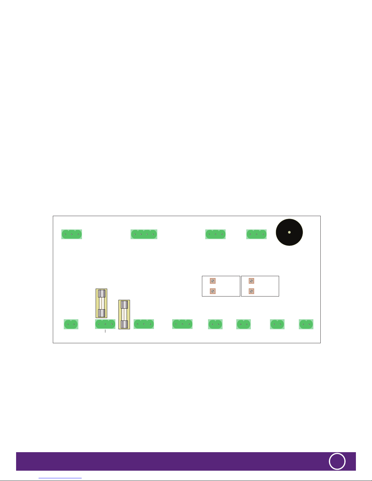
1. Unscrew the the front panel and turn it over. The panel PCB should resemble the diagram shown below.
2. Select the correct set of potentiometers for the sensor you are calibrating (Shown in diagram below) the set closer to the top
of PCB is for sensor 2 and set nearer bottom of PCB is for Sensor 1.
3. Using correct calibration gas (for your A1 low level alarm) immerse the sensor in the gas and after allowing the sensor time
to settle (10-20 seconds) adjust the A1 low alarm potentiometer (see diagram below) until the A1 LED on front of panel just
illuminates. If the A1 LED on front of ED510 is not illuminated rotate the potentiometer anti-clockwise to increase sensitivity. If the
light illuminates prematurely then decrease sensitivity by rotating potentiometer clockwise while repeatedly pressing the RESET
button on the ED510 front panel until the A1 LED goes out then turn slowly anti clockwise again until it just illuminates.
4. Repeat step 4 for the A2 high alarm calibration on the same sensor calibration with the following alterations:
i) Use the correct gas for your A2 high alarm
ii) Use the A2 potentiometer for sensor under gas concentration
iii) Use the A2 LED on the front of the ED510 panel to set calibration.
5. Repeat Step 2 to 4 if you have a second EDP sensor to calibrate.
LEVEL SWITCH CONNECTIONS
SEE PAGE 6
GAS SENSOR CONNECTIONS
SEE PAGE 7
VALVE CONNECTIONS
SEE PAGE 8
NON STANDARD
VALVE 1A MAX
EDL LOW
CONSUMPTION VALVE
FIRE DETECTOR CONNECTIONS
SEE PAGE 5
SOUNDER/BEACON
CONNECTIONS
SEE PAGE 7
POWER SUPPLY
INPUT 12V / 24V
+VE
FUSED OUT
-VE
+VE -VE
+VE S -VE
NO NC C NONCC NONCC+ - C NC
(BR) (G/Y) (BL) (BR) (G/Y) (BL)
+VE S -VE+VE -VE +VE -VE +VE -VE
LEVEL ZONE 1
RELAY OUTPUT
GAS VALVE
OUTPUT CONNECTIONSGENERAL ALARM
SOUNDER OUTPUT
1 AMP MAX GAS SENSOR 2GAS SENSOR 1
WATER LEVEL
ZONE 2
WATER LEVEL
ZONE 2
FIRE ZONE 1 FIRE ZONE 2
LEVEL ZONE 2
RELAY OUTPUT
DC INPUT / OUTPUT
VOLTAGE FREE CONTACTS
2A @30VDC NON INDUCTIVE
VOLTAGE FREE CONTACTS
2A @30VDC NON INDUCTIVE
SENSOR 2 CALIBRATION ADJUSTMENT
SENSOR 1 CALIBRATION ADJUSTMENT
A1 LOW
ALARM
A1 LOW
ALARM
A2 HIGH
ALARM
A2 HIGH
ALARM
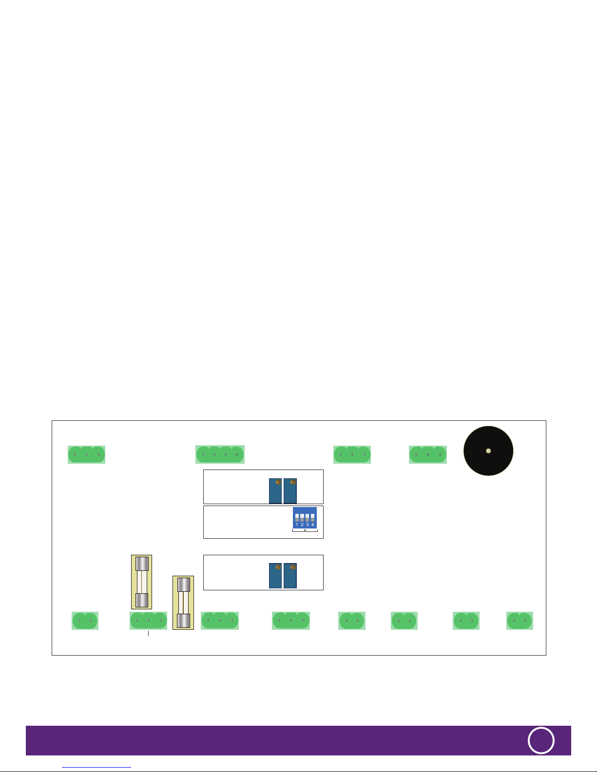
SEN1
SWITCH UP POSITION
(EDN HEAD ELECTRONICS 4C, 5C or 7C)
SWITCH DOWN POSITION
(EDP SEMICONDUCTOR 1B, 2B or 3B)
SEN2
ED510 - GAS DETECTOR ED510 IM REV 2 - 23.08.2017
12
CALIBRATION OF THE EDN TRANSMITTERS AND THE ED510
INITIAL SETUP
It is vitally important that the ED510 and EDN or P transmitters are calibrated together ensuring that the ED510 indicates an
alarm at the correct concentration. After installation is complete the following setup procedure should be followed matching the
EDN, ED510 and cable run together.
EDN CALIBRATION PROCEEDURE
1. Unscrew the the front panel and turn it over. The panel PCB should resemble the diagram shown below .
2. At EDN transmitter measure between -I/P and +I/P with a digital volt meter (See diagram above), ensure voltage reading is in
the range 4.75V and 5.4V.
3. Select the correct set of potentiometers for the sensor you are calibrating (Shown in diagram above) the set closer to the top
of PCB is for sensor 2 and set nearer bottom of PCB is for Sensor 1.
4. Using correct calibration gas for your A1 low level alarm ensure the calibration of the EDN transmitter using the EDN
calibration instructions.
5. Whilst the EDN is giving the correct output go to the ED510 control panel and adjust the A1 low alarm potentiometer (see
diagram below) until the A1 LED on front of panel just illuminates. If the A1 LED on front of ED510 is not illuminated rotate
the potentiometer anti-clockwise to increase sensitivity. If the light illuminates prematurely then decrease sensitivity by rotating
potentiometer clockwise while repeatedly pressing the RESET button on the ED510 front panel until the A1 LED goes out then
turn slowly anti clockwise again until it just illuminates.
6. Repeat step 4 for the A2 high alarm calibration on the same sensor calibration with the following alterations:
i) Use the correct gas for your A2 high alarm
ii) Use the A2 potentiometer for sensor under gas concentration
iii) Use the A2 LED on the front of the ED510 panel to set calibration.
7. Repeat Step 2 to 6 if you have a second EDN Head Electronics sensor to calibrate.
LEVEL SWITCH CONNECTIONS
SEE PAGE 6
GAS SENSOR CONNECTIONS
SEE PAGE 7
VALVE CONNECTIONS
SEE PAGE 8
NON STANDARD
VALVE 1A MAX
EDL LOW
CONSUMPTION VALVE
FIRE DETECTOR CONNECTIONS
SEE PAGE 5
SOUNDER/BEACON
CONNECTIONS
SEE PAGE 7
POWER SUPPLY
INPUT 12V / 24V
+VE
FUSED OUT
-VE
+VE -VE
+VE S -VE
NO NC C NONCC NONCC+ - C NC
(BR) (G/Y) (BL) (BR) (G/Y) (BL)
+VE S -VE+VE -VE +VE -VE +VE -VE
LEVEL ZONE 1
RELAY OUTPUT
GAS VALVE
OUTPUT CONNECTIONSGENERAL ALARM
SOUNDER OUTPUT
1 AMP MAX GAS SENSOR 2GAS SENSOR 1
WATER LEVEL
ZONE 2
WATER LEVEL
ZONE 2
FIRE ZONE 1 FIRE ZONE 2
LEVEL ZONE 2
RELAY OUTPUT
DC INPUT / OUTPUT
VOLTAGE FREE CONTACTS
2A @30VDC NON INDUCTIVE
VOLTAGE FREE CONTACTS
2A @30VDC NON INDUCTIVE
SENSOR 2 CALIBRATION ADJUSTMENT
SENSOR 1 CALIBRATION ADJUSTMENT
A1 LOW
ALARM
A1 LOW
ALARM
A2 HIGH
ALARM
A2 HIGH
ALARM
SEN1
SWITCH UP POSITION
(EDN HEAD ELECTRONICS 4C, 5C or 7C)
SWITCH DOWN POSITION
(EDP SEMICONDUCTOR 1B, 2B or 3B)
SEN2
ED510- GAS DETECTOR ED510 IM REV 2 - 23.08.2017
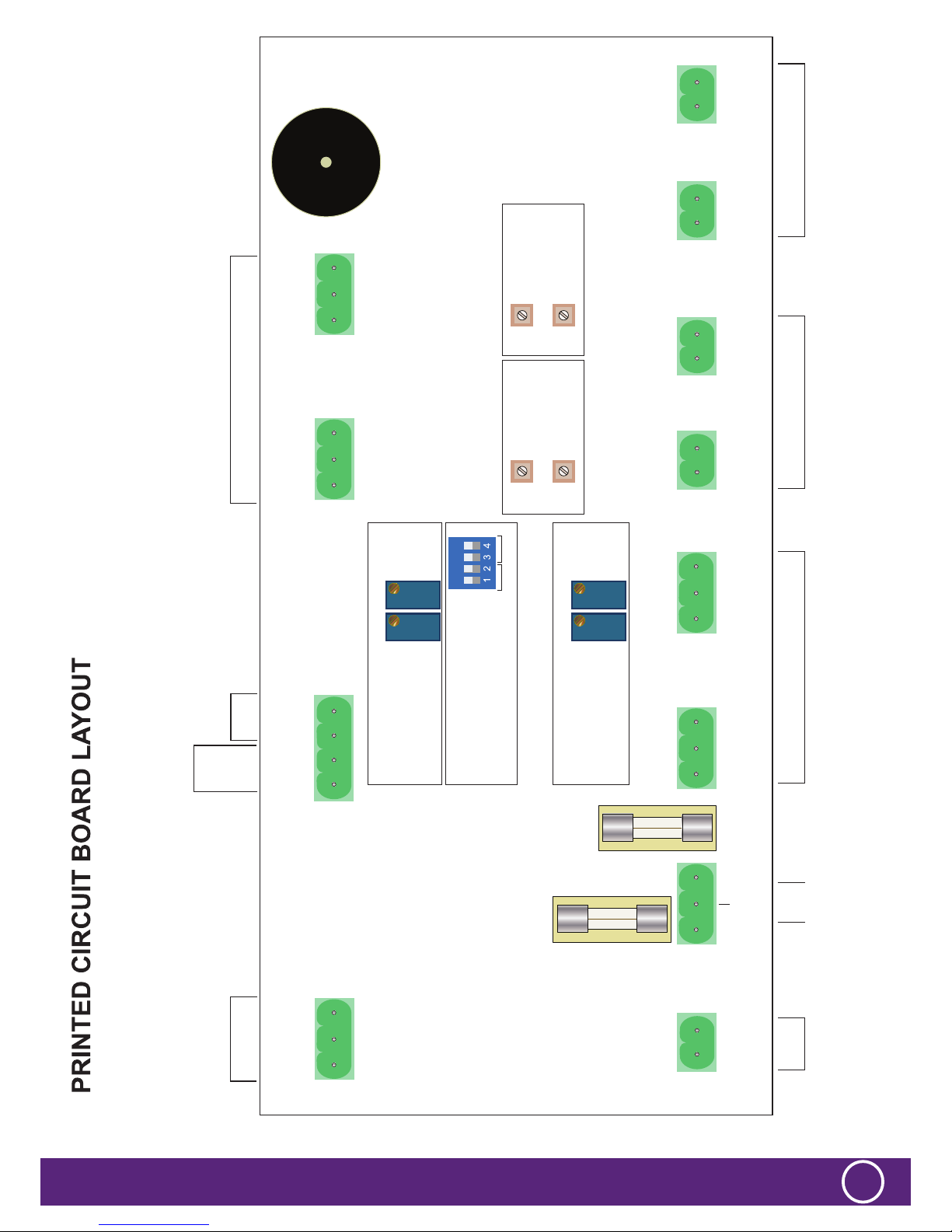
13
LEVEL SWITCH CONNECTIONS
SEE PAGE 7
GAS SENSOR CONNECTIONS
SEE PAGE 8
VALVE CONNECTIONS
SEE PAGE 9
NON STANDARD
VALVE 1A MAX
EDL LOW
CONSUMPTION VALVE
FIRE DETECTOR CONNECTIONS
SEE PAGE 6
SOUNDER/BEACON
CONNECTIONS
SEE PAGE 8
POWER SUPPLY
INPUT 12V / 24V
SENSOR 2 CALIBRATION ADJUSTMENT
SENSOR 1 CALIBRATION ADJUSTMENT
ON DELAY
ADJUST
A1 LOW
ALARM
A1 LOW
ALARM
A2 HIGH
ALARM
A2 HIGH
ALARM
ON DELAY
ADJUST
RUN-ON DELAY
ADJUST
RUN-ON DELAY
ADJUST
SEN1
+VE
FUSED OUT
-VE
+VE -VE
+VE S -VE
NO NC C NONCC NONCC+ - C NC
(BR) (G/Y) (BL) (BR) (G/Y) (BL)
+VE S -VE+VE -VE +VE -VE +VE -VE
SWITCH UP POSITION
(EDN HEAD ELECTRONICS 4C, 5C or 7C)
SWITCH DOWN POSITION
(EDP SEMICONDUCTOR 1B, 2B or 3B)
SEN2
VR3
VR6VR5
VR4
LEVEL ZONE 2LEVEL ZONE 1
LEVEL ZONE 1
RELAY OUTPUT
GAS VALVE
OUTPUT CONNECTIONSGENERAL ALARM
SOUNDER OUTPUT
1 AMP MAX GAS SENSOR 2GAS SENSOR 1
WATER LEVEL
ZONE 2
WATER LEVEL
ZONE 2
FIRE ZONE 1 FIRE ZONE 2
LEVEL ZONE 2
RELAY OUTPUT
DC INPUT / OUTPUT
VOLTAGE FREE CONTACTS
2A @30VDC NON INDUCTIVE
VOLTAGE FREE CONTACTS
2A @30VDC NON INDUCTIVE

ED510 - GAS DETECTOR ED510 IM REV 2 - 23.08.2017
14
108
238
452LENAPTNORF
TUOTUC TUOTUC
TUOTUC TUOTUC
7
7
7
FRONT PANEL 130
Table of contents
Other Electronic Devices Limited Security System manuals


