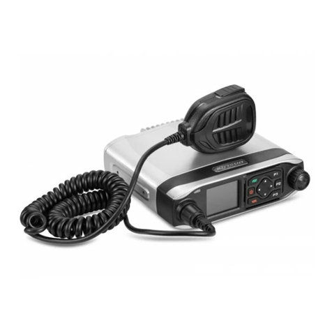
Electrophone TX-550 User manual

ELECTROPHONE
‘4.0
CHANNEL
Mobile 18-Channel
2-way CB radio
AM/SSB Deluxe
Model TX-550
Instruction Manual

General Description
Your TX-550 is an 18-channel AM/SSB CB transceiver,
skillfully constructed by employing the latest frequency
synthesizing technology.
The TX-550 features the following:
Compact, light weight, and suitable for mobile use.
Digital PLL frequency synthesizer.
Clarifier.
Noise blanker and noise limiter incorporated.
Compatible with three modes of operation, LSB, USB, or
AM.
Lighted S/RF meter.
Digital LED channel readout.
Capable of public address operation.
Reversible ground polarity.
External speaker jack.
Deluxe detachable microphone.
All mounting brackets and hardware included.
Warranty
Standard Components Pty. Limited warrants this
product to be free from defects in material and
workmanship for a period of ninety days from the
date of purchase.
We reserve the right to determine whether damage has
been occassioned by accident, misuse or improper
installation whereby the warranty would be void.
For under warranty service the equipment should be
returned to your supplier with a full description of the
fault. Only authorised service agents will be authorised
to repair equipment under warranty and these charges
would be accepted by the distributor.
Retailers or Suppliers who do not have an authorised
service section must return this equipment to Standard
Components Pty. Limited for under-warranty service.
If any authorised repair work has been attempted on
the equipment, the guarantee will be void.
All equipment returned to the distributor for under
warranty must be sent freight pre-paid.
Standard Components Pty. Limited reserves the right
not to repair or replace during the under-warranty
period free of charge output transistors which may
have been damaged due to incorrect aerial installation.

Technical Specification
General
Frequency.
27.015 to 27.225 MHz.
Channels.
18.
Frequency Tolerance.
±0.005%.
Channel Composition.
PLL [phase-locked-loop]
synthesizer.
Operating Temperature Range.
—30
°
C to +50
°
C.
Power Supply.
13.8 volts DC, negative or positive
ground.
Mode of Operation.
LSB, USB, AM.
Receiver
System.
SSB. Single conversion superheterodyne.
AM. Dual conversion superheterodyne.
Sensitivity.
SSB. 0.25 microvolt for 10 dB S/N.
AM. 1 microvolt for 10 dB S/N.
Selectivity.
SSB. 2 kHz at 6 dB down.
AM. 6 kHz at 6 dB down.
Clarifier.
±800 Hz range.
Audio Output.
3 watts at 8 ohms.
Squelch Range.
SSB. 0.7 to 500 microvolts. AM. 1 to
500 microvolts.
F.
SSB. 10.695 MHz. AM. 1st; 10.695 MHz,
2nd; 0.455 MHz.
SSB Transmitter
Generation.
Double balanced modulator with crystal
latice filter.
RF Output Power.
12W PEP at 13.8V DC.
Carrier Suppression.
More than 40 dB down.
Unwanted Side Band Suppression.
More than 60 dB
down.
Harmonic Suppression.
More than 60 dB down.
AM Transmitter
RF Output Power.
4W at 13.8V DC.
Harmonic Suppression.
More than 60 dB down.
Modulation.
High level class B.

5111111.:1111
11
"""m"
Microphone Jack
Off/Volume Control-
Squelch Contro
-Channel Selector
-LSB/USB/AM Mode Selector
PA Jack (3.5 mm)-
External Speaker Jack (3.5 mm)-
,
-ANL Switch
NB Switch-
-CB-PA Switch
RF/S Meter-
-Channel Readout
-Antenna Connector (S0-239)
DC Power Socket (13.8V DC)-
4

Control Functions
RF/S Meter.
When receiving this gives the relative signal
strength of incoming signals; when transmitting RF
power output.
Clarifier Control.
If a station received is not clear during
AM reception, adjust this control for maximum S meter
indication. During SSB reception, rotate this control so
that the received signal sounds intelligible.
Channel Indicator.
An LED digital readout to show the
channel you desired. Turned off when operating the PA.
Channel Selector.
Selects one of 18 channels.
CB-PA Switch.
Your radio has been equipped with a
PA (Public Address) amplifier system. Setting this
switch to PA position actuates the PA system. Press
the push-to-talk bar on the microphone and speak
at a normal tone of voice, then your voice will be heard
through the PA speaker connected to the PA SP jack
on the rear panel. For normal CB operation, place the
switch in CB position.
Squelch Control.
Turn the knob clockwise until
background noise disappears. Now you can hear signals
without annoying background noises. Rotating the
Squelch too far clockwise direction decreases reception
sensitivity, and very weak station would not be received.
Therefore, when you are in communication with a
distant or weak station, rotate the Squelch all the way
counterclockwise.
Volume Control/Power Switch.
Turns the power on and
controls the sound output from the speaker.
LSB/USB/AM Switch.
Selects a mode of operation --
LSB, USB, or AM.
NB Switch.
If you encounter the impulse type noise
interference, place this in NB position.
ANL Switch.
Place in On (ANL) position if you
encounter atmospheric noise interference.
DC Power Connector.
Used for connecting the DC
power cord supplied. See 'DC Power Connection'
instructions. Do not force the DC power cord plug
onto the pins. Align it properly to insert the connector.
PA SP Jack.
Used for connecting the PA speaker
(impedance: 8 to 16 ohm). Matches 3.5 mmo standard
type phone plug. Insertion of an external speaker into
this jack will automatically silences the built-in speaker.
Antenna Connector.
Used for connecting the antenna
and matches PL-259 type coaxial plug.
5

Mounting Instruction
First choose a location to be mounted. The location
should be a place where is convenient to use the
transceiver, and does not interfere with the driver.
Usually, the underside of the instrument panel or
dashboard of a vehicle will be selected. A special
bracket for this purpose is supplied with the unit.
1
Drill three or four holes (diameter: about 3.6 mm or
1/8") to the location to be mounted.
2
Attach the bracket, using self-tapping screws and
washers supplied.
3
A microphone hanger is also supplied with the unit.
If necessary attach the bracket on a place close to the
transceiver, using two screws included.
4
Secure the transceiver to the bracket by means of the
large thumb screws and washers supplied.
DC Power Connection
This transceiver is designed to be operated from 12 volts
DC battery, on either negative or positive ground system.
Power Connection for Negative Ground System.
1
Connect the
black
lead from the transceiver to the
metal chassis ground of the vehicle or
negative
battery
terminal.
2
Connect the
red
lead from the transceiver to any
convenient hot
(positive)
side of the electrical system or
plus (+)
battery terminal.
Power Connection for Positive Ground System.
1
Connect the
red
lead from the transceiver to the
metal chassis ground of the vehicle or
positive
battery
terminal.
2
Connect the
black
lead from the transceiver to any
convenient hot
(negative)
side of the electrical system
or
minus (—)
battery terminal.
If you can not determine the electrical polarity in your
vehicle, consult with your car dealer. However, when
you can not obtain the necessary information, directly
connect the
red
lead to the
plus (+)
battery terminal
and the
black
lead to the
minus (—)
battery terminal, to
avoid damaging the transceiver.
6

Antenna Connection
Warning.
Before operating your transceiver, you must
connect a proper antenna system. Operating the
transceiver without an antenna or dummy load may
cause damage to the expensive RF power transistors.
The antenna is one of the most important factors in the
operation of the transceiver with its full efficiency. An
improper antenna may decrease reception sensitivity
and lower the communication range. The CB antenna
and its mounting method will largely depend upon the
type of your vehicle, mounting position, etc. Also, the
antenna may be different according to your needs —
using your transceiver as a mobile or base station
transceiver. We recommend you to consult with the
dealer from which you purchased the transceiver or
any other CB/amateur radio equipment supply shop.
They will meet your specific needs.
Operating Instruction
Make sure your antenna system is connected to the
antenna connector on the rear panel. Do not operate
the transceiver without the antenna.
AM Reception
1
Connect the push-to-talk microphone to the mic jack.
2
Place the C B-PA switch to CB.
3
Turn the power on and rotate the Volume control to
increase the sound level.
4
Rotate the Squelch control to 9 o'clock position.
5
Place the LSB/USB/AM switch in the AM position.
6
Select the channel you desire.
To transmit: Depress the push-to-talk button on the
microphone and speak into the microphone at a normal
voice, holding the microphone 3 to 6 inches from the
mouth. Do not shout or move the microphone too close
to your mouth.
To receive: Simply release the push-to-talk button.
7
Adjust the clarifier control for clearer reception.
7

SSB Reception
1
Turn the power on and rotate the Volume control to
a proper sound level.
2
Place the LSB/USB/AM switch in the LSB or USB
position in which clearer voice reception is obtained.
If you want to communicate with the station
transmitting in LSB mode, your transceiver must be set
in the same mode (LSB) of operation. This also applys
to USB operation. Then adjust the clarifier control
slowly for clearest voice reception.
Transmission
1
To transmit depress the push-to-talk button on the
microphone and speak at the microphone.
2
To receive, simply release the push-to-talk button.
Interference Noises
During reception, you may find that your transceiver will
pick up interference noises which make the reception of
weaker stations difficult. The most common source of
these noises is the ignition system of your own vehicle,
since your transceiver is placed relatively close to your
ignition system (engine). In such a case, we recommend
you to consult with your car dealer to eliminate the
ignition noise. Usually the ignition noise will be
suppressed considerably by using a proper radio
suppression type high voltage ignition wire and suppressor
resistor in the ignition system. (Most vehicles are
equipped with this wire and resistor, but it may be
necessary to check them for correct operation). Another
method to suppress the noises is to use additional noise
suppressor which is available at your local CB radio
shops.
8

AUSTRALIAN 40/18 CHANNEL CONVERSION CHART
40
Ch. Frequency
18
Ch. Suggested Usage
40
Ch.
Frequency
18
Ch. Suggested Usage
1
26.965 MHz.
-
General A.M.
20
27.205 MHz.
17
General SSB.
2
26.975 MHz.
-
,,
,,
21
27.215 MHz.
-
3
26.985 MHz.
II
II
22
27.225 MHz.
18
,,
4
27.005 MHz.
-
,,
23
27.255 MHz.
-
II
5
27.015 MHz.
1
II
24
27.235 MHz.
-
II
6
27.025 MHz.
2
II
25
27.245 MHz.
-
II
7
27.035 MHz.
3
II
II
26
27.265 MHz.
-
8
27.055 MHz.
4
"
"
(3)
27
27.275 MHz.
-
9
27.065 MHz.
5
Emergency Channel (1)
28
27.285 MHz.
-
10
27.075 MHz.
-
General A.M.
29
27.295 MHz.
-
11
27.085 MHz.
6
Call Channel A.M. (1)
30
27.305 MHz.
-
-
27.095 MHz.
7
General A.M.
31
27.315 MHz.
-
12
27.105 MHz.
8
II
II
32
27.325 MHz.
-
II
13
27.115 MHz.
9
II
"
33
27.335 MHz.
II
14
27.125 MHz.
10
,,
34
27.345 MHz.
II
II
15
27.135 MHz.
11
,,
35
27.355 MHz.
-
II
"
(2)
16
27.155 MHz.
12
Call Channel S.S.B. (1)
36
27.365 MHz.
-
II
II
17
27.165 MHz.
13
General SSB.
37
27.375 MHz.
-
18
27.175 MHz.
14
38
27.385 MHz.
-
19
27.185 MHz.
15
II
II
39
27.395 MHz.
_
II
-
27.195 MHz.
16
40
27.405 MHz.
-
1. Legally Designated.
2. Suggested 2nd SSB Call Channel.
3. Suggested Road Channel.
License
Requirements
It is necessary for a person operating a citizen band
radio to obtain a license for an equipment. There is a
license fee per annum for each unit.
Applications for licenses should be lodged at any of the
Postal and Telecommunications Department's State and
District offices.
It will be necessary to advise:
(1)
Name and address of lincensee,
(2)
Make,
(3)
Model and Serial No.
and pay the fee in order to obtain the license.
The license No. will also be the call sign.
For service on this equipment please first contact your
local retailer.
Full service and spare parts supplies are available to
your retailer through the Distributor:
Standard Components Pty. Limited,
10 Hill Street, Leichhardt. NSW.
9

Schematic Diagram

KTTX550*AX
Printed in *on

