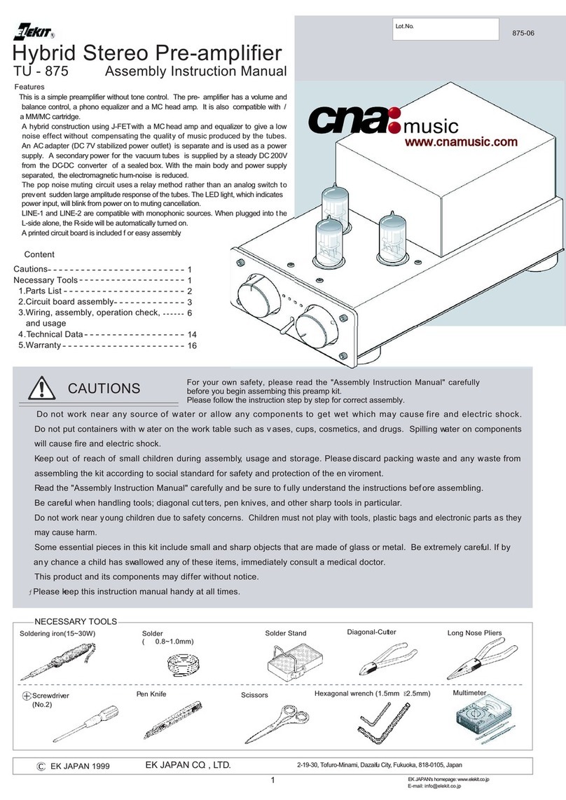
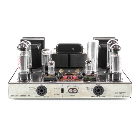
Elekit 6L6GC Installation guide

© EK Japan 2005
TubeDepot.com
6L6GC Single Stereo Tube Po er Amp
TU-
879S Assembly Instruction Manual
Features:
This is a single stereo po er amplifier using the po erful 6L6GC.
Assembly is easy. Anyone can follo the printed circuit board and
obtain the same result. For this reason, you do not need to kno the
details of iring and other technical details to assemb
tube amplifier kit.
This amplifier is compact and po erful enough to surpass the capacity
of output transformers in other models under the same class of our
company (TU-
877, 874, etc.). This amplifier includes premium
capacitors hich enhance sound quality.
This amplifier uses improved MOS FET regulated ripple filtering
driver tube heater is po ered from a DC supply ith a 2mm thick
shielded panel added to effectively reduce hum noise to
Additionally, a number of other compo
nents have also been upgraded.
Content
Cautions …………………………………………….…… 1
Necessary Tools …………………………………….. 1
1. Parts list ……………………………………………… 2
2. Circuit Board Assembly ………………………. 3
CAUTIONS
========================
♦Do not ork near any source of ater
or allo any components to get et hich may cause fire and electric shock.
♦
Do not put containers ith ater on the ork table such as vases,
fire and electric shock.
♦
Keep out of reach of small children during assembly, usage and storage. Please discard packing aste and any aste from assem
kit according to social sta
ndard for safety and protection of the environment.
•
Read the “Assembly Instruction Manual” carefully and be sure to fully understand them before assembling.
•
Be careful hen handling tools; diagonal cutters, pen knives, and other sharp tools in particular.
•
Do not ork near young children due to safety concerns. Children must not play ith tools, plastic bags and electronic parts
cause harm.
•
Some essential pieces in this kit include small and sharp objects that are made of glass or metal. Be extre
child has s allo ed any of these items, immediately consult a medical doctor.
•
This product and its components may differ ithout notice.
Please keep this instruction manual handy at all times.
NECESSARY TOOLS
It is handy but not necessary
For your own safety, please read the “Asse bly Instruction Manual”
carefully before you begin asse bling the Power A plifier Kit.
Please follow the instructions step by
Soldering Iron (15
-
30W)
Solder (
φ
0.8-1.0mm)
Nut Driver (5.5mm)
Hexagonal Wrench
(1.5mm-2.5mm)
TubeDepot.com
info@tubedepot.com
1686 Barcrest Drive, Memphis, TN 38134
6L6GC Single Stereo Tube Po er Amp
879S Assembly Instruction Manual
This is a single stereo po er amplifier using the po erful 6L6GC.
Assembly is easy. Anyone can follo the printed circuit board and
obtain the same result. For this reason, you do not need to kno the
details of iring and other technical details to assemb
le this vacuum
This amplifier is compact and po erful enough to surpass the capacity
of output transformers in other models under the same class of our
877, 874, etc.). This amplifier includes premium
This amplifier uses improved MOS FET regulated ripple filtering
. The
driver tube heater is po ered from a DC supply ith a 2mm thick
shielded panel added to effectively reduce hum noise to
a minimum.
nents have also been upgraded.
3. Wire harn
ess, chassis assembly and usage
4. Technical Data …………………………………
…
5. Vacuum Tube …………………………………
…
6. Warranty ………………………………………
…
or allo any components to get et hich may cause fire and electric shock.
Do not put containers ith ater on the ork table such as vases,
cups, cosmetics, and drugs. Spilling ater on components ill cause
Keep out of reach of small children during assembly, usage and storage. Please discard packing aste and any aste from assem
ndard for safety and protection of the environment.
Read the “Assembly Instruction Manual” carefully and be sure to fully understand them before assembling.
Be careful hen handling tools; diagonal cutters, pen knives, and other sharp tools in particular.
Do not ork near young children due to safety concerns. Children must not play ith tools, plastic bags and electronic parts
Some essential pieces in this kit include small and sharp objects that are made of glass or metal. Be extre
mely careful. If by any chance a
child has s allo ed any of these items, immediately consult a medical doctor.
This product and its components may differ ithout notice.
Please keep this instruction manual handy at all times.
Pen Knife
For your own safety, please read the “Asse bly Instruction Manual”
carefully before you begin asse bling the Power A plifier Kit.
Please follow the instructions step by
step for correct asse bly.
Solder Stand
Diagonal Cutter
Long Nose Pliers
Scissors
Oil based marker
(fine point)
1686 Barcrest Drive, Memphis, TN 38134
1
ess, chassis assembly and usage
………. 8
…
………………. 18
…
……………… 19
…
……………….. 20
or allo any components to get et hich may cause fire and electric shock.
cups, cosmetics, and drugs. Spilling ater on components ill cause
Keep out of reach of small children during assembly, usage and storage. Please discard packing aste and any aste from assem
bling the
Read the “Assembly Instruction Manual” carefully and be sure to fully understand them before assembling.
Do not ork near young children due to safety concerns. Children must not play ith tools, plastic bags and electronic parts
as they may
mely careful. If by any chance a
Long Nose Pliers
⊕
Scre Driver
(No. 1 and No.2)
Oil based marker
Optional-voltage and
connection check is suggested
Multimeter
www.cnamusic.com

© EK Japan 2005
TubeDepot.com
Before you solder, follo the cut line (grooved line) to break the circuit boards TU
There are grooved lines on both sides of the circuit board. Gently use the
2. Circuit Board Assembly
A Circuit Board Assembly
Preparations before you begin
On the soldering side (side ith copper foil) of circuit board
Solder plate the 2 holes ith copper foils.
SG (2 places)
/
The line is on the side of K
D1
Marked on PCB
Ho to install
Resistor
R1,9,10,11,
R3,4,25,25 2k
R5,6,23 3.3
R7,8,15 120
R20,21,22 2.2M
Resistor
R16,18,19
R13,14 330
R17 3.3k
Marked
+,- indication
\
D2, 3
Marked on PCB Ho to install
Marked
Ho
C7, 8
220pF ( ith indication of 221)
Marked on PCB
Ho to install
Install from solder side (reverse side), total of 12
OPT1(L) P 3 pcs
OPT1(L) B 3 pcs
OPT2(R) P 3 pcs
OPT2(R) B 3 pcs
Install from the side ith
FET G, D, S
Marked
Where the fuse holder (metal
fitting) is placed, please
a thick layer of solder plate on the
oval shaped copper foil.
1.
Diode (direction specific)
5
. Fuse holder
4
. Bridge Rectifier
(direction specific)
Please pay attention! It is
dangerous if the rectifier is not
installed properly.
Bend the legs on the back of the PCB
to prevent it from falling out hen
soldering on the copper foil.
6
. Ceramic Capacitor
(non direction specific)
7
. Base pin
Before you solder
Follo the instructions step
have soldered each component.
When soldering, be sure to read “The Key to Soldering.”
TubeDepot.com
info@tubedepot.com
1686 Barcrest Drive, Memphis, TN 38134
Install the metal oxide
film resistor 2-3mm above
the PCB to diffuse heat.
Before you solder, follo the cut line (grooved line) to break the circuit boards TU
-879R A-
E into individual pieces.
There are grooved lines on both sides of the circuit board. Gently use the
edge of a table to break them.
On the soldering side (side ith copper foil) of circuit board
A, there are 3 holes ith arro s indicated.
SG (2 places)
Resistor
(Carbon)
R1,9,10,11,
12 330kΩ
(Orange, Orange, Yello , Gold)
R3,4,25,25 2k
Ω
(Red, Black, Red, Gold)
R5,6,23 3.3
Ω
(Orange, Orange, Gold, Gold)
R7,8,15 120
Ω
(Bro n, Red, Bro n, Gold)
R20,21,22 2.2M
Ω
(Red, Red, Green, Gold)
Resistor
(metal oxide film)
R16,18,19
15kΩ(2W)
R13,14 330
Ω(3W)
R17 3.3k
Ω(5W)
Marked
on PCB Ho to install
Marked on
PCB
Ho to install
(1)
Cut 7 strands of tin
(2)
Put a strand of tin
and bend to
the shape in the image belo . The
total length of the product should be 35mm. Use
long nose pliers to bend.
(not actual size)
(3)
Solder the jumper ires onto the PCB the same ay as the resistors
Marked
on PCB
Ho
to install
Install from solder side (reverse side), total of 12
OPT1(L) P 3 pcs
OPT1(L) B 3 pcs
OPT2(R) P 3 pcs
OPT2(R) B 3 pcs
Install from the side ith
hite printing, total of 3
FET G, D, S
Marked
on PCB (FET only)
Where the fuse holder (metal
fitting) is placed, please
pre-apply
a thick layer of solder plate on the
oval shaped copper foil.
2
.
Resistor
(non-direction
3
.
Jumper ire
Carbon
resistor
. Fuse holder
(direction specific)
. Base pin
FUSE 1, 2
Follo the instructions step
-
by
-
step. Check off the box after you
have soldered each component.
When soldering, be sure to read “The Key to Soldering.”
Set the
5x20 GMA fuse
to t o fuse holders
and put the legs through the hole
s on the PCB
from the solder side.
Bend the legs using long nose pliers to
station it on the PCB. Take the
5X20 GMA
from the fuse holder and solder the fuse
holders onto the copper foil.
Reinstall the 5X20 GMA
fuse after soldering.
FUSE1 →0.3A FUSE2 →
2A
Caution: 12 pins are installed from the solder side ( ith copper foil)
and 3 pins are installed from the side ith hite printing.
Marked on PCB
Insert the pin
perpendicularly into
the hole on the PCB.
Al ays solder on the
solder side (reverse
side) regardless of
hich side the pin is
inserted from.
1686 Barcrest Drive, Memphis, TN 38134
3
E into individual pieces.
J1
-
7
PCB
Cut 7 strands of tin
-coated ire 6-7cm in length.
Put a strand of tin
-coated ire into a plastic tube
the shape in the image belo . The
total length of the product should be 35mm. Use
long nose pliers to bend.
Solder the jumper ires onto the PCB the same ay as the resistors
Jumper ire
(non-direction specific)
to t o fuse holders
s on the PCB
Bend the legs using long nose pliers to
5X20 GMA
fuse
from the fuse holder and solder the fuse
fuse after soldering.
2A
Caution: 12 pins are installed from the solder side ( ith copper foil)
and 3 pins are installed from the side ith hite printing.
Al ays solder on the
Put the PCB on a
piece of cardboard
hen installing the
pins. Use long nose
pliers to insert the pin.
Do not cut the
protruding base pin
after soldering.
This manual suits for next models
1
Other Elekit Amplifier manuals
