Elekta Neuromag User manual

Elekta Neuromag®
System Hardware
Technical manual
Revision F
September 2005
Elekta Neuromag

2 NM20216A-F
© Copyright Elekta Neuromag Oy, Helsinki, Finland 2005
This document contains copyrighted and possibly confidential information and is intended for the exclusive use of
customers having Elekta Neuromag products and authorized representatives of Elekta Neuromag Oy. Disclosure
to others or other use is strictly prohibited without the express written authorization of Elekta Neuromag Oy.
Elekta Neuromag Oy reserves the right to make changes in the specifications or data shown herein at any time
without notice or obligation.
Elekta Neuromag Oy denies any responsibility for damage to apparatus or persons due to improper use or service
performed by unauthorized persons. Elekta Neuromag Oy assumes no liability for damage and/or failure of
equipment caused by faulty site preparation.
Elekta Neuromag is a trademark of Elekta. The system has been marketed and sold previously under the name
Neuromag Vectorview (also a trademark of Elekta). All other product names or other company names used herein
are for identification purpose only and may be trademarks or registered trademarks of their respective owners.
All rights reserved. Reproduction in any form without the written permission of Elekta Neuromag Oy is
strictly prohibited.
Printing history Neuromag p/n Date
First edition NM20216-4A 3.6.1998
First revised edition NM20216-4A-1 10.7.1998
Second edition NM20216-4A-2 2.10.1998
Third edition NM20216-4A-3 20.10.1998
Fourth edition (Rev. D) NM20216A-D 7.7.1999
Fifth edition (Rev. E) NM20216A-E 1.2.2005
Sixth edition (Rev. F) NM20216A-F 23.5.2005
- errata included in text NM20216A-F 30.9.2005

NM20216A-F 3
Contents
List of symbols 5
Chapter 1 Technical data 7
1.1. The probe unit ................................................................................................ 7
1.1.1. General ..................................................................................... 7
1.1.2. Sensors ..................................................................................... 7
1.1.3. Probe unit construction ............................................................. 8
1.1.4. Dewar ........................................................................................ 8
1.2. Gantry, bed, and chair .................................................................................... 9
1.2.1. Gantry ....................................................................................... 9
1.2.2. Bed ............................................................................................ 9
1.2.3. Chair........................................................................................ 10
1.3. MEG and EEG Electronics ........................................................................... 10
1.3.1. General ................................................................................... 10
1.3.2. MEG preamplifiers .................................................................. 11
1.3.3. EEG preamplifiers ................................................................... 11
1.3.4. Electrode interface .................................................................. 12
1.3.5. Filter unit ................................................................................. 13
1.3.6. MEG main electronics ............................................................. 14
1.3.7. EEG main electronics.............................................................. 15
1.4. MEG and EEG Power Supplies .................................................................... 15
1.4.1. Front-end MEG power supply ................................................. 15
1.4.2. Front-end EEG power supply (isolated) .................................. 16
1.4.3. MEG and EEG electronics power supply unit ......................... 16
1.4.4. Real-time data acquisition computer power supply ................. 16
1.4.5. Main iIsolation transformers .................................................... 17
1.5. Filter Unit Cabinet and Electronics Cabinet.................................................. 17
1.5.1. Filter unit cabinet ..................................................................... 17
1.5.2. MEG Electronics cabinet ......................................................... 17
1.6. Auxiliary electronics ...................................................................................... 18
1.6.1. Head Position Indicator (HPI) .................................................. 18
1.6.2. 3D digitizer .............................................................................. 18
1.6.3. Phantom .................................................................................. 18
1.6.4. Phantom current driver / multiplexer ....................................... 18
1.6.5. Liquid Helium level gauge and display .................................... 19
1.6.6. Stimulus cabinet ...................................................................... 19
1.6.7. Audio electronics interface ...................................................... 19
1.6.8. Thermometer sensors (for maintenance only) ........................ 20
1.6.9. Voice intercom (option) ........................................................... 20
1.6.10. Video monitor (option) ............................................................. 20

4 NM20216A-F
1.7. Data Acquisition System Hardware .............................................................. 20
1.7.1. Real-time data acquisition computer system .......................... 20
1.7.2. Stimulus I/O interface unit ....................................................... 20
1.8. Computer system hardware ......................................................................... 21
1.9. Helium transfer equipment ........................................................................... 22
1.10. Environmental and power requirements, grounding ..................................... 22
1.11. Classification (IEC 60601-1-1) ..................................................................... 23
1.12. Miscellaneous ............................................................................................... 23
1.13. Options ......................................................................................................... 24
1.14. Electromagnetic compatibility (EMC) ........................................................... 25
1.14.1. General ................................................................................... 25
1.14.2. List of cables, transducers and other accessories .................. 25
1.14.3. Guidance and manufacturer’s declaration ............................... 26
1.15. Final disposal ............................................................................................... 30
Chapter 2 Dimensions and weights 31
2.1. Dewar dimensions ........................................................................................ 31
2.2. Gantry and chair dimensions........................................................................ 33
2.3. Dimensions of cabinets ................................................................................ 35
2.4. Table of dimensions and weights.................................................................. 36
Chapter 3 Diagrams 37
3.1. Electronics diagrams .................................................................................... 37
3.1.1. System diagrams .................................................................... 37
3.1.2. EEG electronics ...................................................................... 39
3.1.3 Auxiliary electronics ................................................................ 41
3.1.4 Lifting mechanism ................................................................... 42
3.2. Electronics cabinets ..................................................................................... 43
3.2.1. Main electronics cabinets ........................................................ 43
3.2.2. Stimulus cabinet ...................................................................... 45
3.3. Power supplies ............................................................................................. 47
3.3.1. Schematic diagram ................................................................. 47
3.3.2. Recommended power and grounding arrangement ................ 48
3.4. Probe unit ..................................................................................................... 49
3.4.1. Gradiometer chip and sensor array ......................................... 49
3.4.2. Cryogenic insert ...................................................................... 50
3.6. Data acquisition software block diagram ...................................................... 51
Appendix 53
Additional site-specific data sheets (if applicable) ........................................ 53

NM20216A-F 5
List of symbols
The following symbols are used in the system and in the manuals. Familiarize yourself
with each symbol and its meaning before operating this system.
Caution, consult accompanying documents. Parts of the system are marked with this
symbol when it is necessary for the user to refer to important operating and mainte-
nance instructions given in the manuals accompanying the system. In the manuals, it
also calls attention to specific instructions. These instructions may contain procedures,
practices, conditions or the like which must be correctly performed or adhered to in
order to ensure safe operation and to avoid damage to the patient, operator, or the system.
Consult instructions for use. Parts of the system are marked with this symbol when it
is necessary for the user to refer to important operating and maintenance instructions
given in the manuals accompanying the system. In the manuals, it also calls attention
to specific instructions. These instructions may contain procedures, practices, condi-
tions or the like which must be correctly performed or adhered to in order to ensure
correct operation and/or increased safety and to avoid damage to the system.
Type BF (body floating) equipment symbol. The applied parts (parts in direct contact
with the person being investigated with the system) and the type plate are marked with
this symbol to indicate that they fulfill the leakage current requirements of the safety
standard IEC 60601-1).
Alternating current (power line) symbol.
On (power line) symbol.
Off (power line) symbol.
Protective ground (earth) terminal symbol. Used to identify terminals which are intended
for connection to an external protective conductor for protection against electrical shock in
case of a fault, or to the terminal of a protective ground (earth) electrode.
Static electricity symbol. The parts of the system marked with this symbol indicate the
presence of components susceptible to static electricity and require the use of antistatic
techniques. See Elekta Neuromag System Hardware: User’s Manual.
Magnetic objects and devices symbol. The use of these symbols in the vicinity of the
probe unit indicate that magnetic objects or devices may cause disturbances in the
operation of the system; they should therefore be avoided. See Elekta Neuromag
System Hardware: User’s Manual
Non-ionizing radiation, RF transmitter. Marking on equipment or equipment parts that
include RF transmitters or that intentionally apply RF electromagnetic energy.
Separate collection of waste electrical and electronics equipment (WEEE) necessary
(European Union directive 2002/96/EC on WEEE)
Date of manufacture: year (four digits) followed by month
SN
11

6 NM20216A-F

NM20216A-F 7
CHAPTER 1 Technical data
1.1. The probe unit
1.1.1. General
• Number of MEG channels: 306 channels
• Sensor coverage: whole cortex, 1220 cm2
• Measurement positions: supine, upright
• Minimum room height required: 2.3 m
• Dimensions and weights: see chapter 2
1.1.2. Sensors
• Type of sensors: 102 identical plug-in triple-sensor-units with two
orthogonal planar gradiometer flux transformers, one magnetometer
flux transformer, and three dc-SQUIDs (Superconducting Quantum
Interference Devices).
• Field components: Bz, ∂Bz/∂xand ∂Bz/∂y
• Sensor distance from the outside helmet surface of the dewar: average
18 mm
• Material and construction of dc SQUIDs: all-refractory thin-film
structures on silicon
• Average triple-sensor-unit spacing: 34 mm
• Size of gradiometers and magnetometers: 28 mm ×28 mm
• Type of SQUIDs: dc SQUIDs
• Material and construction of gradiometers and magnetometers: all-
refractory thin-film structures on silicon
• Base length of gradiometers: 17.0 mm
• Effective total surface area of each oppositely wound gradiometer
coil: 2.7 cm2 and for the magnetometer coils 7.6 cm2.
• RF interference suppression: integrated RC-shunts.
• Low frequency interference suppression: with hardware and compu-
tational compensation.
• Integrated heater elements for de-trapping.
• Balance: better than 10-3 for gradiometers.
1

8 NM20216A-F
1Technical data
Noise performances for all operational channels are the following:
• Gradiometer noise (white noise, 60Hz < f < 70Hz): max. 5 fT/(cm
Hz
) for 96% of channels, max. 10 fT/(cm
Hz
) for all gradiometer
channels
• Magnetometer noise (white noise, 60Hz < f < 70Hz): max. 5 fT/
Hz
for 96% of channels, max. 10 fT/
Hz
for all magnetometer channels
• Gradiometer noise (low frequency, 1Hz < f < 2Hz); max. 12 fT/(cm
Hz
) for 96% of channels, max. 20 fT/(cm
Hz
) for all gradiometer
channels
• Magnetometer noise (low frequency, 1Hz < f < 2Hz); max. 12 fT/
Hz
for 96% of channels, max. 20 fT/
Hz
for all channels
1.1.3. Probe unit construction
• Wiring unit: printed circuit board plates, a flexible support tube and a
support shell onto which the triple sensor elements are mounted with
connectors. Twisted pairs between the dc-SQUIDs and the printed
circuit boards on the top of the wiring unit where the components for
the dc-SQUID gain control reside.
• Connection wiring: flexible cable assembly from the printed circuit
boards to the top flange
• Top flange: preamplifiers and connectors for the cables to the elec-
tronics unit
• liquid He-level probe: integrated, superconducting
• Helium siphon: fixed, connects to a flexible part used in transfers
• Thermometers: two Pt-thermometers for monitoring the cool-down
and warm-up of the system
1.1.4. Dewar
• Lower end: helmet-shaped
• Shape of the helmet is based on the EN960:1994 standard
• Circumference of helmet outside surface: 629 mm
• Maximum length of the helmet opening: 222 mm
• Maximum width of the helmet opening: 181 mm
• Maximum inside height of the helmet: 210 mm
• Distance from the surface at liquid helium to the outer room temper-
ature surface against the subject’s head: typically 18 mm
• Thermal radiation shielding: superinsulation and a thermally an-
chored shield
• Material of construction: fiberglass composite
• Total volume of Helium 78 liters

NM20216A-F 9
Technical data 1
• Boiloff rate of liquid Helium: max. 8 liters per 24 hours
• Exhaust of Helium gas due to liquid Helium boiloff (+20 °C, normal
operation at atmospheric pressure): typ. 4 liters per minute
• Helium transfer equipment: see 1.9 below
• Monitoring of the liquid Helium level: integrated sensor and readout
electronics
• Separate local liquid Helium level display integrated inside the gantry
for follow-up during the transfer
• Automatic helium level data gathering to the computer system
• Relief valve opening pressure: 10 kPa (0.1 bar)
• Safety exhaust rupture pressure: 60 kPa (0.6 bar)
• Safety exhaust duct diameter: 60 mm
1.2. Gantry, bed, and chair
1.2.1. Gantry
• Principal material of construction: fiberglass composite
• Measurement positions: upright (helmet tilted 30°from vertical),
supine (helmet tilted 180°from vertical)
• Dewar movements: Two fixed positions. User controlled up- and
down-buttons and manual latch bar.
• Movement mechanism: Motor-driven rope, controlled by push-but-
tons at gantry. Positions secured by safety latches at upright position
and mechanical stoppers at supine position. Motor located outside the
shielded room. Position indicator display inside the magnetically
shielded room.
• Input power: 230 V~ 47–63 Hz. Separate portable step-up transform-
er if necessary
• Separate docking plate for bed
• Dimensions and weights: see chapter 2
• Side covers under which connectors of auxiliary electronics, EEG,
and the local liquid Helium level display
• Cover of the refill opening including a plug for the fixed siphon
1.2.2. Bed
• Principal material of construction: fiberglass composite
• Method of operation: manual, mechanical
• Movement of lower bed: front/back, turning wheels
• Movement of upper bed: front/back

10 NM20216A-F
1Technical data
• Movement mechanism: Bed on wheels. Push/pull by hand. Wheels
provided with locks. Upper part can be locked in place.
• Removable head rest
• Movement range of the upper bed: 300 mm
• Dimensions and weights: see chapter 2.
1.2.3. Chair
• Principal material of construction: fiberglass composite
• Method of operation: manual, mechanical, hydraulic
• Movement of chair: front/back; movement of seat: up/down
• Vertical movement mechanism: chair on wheels, push/pull by hand
using a handle
• Up/down movement range: 320 mm
• Horizontal movement mechanism: Elevation pedal to raise the seat,
release pedal to lower the seat.
• Dimensions and weights: see chapter 2.
• Leg rests that can be elevated
• Removable table
1.3. MEG and EEG Electronics
1.3.1. General
The MEG electronics can be divided in the following blocks:
• Preamplifiers inside of the probe unit
• Feedthrough RF filters inside the filter unit
• Control/power feedthrough filter inside the filter unit
• Mainelectronicsracks andreal-timedataacquisition computers inthe
VME rack inside the main elecronics cabinet
The EEG system comprises 64 channels, optionally expandable to 128
channels. The electronics is divided into following blocks:
• Preamplifier unit inside the probe unit, including built-in electrode
interface
• Optoisolation/feedthrough filter inside the filter unit
• Isolated power supply inside the filter unit
• Control/nonisolated power feedthrough filter inside the filter unit
• EEG main electronics rack in the main electronics cabinet (data
acquisition computers common with MEG electronics
For block diagrams and schematic diagrams see Chapter 3.

NM20216A-F 11
Technical data 1
1.3.2. MEG preamplifiers
• PreamplifiersforMEGchannels inside the shieldedroomontop of the
dewar
• SQUID tuning: by an automatic program or manually
• 12 channels on each preamplifier board, connected to a preamplifier
motherboard on top of the Dewar top flange
• Flux locked loop operation, controller on main electronics board
• MEG preamplifier based on amplifier noise cancellation
• Integrated heater (detrapping) control in preamplifiers
• Controlbusfor setting theoperatingpointsof thefront-endelectronics
• User-controlled parameters: bias, offset, amplifier noise cancellation
• No digital traffic during measurement
• Powering: from a single power supply inside the main electronics
cabinet via control/power feedthrough unit
1.3.3. EEG preamplifiers
• 8 channels/board, all channels having internal differential input
• 4 preamplifier boards connected to one preamplifier frontplane, 32
channels/frontplane. First 32 channels are always connected as unipolar
(also referred as single-ended), using common buffered reference from
reference electrode connected to minus input of the preamplifier. Each
following group of 32 channels has 28 channels connected as unipolar
(single-ended)and4 channelsthatcan eitherbeconnected asbipolar(also
referred as differential) or unipolar (requires corresponding cabling in
electrode interface)
• 8 boards connected to a preamplifier backplane
• For 64 channels one and for 128 channels two backplanes are utilized,
both accommodated by a single subrack
• Noise < 0.4 µVrms (0.1 – 100 Hz), measured with a 10 kΩimpedance
across the input
• Input impedance > 100 MΩ
• Software-controlled gain 30/100/1000 of the preamplifier itself,
selectableindividuallyforeachchannel.Theoptoisolation/feedthrough
filter (see 1.3.5) has an additional fixed gain of 5, making the total gain
150/500/5000.
• Common-mode rejection ratio 100 dB (with active ground)
• Amplifier stable for electrode impedances up to 50 kΩ. However, to
minimize low-frequency noise, electrode impedances below 20 kΩ
(below 10 kΩ for optimum performance) are recommended.

12 NM20216A-F
1Technical data
• Test oscillator for testing the channels and for measuring the electrode
impedances
• Test oscillator frequency selectable at 20 Hz or 200 Hz
• Test oscillator output amplitude selectable 100 mVpp or 1 mVpp
(without load; with 1-MΩsignal terminators the signal coupled to the
input of the channels is approximately 49 mVpp or 490 µVpp)
• Test oscillator can be connected individually to each channel with the
help of software-controlled analogue switches
• Analog high-pass filter cut-offs dc / 0.03 Hz / 0.1 Hz / 10 Hz (–3 dB
corner frequency), selectable individually for each channel by software
• Fixed analog low-pass 10 kHz
• Preamplifier dc input offset range ±350 mV
• In dc mode, largest input offset that can be compensated for is ±160 mV
• Leakage currents comply with class BF (body floating) devices
according to IEC60601-1
• Buffered reference input
• Active grounding (at frequencies greater than 5 Hz) for increased
common-mode rejection
• Channels can be deactivated by software
• No digital traffic during measurement
• Powered from an isolated power supply
1.3.4. Electrode interface
Electrode interface panel
• On the side panel of the gantry
• D37 connectors for electrode caps
• Electrode sockets for bipolar EEG channels, reference electrode
(REF), and ground driver (GND)
Elecrode cap:
• Made of flexible fabric
• Fabric withstands repeated washing and chloriding, fast-drying
• Fitted with 60 Ag/AgCl sintered electrodes (standard)
• Electrode wires equipped with female D37 connectors
• Other electrode configurations available upon request or delivered in
kit form for end-user made configuration
• Available in three sizes
• Electrode support height 3 mm, diameter of opening 6 mm

NM20216A-F 13
Technical data 1
• Fully MEG-compatible
• Bridging with EEG paste, skin preparation with liquid gel
Electrode headbox:
• 32 unipolar channels for single electrodes
• Passive
• Electrode sockets for reference electrode (REF) and ground driver
(GND)
• D37-connector for cable to electrode interface panel in gantry
1.3.5. Filter unit
MEG feedthrough RF filter
• 12 channels / board
• bidirectional (preamplifier output / flux-locked loop feedback)
• dc coupled
• Cut-off frequency ( – 3 dB point) approximately 100 kHz
EEG Optoisolation/feedthrough RF (radio frequency) filter
• 16 channels / board
• Applied part optically isolated, dielectric strength > 4 kV (according
to IEC60601-1, Class B), powered from an isolated power supply
• Circuitsoutsideoptoisolationpoweredfrom control/nonisolatedpower
feedthrough filter, grounded
• Fixed gain of 5.0
• Cut-off frequency ( – 3 dB point) 13 kHz
• Input range of linear operation ±500 mV (= preamplifier output)
• Dc coupled
• RF filters as in MEG channels
Control/power feedthrough filter for MEG electronics
• Remote control from real time computers via a fiber-optic link
• Power feedthrough for the MEG preamplifiers (±15 V analog, + 6 V
digital from MEG preamplifier power supply)
Control/power feedthrough filter for EEG electronics
• remote control from real time computers via a fiber-optic link,
• preamplifier control powered from separate isolated power supply
• Nonisolated power feedthrough for non-isolated EEG circuits (other
than applied parts) and MEG feedthrough filters (±15 V analog, + 6 V
digital from MEG preamplifier power supply)

14 NM20216A-F
1Technical data
Other feedthrough RF filters
• RF feedthrough filter for auxiliary electronics
• Safety-isolating power supply for EEG front-end (see 1.4.2)
• Lifting mechanism control unit and position indicator/ RF filter
feedthrough unit
1.3.6. MEG main electronics
• Principle: digital flux-locked feedback control loop realized with a
digital signal processor (DSP)
• SQUID Controller Unit (SQC) for 12 channels
• One digital signal processor (DSP) per SQC
• Resolution: 24 bits/sample, effective bits due to oversampling typ. 27.
Word length 16 bits or 32 bits
• DC coupled
• Drift elimination: integrating feedback control via DSP
• High-pass cutoff: adjustable (predefined values DC – 10Hz)
• Low-pass filter type: 6th order Butterworth IIR filter via DSP
• Cutoffoflow-passfilter:adjustable(predefinedvalues150 Hz –3,3 kHz)
• Connected over dedicated Ethernet to parallel real-time data acquisi-
tion computers. Accessible also through workstations.
• SQC boards also connected with each other over proprietary synchro-
nous backplane bus
• Number of subracks: 2
• Number of SQC boards: 27 (MEG) + 1 (HPI signals)
• System Controller Board (SCC) for timing, backplane bus control and
stimulus trigger input/output
• Trigger event identification: 2 x 16 channels in/out (digital)
• Triggers generated internally by the digital I/O interface included in
the data acquisition unit or generated by an external stimulator and
acquired via the digital I/O interface.
• Number of System Control Card (SCC) units: 1
• Locatedoutsideofthe magnetically shielded roominsidearf-shielded
cabinet (main electronics cabinet).
• Powering: Separate power supply for each set of four slots inside the
rf-shielded cabinet
• Fan units: mains operated

NM20216A-F 15
Technical data 1
1.3.7. EEG main electronics
• Signal acquisition module (SAM) for 12 channels
• one digital signal processor (DSP) per SAM
• Resolution of A/D conversion: 16 bits
• Type of coupling: dc
• Input stage realized with instrumentation amplifiers with software
controlled gain of 1 or 10, corresponding to SAM input ranges of
±10 V or ±1 V, respectively
• All conversions started simultaneously, synchronized with MEG
channels
• Sampling rate equivalent to that of MEG channels
• Low-pass filters identical to those in MEG channels (DSP-based)
• 2 SAM / remote processor unit (RPU)
• Connected over dedicated Ethernet to parallel real-time data acquisi-
tion computers. Accessible also through workstations.
• SAM boards reside in the EEG rack inside themain electronics cabinet
• Number of subracks: 1
• Number of SAM boards: 6 (64 ch.) / 12 (128 ch.)
• Powering: Separate power supply for each set of four slots inside the
main electronics cabinet
• Fan unit: mains operated.
1.4. MEG and EEG Power Supplies
1.4.1. Front-end MEG power supply
• Power rating: 400 W
• Mains: 230 V~, 47…63 Hz, from a dedicated isolation transformer
• Control: manual power switch
• Number of units: 1
• Output: ±15,5 V=9 A (analog), 24V~ 4 A (for isolated EEG), +6,3 V=
8 A (digital)
• Output cabling to the filter unit
• Primary fuses: 3.15 A slow blow
• Feeds also the non-isolated part of the EEG system
• Overload protection: current-limiting circuit
• Location: inside main electronics cabinet

16 NM20216A-F
1Technical data
1.4.2. Front-end EEG power supply (isolated)
• Input 24 V~ unregulated, supplied by the MEG preamplifier power
supply
• Output ±12.6 V, 60 W total
• Applied part isolated with sector-wound transformer (24 V~/2 x 16
V~), dielectric strength > 4 kV (according to IEC60601-1, Class B)
• Output cabling to the filter unit
• Number of units: 1
• RF feedthrough filters in non-isolated circuit
• Location: inside the filter unit
1.4.3. MEG and EEG electronics power supply unit
• Power rating: 145 W
• Mains: 230 V~, 47…63 Hz, from a dedicated isolation transformer
• Control: manual power switch
• Number of units: 7 (MEG) + 2 (64 ch EEG) or 4 (128 ch EEG)
• Output: ±15,5 V=0.8 A (analog), +6,3 V=1.2A, –6.3 V= 1.6 A
(analog), 5 V=4 A (digital)
• Output cabling: internal, directly to backplane
• Primary fuses: 230 V 0.63 A slow blow
• Overload and over-temperature protection, undervoltage detection
• Status indicators
• Fan unit: external, permanently mounted in cabinet
• Location: inside main electronics cabinet, integrated to the MEG or
EEG subracks
1.4.4. Real-time data acquisition computer power supply
• Power rating: 400 W
• Mains: 230 V~, 47…63 Hz, from dedicated isolation transformer
• Control: manual power switch
• Number of units: 1
• Output: +5 V=60A, +3.3 V=35A, ±12 V=10 A with current share on
outputs that are > 10 A
• Output cabling: internal in the local subrack
• Primary fuse: 10 A (internal)
• Overload protection: current-limiting circuit
• Fan unit: built-in

NM20216A-F 17
Technical data 1
• Location: inside main electronics cabinet, integrated to the VME
subrack
1.4.5. Main iIsolation transformers
• Number of units: 3 (MEG, Stimulus, 3D digitizer)
• Primary: 100 / 115 / 120 / 200 / 230 / 240 V~ 50/60 Hz
• Secondary: 230 V~. For stimulus cabinet same as primary.
• Power rating: 2 kVA (MEG), 3.5 kVA (stimulus), 650 VA (3D
digitizer)
• Safety isolating, approved for medical electrical equipment
• Permanent installation
• Primary fuses: in main electricity distribution panel of the building
(customer’s responsibility). Recommendation 16 A slow (200/230/
240 V), 30 A slow (100/115/120 V)
1.5. Filter Unit Cabinet and Electronics Cabinet
1.5.1. Filter unit cabinet
• RF filter cutoff for all signals: 130 kHz, –20 dB/octave
• Maximum signal levels to any feedthrough input/output: ±15 V
• Dimensions and weights: see chapter 2
1.5.2. MEG Electronics cabinet
• Cabinet type: Schroff HF1
• Cabinet RF attenuation: –90 dB @ 30 MHz, –70 dB @ 300 MHz, –
50 dB @ 1 GHz
• RF mains filter: 12 A 250 V~ dual filter (L,N)
• Mains distribution unit with manual circuit breakers for subsystems
• Power failure release switch with thermal overcurrent protection
(10 A)
• Filtered power outlets inside cabinet, max. current: 10 A in total
• Mains power: via a dedicated isolation transformer (see 1.4.5) and
harmonic filter, permanent installation
• Cooling: forced convection, air flow from base plate (dust filtered) to
top cover (equipped with temperature-controlled fans)
• Dimensions and weights: see chapter 2

18 NM20216A-F
1Technical data
1.6. Auxiliary electronics
1.6.1. Head Position Indicator (HPI)
• Method: marker coils are attached to the head of the subject
• Excitation: DSP-controlled current drive for each HPI-coil
• Detection of signals: by sensor array
• Number of coils: 3, 4, or 5 permanently attached to a connector.
• Current: typ. 70 µA
• Coil size: Ø 7 mm, thickness 2 mm
• Coils insulated (BF type, dielectric strength 1500 V)
• Determination of position of the marker coils with respect to a subject
frame of reference: 3D digitizer included in the system, see 1.6.2.
1.6.2. 3D digitizer
• Polhemus Fastrak unit including transmitter and receiver
• Specifications: see Polhemus Fastrak User’s Manual
• Non-magnetic goggles with an additional receiver for movement
correction
• Separate portable medical isolation transformer 650 VA
• Power requirement 85-264 V~, 47-63 Hz
• Connected to data acquisition workstation over optically isolated
serial line
• Location: in operator area
1.6.3. Phantom
• Method: line current elements (current dipoles) in spherical geometry
• Length of line current elements: 5 mm
• Radius of curvature: 89 mm
• Number of dipoles: 32
• Number of integrated head position indicator coils: 4
• Connected over phantom current driver / multiplexer to the side panel
of the gantry
• Dimensions and weights: see chapter 2
1.6.4. Phantom current driver / multiplexer
• Number of outputs: 32, one active at a time
• Transconductance 1.8 mS
• Output ±18 mA

NM20216A-F 19
Technical data 1
• Input ±10 V
• Maximum load impedance: 100 Ω
1.6.5. Liquid Helium level gauge and display
• Readout:remotelybyreal-timedataacquisitioncomputer ormanually
over local display
• Probe active length (nominal): 55 cm
• Probe resistance (nominal, at 300 K): 300 Ω
• Probe resistance (nominal, at 10 K): 250 Ω
• Local display on side panel of the gantry: on/off button, display 0–
100 %
1.6.6. Stimulus cabinet
• Cabinet type: Schroff HF1
• Cabinet RF attenuation: –90 dB @ 30 MHz, –70 dB @ 300 MHz, –
50 dB @ 1 GHz
• mains line RF filter: 10 A 250 V max. dual filter (L,N)
• Installation of the mains line RF filter: permanent
• Filtered power outlets inside cabinet: 6, manual circuit breaker with
indicator light
• Max. current of the outlet sockets: 10 A in total
• Mains power: via an isolation transformer (see 1.4.5), permanently
installed
• Auxiliary feedthrough filters: BNC 1–2, XLR NC connectors 1–2: 20
dB/decade above 20 kHz, feedthrough resistance 7 Ω; BNC 3–5, XLR
NCconnector 3:–20 dB@10 MHz,–65 dB@100 MHz,feedthrough
resistance < 1Ω.
• Signalfeedthroughfilters (option):1x 32differentialchannels, 60 dB/
decade above 60 kHz. Feedthrough resistance 70 Ω.
• Maximum signal input/output level to any feedthrough: ±15 V. Note!
the actual value depends on instrument connected by the user to the
feedthrough inside the cabinet.
• Cooling: free convection, air flow from base plate (dust filtered) to top
cover
• Dimensions and weights: see chapter 2
1.6.7. Audio electronics interface
• Earphone output for patient and assistant
• Tubal insert earphones
• Feedthrough RF filter for audio stimulus signals

20 NM20216A-F
1Technical data
• Microphone input for voice intercom
1.6.8. Thermometer sensors (for maintenance only)
• Number: 2
• Locations: lower end of helmet, upper end of wiring unit
• Type: Pt-resistor
• Nominal resistance at 273 K: 100 Ω
1.6.9. Voice intercom (option)
• Desk Unit on operator’s table
• Main unit connected to a microphone inside probe unit and to a
loudspeaker outside of the magnetically shielded room
• Connect / disconnect
• Automatic control of speech direction
• Manual control of speech direction selectable
• Muting of operator microphone
1.6.10. Video monitor (option)
• Rf-shielded color camera mounted on shielded room wall
• Color monitor
1.7. Data Acquisition System Hardware
1.7.1. Real-time data acquisition computer system
• Real-time computer: Motorola PowerPC -based system
• Number of real-time computers: 2 (depends on configuration)
• Unit architecture: VME bus
• Mode of data acquisition: continuous
• Maximum number of sampled analog channels: 370 (306+64), 434 as
an option (306+128)
• Maximum sampling rate 5.0 kHz with 306 MEG and 64 EEG chan-
nels. Optionally 10 kHz (for 306 MEG channels)
• Data acquisition hardware electronics location: outside of the mag-
netically shielded room inside the main electronics cabinet
• Dedicated control optic link for EEG preamplifiers
• Dimensions and weights: see chapter 2
1.7.2. Stimulus I/O interface unit
• Two stimulus I/O interface units, each unit 16 channels
Table of contents
Popular Medical Equipment manuals by other brands

Chili
Chili ChiliPad instruction manual

kENDALL
kENDALL SCD SEQUEL tyco Healthcare 6325 Operation & service manual

COOK Medical
COOK Medical Zenith Flex Instructions for use
VITACON
VITACON VitaScan LT quick start
Huntleigh
Huntleigh WoundExpress Instructions for use
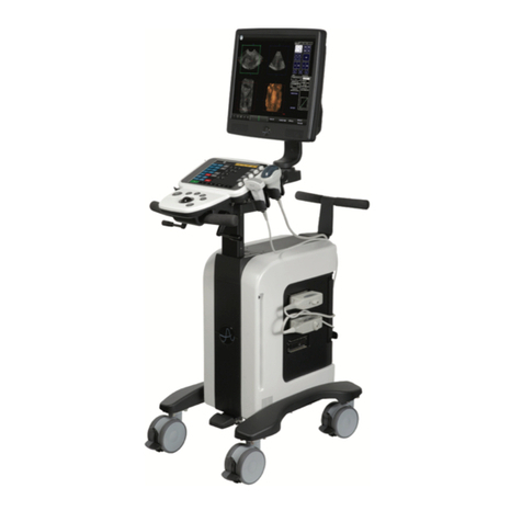
Ultrasonix
Ultrasonix SonixTouch Q+ Service manual
