Operation
&
Service
Manual
MODEL
6325
Table
of
Contents
M
GENERAL
OPERATING
INSTRUCTIONS
e
Pre-Operation
Check
.......................................
1
*
Use
of
Bed
Hook............................................
1
+
Operation
....................................,..,.,,,,,4.
1
e
Cycle
Monitor
..........................,,..................
1
©
Comfort
Cooling
...................................,........
1
+
Power
Cord
Storage
........................................
1
+
Sleeve
Compatibility
........................................
1
M
FAULT
CONDITIONS
e
Fault
Messages
.................................,..,..,..
24
ㆍ
Watchdog
Circuit
.........................................1
4
M
CONTRAINDICATIONS
...........................,.............
5
M
CAUTIONS
.............................,.,....,..........,.,.
5
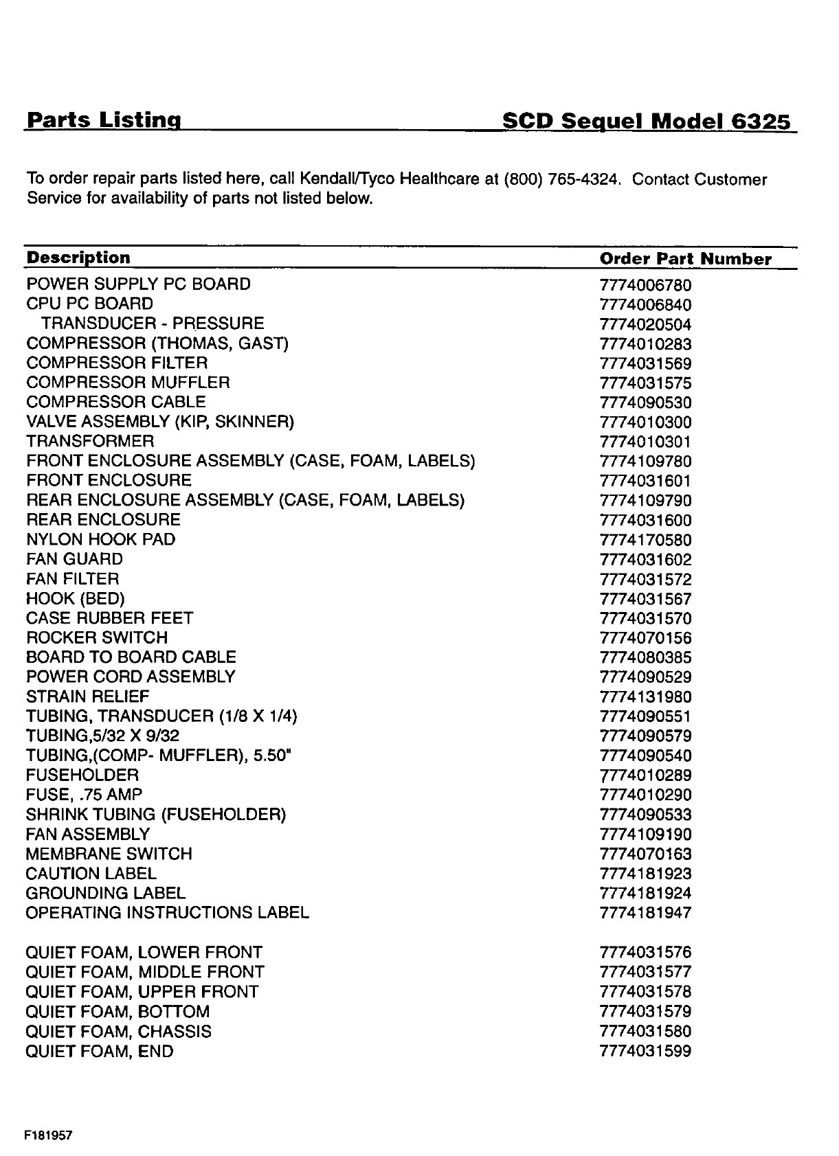
E
SERVICE
AND
MAINTENANCE
slntroduction.............................
eee
6
e
Warranty
and
Factory
Service
...............................
6
+
Maintenance
.........................................,....
6-7
e
Ventilation
.................................................
7
efFuses.................................
eee
7
+
Electrical
Safety
............................................
7
e
Cleaning
.................................,...............
7
*
Electrical/Electronics
Description
...........................
7
e
Pneumatic
Description
...............................:
Fer
8
e
Portidentity
............................................
8
»
System
Start-Up
Routine
....................................
8
+
Pressure
Monitoring
........................................
8
(Continued
on
next
page}