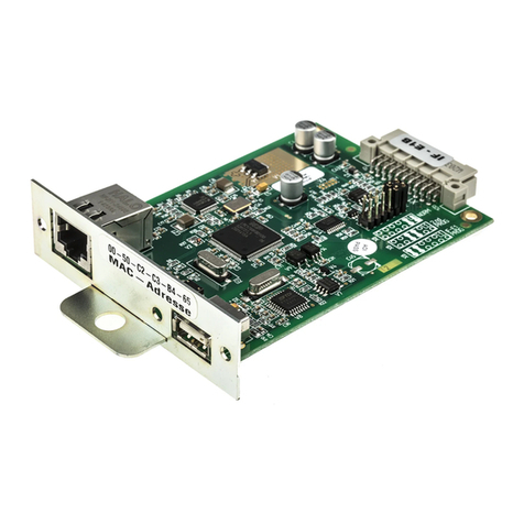
Elektro-Automatik IF-U1 User manual

User Manual
Interface Cards
USB / RS232 / GPIB /
CAN / Analog / Ethernet /
Profibus
IF-U1 (USB): 33 100 212 IF-U2 (USB): 33 100 220
IF-R1 (RS232): 33 100 213 IF-R2 (RS232): 33 100 221
IF-C1 (CAN): 33 100 214 IF-C2 (CAN): 33 100 222
IF-A1 (ANA): 33 100 215 IF-E1B (Ethernet): 33 100 227
IF-G1 (GPIB): 33 100 216 IF-E2B (Ethernet): 33 100 228
IF-PB1 (Profibus): 33 100 219

2
User Manual
Interface cards IF-XX
EN
Date: 22-10-2015
Important!
• Only equip the interface card(s) in units which are de-
signed to be used with them! It is not required to open
the unit. Information about which devices are capable of
running these interface cards can be requested from your
local dealer or read in the user manual of the devices.
• Only equip the interface card(s) while the unit is switched
off by the mains switch!
• Units featuring two slots might be equipped with two
cards, but you can’t combine them arbitrarily. For detailed
information see section „3.3 Combining interface cards“
• Never remove the covers from the cards!
• If only one card is equipped in units with two slots it is
recommended to install the default slot cover to the open
slot. This protects the unit from additional dust pollution
and ensures correct air circulation with the internal fans.
• Use and follow the common ESD provisions when install-
ing and removing the interface cards!
About & Copyright
Elektro-Automatik GmbH & Co. KG
Helmholtzstrasse 31-33
41747 Viersen
Germany
Phone: +49 2162 / 37850
Fax: +49 2162 / 16230
Web: www.elektroautomatik.de
Mail: [email protected]
© Elektro-Automatik
Reprint, duplication or partly, wrong use of this user manual
are prohibited and might be followed by legal consequences.

3
User Manual
Interface cards IF-XX
EN
Date: 22-10-2015
Page
1. General........................................................................................................................................................................... 5
1.1 Area of use................................................................................................................................................................ 5
1.2 The concept .............................................................................................................................................................. 5
1.3 Warranty & repair ...................................................................................................................................................... 5
1.4 Used symbols............................................................................................................................................................ 5
1.5 Scope of delivery....................................................................................................................................................... 5
2. Technicalspecications.................................................................................................................................................. 6
3. Installation ...................................................................................................................................................................... 7
3.1 After unpacking ......................................................................................................................................................... 7
3.2 Inserting a card ......................................................................................................................................................... 7
3.3 Combining interface cards ........................................................................................................................................ 7
4. RS232 card IF-R1 / IF-R2 .............................................................................................................................................. 8
4.1 Configuring the RS232 card...................................................................................................................................... 8
5. USB card IF-U1 / IF-U2.................................................................................................................................................. 8
5.1 Configuring the USB card ......................................................................................................................................... 8
6. CAN card IF-C1 / IF-C2.................................................................................................................................................. 9
6.1 Configuring the CAN card ......................................................................................................................................... 9
6.2 CAN IDs .................................................................................................................................................................. 10
6.2.1 Old CAN ID system .......................................................................................................................................... 10
6.2.2 New CAN ID system since June 2011 ............................................................................................................. 10
7. Analogue interface IF-A1...............................................................................................................................................11
7.1 Pin assignment of the analogue interface (25-pole D-Sub socket) ..........................................................................11
7.2 General ................................................................................................................................................................... 12
7.3 Configuring the IF-A1 .............................................................................................................................................. 12
7.3.1 Analogue inputs ............................................................................................................................................... 12
7.3.1.1 PSI 9000 series......................................................................................................................................... 12
7.3.1.2 PSI 8000 series......................................................................................................................................... 13
7.3.2 Analogue outputs ............................................................................................................................................. 13
7.3.3 Digital inputs..................................................................................................................................................... 14
7.3.4 Digital outputs with determined functionality.................................................................................................... 15
7.3.5 Digital outputs with user-definable functionality ............................................................................................... 16
8. GPIB card IF-G1........................................................................................................................................................... 17
8.1 Controlling a device via GPIB ................................................................................................................................. 17
8.2 Terms explained ...................................................................................................................................................... 17
8.3 Firmware updates ................................................................................................................................................... 17
8.4 Transmission and execution times.......................................................................................................................... 17
8.5 Configuring the IF-G1.............................................................................................................................................. 17
9. Ethernet cards IF-E1B and IF-E2B............................................................................................................................... 18
9.1 Preparation / Notes about operation ....................................................................................................................... 18
9.2 Configuring the Ethernet card ................................................................................................................................. 18
9.2.1 On the device................................................................................................................................................... 18
9.2.2 With the IP-Config tool ..................................................................................................................................... 19
9.2.3 On the device website...................................................................................................................................... 19
9.3 Communicating with the device .............................................................................................................................. 20
9.3.1 Communication via HTTP ................................................................................................................................ 20
9.3.2 Communication in LabView.............................................................................................................................. 20
9.3.3 Communication in other programming languages ........................................................................................... 20
9.3.4 Communication via the USB port..................................................................................................................... 20
9.4 Firmware updates ................................................................................................................................................... 21
9.5 Trouble-shooting ..................................................................................................................................................... 21
10.ProbuscardIF-PB1.................................................................................................................................................... 22
10.1 Transmission speed ................................................................................................................................................ 22
10.2 Configuring the Profibus card.................................................................................................................................. 22
10.3 Connecting the bus ................................................................................................................................................. 22
10.4 Bus termination ....................................................................................................................................................... 22
Table of contents

4
User Manual
Interface cards IF-XX
EN
Date: 22-10-2015
Table of contents
10.5 Implementation on the control side ......................................................................................................................... 22
10.6 Other features ......................................................................................................................................................... 22
10.7 Updating the firmware ............................................................................................................................................. 23
10.8 Communication via the USB port ............................................................................................................................ 23
11. Notes about particular device series ............................................................................................................................ 24
11.1 Series EL 3000 / EL 9000 ....................................................................................................................................... 24
11.2 Series PS 8000 T/ DT / 2U / 3U .............................................................................................................................. 24
11.3 Series PSI 800 R and BCI 800 R ............................................................................................................................ 24
12. The System Link Mode (PSI9000 only)........................................................................................................................ 25
12.1 Handling the System Link Mode ............................................................................................................................. 25
12.1.1 Display and handling of the master.................................................................................................................. 25
12.1.2 Display at the slaves ........................................................................................................................................ 25
12.1.3 Special alarms, warnings and signals.............................................................................................................. 26
12.2 Configuration of the System Link Mode .................................................................................................................. 26
13. Programming................................................................................................................................................................ 27
14. Connectors................................................................................................................................................................... 28

5
User Manual
Interface cards IF-XX
EN
Date: 22-10-2015
About the interface cards
1. General
The interface cards IF-Rx (RS232), IF-Cx (CAN), IF-Ux
(USB), IF-G1 (GPIB), IF-Ex (Ethernet) and IF-PB1 (Profibus)
provide a digital and the IF-A1 an analogue connection to
a control unit like a PC or PLC. Devices like, for example,
a power supply can be monitored and controlled. Basic
software for power supplies and electronic loads, for the
use with some of these interface cards, is supplied with the
included tools CD.
The models IF-U2, IF-R2, IF-C2 and IF-E2B are reduced ver-
sions of the -1 types and may only be used in certain series.
The 25 pole, analogue interface card IF-A1 (supported by
series PSI 9000 and PSI 8000) allows fast monitoring of
actual values and fast setting (with a very short delay) of
set values, all within the nominal values of the device. The
digital inputs and outputs can be parametrised.
PSI 9000 series only: with the combination of a RS232 or
USB card and a CAN card, the user can realise a gateway
from the RS232 or USB port of a PC to a CAN bus. Thus no
extra hardware is required to connect the PC to CAN. The
gateway allows to control up to 30 units in line by the RS232/
USB and CAN cards. The device that is connected to the
PC will handle the data conversion to CAN and back. The
maximum data transmission speed is then limited to what
the serial connection has been set to. Total maximum baud
rate is 57600 baud.
PSI 9000 series only: the cards IF-R1 and IF-U1 addition-
ally support the parallel and/or series connection of multiple
laboratory power supplies to a true master-slave system with
totals formation of the measured values by using the „System
Link mode“. Also see user guide of PSI 9000 and section
„12. The System Link Mode (PSI9000 only)“.
1.1 Area of use
The interface cards must only be equipped in units which
are designed for them.
A set of Labview VIs is included in the package, which will
simplify the use and implementation of the interface cards
in the LabView IDE.
The implementation in other applications and environments
is possible, but also very complex. The telegram structure is
explained in detail in separate documents, available on the
included CD in folder „\manuals\interface cards\“ or on our
web site (ZIP file with instruction manuals for all interface
cards).
The voltage range of the analogue input and output signals
of the IF-A1 is customisable between 0 and 10V. The digital
inputs can be switched between two different voltage ranges
for the logical level and the default logical level can be pre-
defined for the case that these inputs are not used.
1.2 The concept
The interface cards are pluggable and can thus be used
where needed. They are compatible to various types of de-
vices, such as electronic loads. Due to the electrical isolation
of 2000V (with Profibus card: 1000V) you can also connect
multiple devices with different potentials.
The USB, RS232 and CAN interfaces support a unique
communication protocol, which is object orientated. Every
series has its dedicated object (ie. command) list, which
differs depending on the features of a model. Transmitted
commands are checked for validity and plausibility. Non-plau-
sible or erroneous values and objects result in an error which
is sent as an answer telegram.
The digital cards IF-G1 and IF-Ex use the standardised
command language SCPI (Standard Commands for Pro-
grammable Instruments).
Interface IF-PB1 follows the Profibus specification.
Refer to section „13. Programming“ for an overview about
further available documentation.
1.3 Warranty & repair
Attention: The interface card must not be repaired by the
user!
In case of warranty or a defect please contact your supplier
to get informed about the next steps. The cards are conceded
with a statutory warranty of two years (for Germany), which
is independent from the warranty (and its duration) of the
device they are used in.
1.4 Used symbols
In the following description the display and operating ele-
ments are marked differently by symbols.
= Displayed only, all elements which are only dis-
played and which represent a state are marked with this
symbol
= Parameter, changeable values, are marked with
this symbol and are emphasised
= Menu items, selectable, lead to the next sub-level or
to the bottom level with parameters
Brackets {…} mark possible options or adjustment ranges
for parameters.
1.5 Scope of delivery
1 x Pluggable interface card
1 x CD with software, instruction manuals and more
1 x Short installation guide
1 x Patch cable, 0.5m (only with IF-R1 and IF-U1)
1 x USB cable A-A, 1.8m (only with IF-Ux, IF-Ex, IF-PB1 )
1 x RS232 cable, 1:1, 3m (only with IF-Rx)
1 x Adapter cable for firmware updates (only with IF-G1)

6
User Manual
Interface cards IF-XX
EN
Date: 22-10-2015
2. Technical specications
General
Dimensions Type 1 (W x H x L) 24 x 80 x 100mm
Dimensions Type 2 (W x H x L) 24 x 80 x 45mm
Safety EN 60950
EMI Standards EN61000-6-4,
EN 61000-6-2,
EN 55022 Class B
Overvoltage category Class II
Operation temperature 0...40°C
Storage temperature -20...70°C
Relative humidity <80% (w/o condensation)
IF-R1 / IF-R2 (RS232)
Electrical isolation 2000V DC
Connectors 1 x 9-pole D-Sub socket (f.)
2 x RJ45 socket (not IF-R2)
Baud rates 9600Bd, 19200Bd,
38400Bd, 57600Bd
Cable length depending on the baud rate,
up to 15m
System Link Mode yes (only with IF-R1)
(IF-R1 and PSI 9000 only)
└Max.numberofunits 30
└Bustermination settableintheunit’smenu
└Patchcable 0.5m,included
IF-U1 / IF-U2 (USB)
Electrical isolation 2000V DC
Connectors 1 x USB socket type A
2x RJ45 socket (not IF-U2)
Standard USB 1.1
Cable length max. 5m
System Link Mode yes
(IF-U1 and PSI 9000 series only)
└Max.numberofunits 30
└Bustermination settableintheunit’smenu
└Patchcable 0.5m,included
IF- C1 / IF-C2 (CAN)
Electrical isolation 2000V DC
Connectors 9-pole D-Sub socket (f.)
9- pole D-Sub socket (m.)
Baud rates 20kBd...1MBd in steps
Bus termination settable in the unit’s menu
CAN standard V2.0 part A
About the interface cards
IF-A1 (Analogue)
Electrical isolation 2000V DC
Analogue inputs:
Input voltage range
Maximum range -5V...+15V
Nominal range 0V…10V
Inputimpedance 25kΩ
Resolution
VSEL, CSEL, PSEL (RSEL) < 2mV
Relative error
VSEL, CSEL, PSEL 0.1%
RSEL (Option) 0.25%
Response time1) < 4ms
Analogue outputs:
Nominal output voltage range
VMON, CMON, PMON 0V…10V
Iout max. at 10V 2mA
VREF 1V...10V
Iout max. at 10V 10mA
Resolution
VMON, CMON, PMON, VREF < 2mV
Relative error
VMON, CMON, PMON, VREF 0.1%
Settling time of the analogue outputs < 4ms
Auxiliary voltage 12…15V
Current max. 50mA
Digital outputs:
Type pull-up resistor to +15V
Output current
Maximal Imax = -20mA
at Uout = 0.5V
Nominal 1...10mA
Output voltage
High +15V
Low < 0.3V
Response time2) < 4ms
Digital outputs:
Input voltage
Maximum range -5V...+30V
if set to: Level=LOW
ULow < 1V
UHigh > 4V
if set to: Level=HIGH
ULow < 5V
UHigh > 9V
Input current
if set to Low Range and Default Level = L
Uin= 0V 0mA
Uin= 12V +2.6mA
Uin= 24V +5mA
if set to Low Range and Default Level = H
Uin= 0V -1.5mA
Uin= 12V +2.2mA
Uin= 24V +6mA
1 In order to calculate the total response time of a step change, from an analogue
interface input to the power output you need to add the response time of the device
to this time.
2 Timebetweenoccurrenceoftheeventwhichisgoingtobenotiedandthemo-
mentthenoticationisexecuted.

7
User Manual
Interface cards IF-XX
EN
Date: 22-10-2015
About the interface cards
if set to High Range and Default Level = L
Uin= 0V 0mA
Uin= 12V +1.6mA
Uin= 24V +3.5mA
if set to High Range and Default Level = H
Uin= 0V -1.5mA
Uin= 12V +0.7mA
Uin= 24V +4.5mA
Response time1) < 10ms
IF- G1 (GPIB)
Electrical isolation 2000V DC
Terminals 24pole Centronics socket (female)
Bus standard IEEE 488.1/2
Cable length (GPIB) 2m per device, 20m total
Cable type (GPIB) Standard GPIB cable
IF-E1 / IF-E1B (Ethernet)
Electrical isolation 1500V DC
Terminals 1x RJ45 (LAN / WAN)
1x USB, type A
Cable type (Ethernet) Twisted pair, patch cable,
Cat 3 or higher
Protocols HTTP, TCP/IP
Network ports 0 - 65535 (80=HTTP)
Default: 1001 (TCP/IP)
Network connection 10/100 MBit
USB connection USB 1.1, 2.0
Transmission speed Ethernet 100 kBaud
Transmission speed USB 57600 Baud
Command interval max. every 10ms
Keep-alive time-out 10min.
IF-PB1 (Probus)
Electrical isolation 1000V DC
Terminals 1x Sub-D 9pole
1x USB, type A
Variant DP
Bustermination viaProbuscable
Bus speed up to 12MBit/s
Protocols DPV0, DPV1
Identication withGSD/GSEle
1 Time between the occurrence of an event, that has to be signalised to an
output, and the moment it is signalised.
3. Installation
3.1 After unpacking
After unpacking, check the pluggable interface card(s) for
signs of physical damage. If any damage can be found do
not use and insert the card into any device!
3.2 Inserting a card
The card(s) must only be inserted while the unit is completely
switched off. The unit does not have to be opened. Remove
the screws from the slot cover or from an already equipped
card and remove the cover/card. Insert the new card with
caution until the card plate touches the rear side of the unit.
If there is space between the rear side and the card
plate, do not tighten the screws, because the card is not
placed correctly! The wiring between the PC and/or other
units has also be done before the unit is switched on again.
The card(s) will be automatically detected by the device after
powering it on and can now be configured.
Note about the IF-A1: before equipping the card, you should
set the jumpers correctly. Refer to „7.3 Configuring the IF-
A1“, subsection „Digital inputs“.
Note: in case the card was purchased subsequently and is
not recognized by the device, it might be necessary to update
the firmware of the device. Please contact your dealer for
further information.
Caution! There are components on the card which are sen-
sitive for ESD. You must follow the general ESD provisions
when handling and installing a card.
3.3 Combining interface cards
Only applies for series PSI 9000!
In case more than one card slot is used, the table shows
which cards can be combined (• means allowed):
IF-U1 IF-C1 IF-R1 IF-E1 /
IF-E1B IF-G1 IF-A1 IF-PB1
IF-U1 - • - - • - -
IF-C1 • - • - - • •
IF-R1 - • - - • - -
IF-E1 /
IF-E1B - - - - - - -
IF-G1 • - • - - • •
IF-A1 - • - - • - -
IF-PB1 - • - - • - -

8
User Manual
Interface cards IF-XX
EN
Date: 22-10-2015
4. RS232 card IF-R1 / IF-R2
The RS232 interface card links the power supply with a
controlling unit (PC) via its serial port, also called COM
port. In case the PC does not feature one of these older
serial ports anymore, there are adapter cables available in
selected stores, which work via USB and generate a virtual
COM port on the PC.
The settings of this serial connection have to be configured
on both ends to the same values. At the power supply this is
done in the setup menu. A 1:1 cable has to be used.
The card type 1 (IF-R1) features an additional serial interface
which is used to link multiple power supplies in order to build
the System Link Mode. More information can be found in
section „12. The System Link Mode (PSI9000 only)“.
Attention!
The RJ45 sockets of the IF-R1 card ARE NO Ethernet
ports. Do NOT connect to a network!
4.1 Configuring the RS232 card
The interface card is configured in the setup menu.
It not required to set the device address (node) here, since
RS232 is point-to-point. To simplify communication, the so-
called broadcast address 0 can be used to access the device
disregarding its particular address.
Activate the menu with
M
+ Communication +
Slot: { IF-… } depends on the equipped card
Only with PSI 9000 there is another slot available:
Slot A: { IF-… } depends on the equipped card
Slot B: { IF-… } depends on the equipped card
Here you set the desired device node and you also get an
overview which card(s) is/are currently installed. By selecting
the card with, for example,
Slot: IF-R1 +
you enter the configuration card‘s menu. If two are equipped
(PSI 9000), each card has to be configured individually. You
can now setup the parameters:
device node Default: 1
= {1..30} Choose one of up to 30 device nodes
Baud rate Default: 57.6 kBd
= {9.6 kBd, 19.2 kBd, 38.4 kBd, 57.6 kBd}
The selected baud rate has to be determined in dependency
of the used cable length. At 15m a maximum of 9.6 kBd is
strongly recommended. 1kBd = 1000Bd.
5. USB card IF-U1 / IF-U2
The USB interface works similar to the RS232 card, but it is
more comfortable when connecting multiple units to a PC,
because nowadays PC feature multiple USB ports. Alterna-
tively, devices with this USB card could be connected via a
USB hub.
The card IF-U1 features an additional RS485 interface which
is used to link multiple power supplies of series PSI 9000 in
order to build the System Link Mode. More information can
be found it in section „12. The System Link Mode (PSI9000
only)“.
Attention!
Never connect any of the RJ45 sockets of the IF-U1
card to an Ethernet hub or switch or Ethernet port of
a PC!
5.1 Configuring the USB card
The interface card is configured in the setup menu.
It not required to set the device address (node) here, since
USB is point-to-point. To simplify communication, the so-
called broadcast address 0 can be used to access the device
disregarding its particular address.
Activation of the menu is the same as with the RS232 card
in section 4.1.
Here you set the desired device node and you also get an
overview which cards are currently installed. A further con-
figuration of the USB card is not required.
Note
The USB driver installs a virtual COM port (VCP) on the
PC. This COM port has to be congured with certain pa-
rameters if used to communication with the device (see
„13. Programming“).
About the interface cards

9
User Manual
Interface cards IF-XX
EN
Date: 22-10-2015
About the interface cards
6. CAN card IF-C1 / IF-C2
CAN Standard: V2.0 part A
Cable length: depending on the baud rate
The communication over the CAN bus is specifically de-
signed to suit the needs of test applications and systems,
like for instance in the automotive industry. A subsequent
implementation into existing systems and the modification of
a related software application is possible and unproblematic.
The networking of CAN devices provides the advantage of a
faster communication and a fail-safe bus topology. The driver
chip on the CAN card can support up to 110 device nodes
(the term „device node“ is used for CAN bus members).
The communication protocol can handle up to 30 units per
address segment (RID). Thus it is theoretically possible to
set up a bus system of up to 110 units, which will operate
with at least 4 address segments. The address segments
are relocatable, so that the one or multiple devices can be
implemented into an existing CAN bus without the need to
reconfigure the whole system.
6.1 Configuring the CAN card
The interface card is configured in the setup menu.
By selecting the card with
Slot: IF-C1 +
you enter the configuration menu for that particular card.
Each card has to be configured individually. You can now
setup some parameters.
Figure shows IF-C1 settings of CAN-ID system “normal”, for
“Vector” see section 6.2.2.
Setting the baud rate
All common baud rates between 10kBd and 1MBd are sup-
ported. Only with PSI 9000 (old series until 2012) models,
for each baud rate setting the so-called „Sample point“ can
be chosen, which is used to optimise the data transmission
for various cable lengths and qualities. It adjusts the point
of time when a transmitted bit is sampled.
baudrate Default: 100 kBd
sample point: 75% (only available with series PSI 9000)
= { 10 kBd { 60, 65, 70, 75, 80, 85}%,
20 kBd { 60, 65, 70, 75, 80, 85} %,
50 kBd { 60, 65, 70, 75, 80, 85} %,
100 kBd { 60, 65, 70, 75, 80, 85} %,
125 kBd { 58, 68, 70, 75, 81, 87} %,
250 kBd { 58, 68, 70, 75, 81, 87} %,
500 kBd { 58, 66, 75, 83} %,
1 MBd { 58, 66, 75, 83} % }
Bus termination
The CAN bus requires a termination resistor of 120 Ohms
on both ends of the line. If a unit is located at the end of the
chain/line and it is not connected to a next unit, it has to be
terminated. The parameter „bus terminate“ is used to easily
set the termination without any circumstantial hardware
termination by jumpers.
bus terminate Default: NO
=YES The bus is terminated with a 120Ω resistor.
=NO No termination is done.
Gateway function (only PSI9000)
CAN Default: Client
=Client The device is monitored and controlled by an
external unit, like a PC or a SPS
=Gateway The interface card additionally serves as a
gateway between the CAN and RS232/USB
cards
The RS232 or USB card inside a device with gateway fea-
ture (only available with old PSI 9000 series until 2012) and
which is assigned as gateway allows the user to control and
monitor all further units, which are linked to that particular
device by CAN. All that is needed is a device with an extra
IF-R1 or IF-U1 interface card to set up a CAN bus system.
Both cards, RS232 and USB, can only utilise the high per-
formance of the CAN bus very poorly. In order to use the
CAN bus with full performance (high data rate) and many
devices, it is recommended to directly control the bus with
a CAN master hardware.

10
User Manual
Interface cards IF-XX
EN
Date: 22-10-2015
6.2 CAN IDs
6.2.1 Old CAN ID system
It is absolutely necessary to choose and set a unique device
address, also called „device node“, for every connected or
linked unit. Only then a unit can be identified and controlled
correctly. These identifiers are used to access a unit.
Relocating address segments
In case that devices are retrofitted with a CAN card and
implemented into an existing CAN bus system, the „relo-
catable identifier segment“ (short: RID) is used to relocate
the address segment in order to adapt the addresses of the
new unit(s) to the address range of the already existing units
or to set it away from that range to not collide.
The CAN bus after the standard V2.0a defines an 11 bits long
address (=identifier). This results in a total of 2048 identifiers,
while from 2032 can be chosen. Those 2048 identifiers are
separated into 32 address segments of 64 addresses. The
starting address is determined by the RID.
relocatable ID Default: 0
segment = { 0..31} Select (relocate) the address range
Inside of every address segment are 62 freely assignable
addresses, whereas the up to 30 units are using the lower
range and with 2 physical addresses (identifiers, one each
for sending and querying data) per unit they are taking the
addresses from 2...61. The addresses 0 and 1 of every
address range are reserved for broadcast messages. This
results in 32*2 broadcast addresses.
For broadcast messages the addresses are static:
[RID*64 + 0] and [RID*64 + 1].
Example: the RID is set to 5 (also see setup menu of your
device). A broadcast shall be sent to all units of this address
range. The identifier hence calculates as 5*64 = 320 = 0x140,
or 0x141 for queries.
For single cast messages every „device node“ is occupy-
ing another two addresses:
[RID*64 + device node * 2] and
[RID*64 + device node * 2 + 1]
Example: the RID was set to 13, the device address (node)
to 12. In order to control the device, the identifier has to be:
13*64 + 12*2 = 856 (0x358). The identifier 857 (0x359) is used
for queries.
About the interface cards
6.2.2 New CAN ID system since June 2011
The new CAN ID system is first available for PS 8000 and
EL3000/EL9000 series, other series like PSI 8000 follow. Further
series upon request.
For this system, it is required to set a base CAN ID. This will
determine the three CAN IDs which are used by the device.
The other ID, the broadcast ID, can be ignored if unused and
not colliding with the standard IDs.
For the settings for a PS 8000 power supply model please refer
to the instruction manual of the device.
For a PSI 8000 model, the CAN setup will look like this:
Base ID Default: 0x000
The base ID is adjusted as hexadecimal value in steps of
4. The device will then use three normal CAN IDs: base ID,
base ID + 1 and base ID + 2.
This system is compatible to Vector software like CANoe or
CANalyzer. Databases in *.dbc format are available either
directly on the CD that comes with the interface card or
upon request. For every device model, a unique database is
required. Demo configurations for testing purposes that can
be loaded into CANoe or CANalyzer will also be available.
Broadcast ID Default: 0x7FF
This adjusts the so-called broadcast ID as hexadecimal
value. This ID must not collide with one of the other IDs of
the unit.
The purpose of the broadcast ID is to adjust it to the same
value on several units on the same bus in order to send
command to all units at once. This might be required when
setting a current or the output condition simultaneously on
these units.
This ID can only be used to send set values or condition, not
to query status or similar.
The other settings are like described in section 6.2.1.

11
User Manual
Interface cards IF-XX
EN
Date: 22-10-2015
About the interface cards
7. Analogue interface IF-A1
7.1 Pin assignment of the analogue interface (25-pole D-Sub socket)
Pin Name Function Description Default level5) Electricalspecications
1 AI1 PSEL /
RSEL 6)
Analogue input: Set value power /
Analogue input: Set value resistance 6)
0..10V correspond to 0..100% Pnom /
0..10V correspond to 0..100% Rmax
Accuracy @0...10V typ. < 0.1% 1)
Input impedance Ri> 25k
2 AI3 CSEL Analogue input:
Set value current 0..10V correspond to 0..100% Inom
3 AI2 VSEL Analogue input:
Set value voltage 0..10V correspond to 0..100% Unom
4 AO3 PMON Analogue output:
Actual value power 0..10V correspond to 0..100% Pnom
Accuracy typ < 0.1%1) at Imax = +2mA 4)
Short-circuit-proof against GND
5 AO1 VMON Analogue output:
Actual value voltage 0..10V correspond to 0..100% Unom
6 AO2 CMON Analogue output:
Actual value current 0..10V correspond to 0..100% Inom
7 DO1 CV Digital output:
Constant voltage operation
CV active = Low
CV not active= High
Quasi open collector with pull-up resistor
against VCC
Imax = -10mA 4) at Ulow= 0.3V
Umax= 0...30V
Short-circuit-proof against GND
Receiver: Ulow < 1V; Uhigh > 4V)
8 DO2 OVP Digital output:
Overvoltage protection active
OVP = High
No OVP = Low
9 DO3 OT Digital output:
Overtemperature error
OT = HIGH
No OT = Low
10 DO4 Mains Digital output:
Mains voltage OK
Mains OK = Low
Mains not OK = High
11 DO5 Standby Digital output:
Output off
Output off = Low
Output on = High
12 DO6 CC Digital output:
Constant current operation „CC“
CC active = Low
CC not active= High
13 DO7 CP Digital output:
Constant power operation „CP“
CP active = Low
CP not active = High
14 AGND SEL 2) Reference potential for the
analogue inputs Reference for SEL signals
15 AGND2) Reference potential for the
analogue outputs Reference for MON signals and VREF
16
17 N.C.
18 AO0 VREF Analogue output:
Reference voltage 10V Accuracy typ < 0.1% 1), Imax = + 8mA 4)
Short-circuit-proof against GND
19 +VCC Auxiliary voltage
(Reference: DGND) 12V…16V Imax = +50mA4)
Short-circuit-proof against DGND
20 DGND 2) Reference potential of the digital
ports
Reference for +VCC, control and
noticationsignals
21
22 DI1 SEL-enable
Digital input:
Switch-over to external interface
(else: local operation)
„Default Level“ set to „H(igh)“ by
jumpers. Standard activation:
SEL-enable on = Low
SEL-enable off = High
Preselectable input level (High/Low range):
3)
1) ULow = < 1V ; UHigh = > 4V or
2) ULow = < 5V ; UHigh = > 9V
Preselectable logic level if input is not
wired:
open = High Level or Low Level
23 DI2 Rem-SB Digital input:
Output off
„Default Level“ set to „H(igh)“ by
jumpers. Standard activation:
REM-SB on = Low
REM-SB off = High
24 Reserved
25 N.C.
1) The input range is adjustable. When using a range other than 0...10V, the accuracy will decrease proportionally. For example, for a range of 0...5V for 0...100%, the accuracy will be only <0.2% etc.
2)AGNDandDGNDareconnectedinternally.AGNDSELatPin14isindependent.Itservesasreferenceforthedifferenceampliersofallanalogueinputs.
DIx, DOx, +Vcc are referenced to DGND. VREF, VMON, CMON, PMON are referenced to AGND. VSEL, CSEL und PSEL are referenced to AGND SEL.
3) Digital input, depending on the preset with the jumpers:
a) Setting High Range (high threshold): Uin = 0V; I = -1.5mA, Uin = 12V; I = +0.7mA; Uin = 24V; I = +4.5mA, Thresholds: ULow = < 5V; UHigh = > 9V
b) Setting Low Range (low threshold): Uin= 0V; I = -1.5mA, Uin = 12V; I = 2.2mA, Uin = 24V; I = +6mA, Thresholds: ULow = < 1V; UHigh = > 4V
4)Positivecurrentsareowingoutofthedevice,negativecurrentsareowingintoit.
5) With certain device series, the standard level may/can be changed by the user in the device setup menu
6)RSEL(internalresistancesetvalue)isonlyremotelycontrollablewithpowersuppliesofseriesPSI9000(oldseriesuntil2012)-->it’sgenerallyrequiredtounlocktheoption„Internalresistance“rst

12
User Manual
Interface cards IF-XX
EN
Date: 22-10-2015
About the interface cards
7.2 General
The interface IF-A1 is an analogue interface with galvani-
cally isolated, customisable, analogue and digital inputs and
outputs. Visualisation:
IF-A1
Netzgeräteseite
PSU side
Ein/Ausgänge
In/Out
Customisable means, that you can customise these inputs
and outputs to your needs, but always within a voltage
range of 0...10V. At devices with two extension card slots
(eg. PSI9000) it is possible to combine the IF-A1 with a
digital interface card (eg. IF-U1 (USB)), in order to control,
for example, the device by USB and put out actual values
via the analogue outputs of the analogue card. Or vice versa,
you control the device by analogue set values and read out
and log the actual values to a PC via RS232, CAN or USB.
It applies generally: all monitoring and surveillance features
are permanently active, even if two cards (one digital, one
analogue) are equipped. Only the control of the device with
set values requires the activation of the external mode (IF-A1)
resp. of the remote mode (digital interfaces), whereas the
remote mode has priority. In case the device is in control
by an analogue interface (external mode, indicated in the
display by extern) and the control of the device via a digital
interface is activated, the device will switch to remote mode
(indicated in the display by remote).
7.3 Configuring the IF-A1
The interface is configured in the communication menu:
With
M
+ Communication + and
Slot {A|B}: IF-A1 +
the analogue interface card is selected for configuration.
Following parameters can be set:
7.3.1 Analogue inputs
Analogue set values are only accepted by the device if it is in
external mode (indicated in the display by extern). Access
to the menu is blocked in external mode.
The analogue interface IF-A1 has three analogue inputs
with these functions:
AI1: PSEL (external set value for power)
AI3: CSEL (external set value for current)
AI2: VSEL (external set value for voltage)
The nominal voltage range of these inputs is 0...10V, but
it can be narrowed in order to adapt to the input signal. By
limiting the standard voltage range to a lower one the reso-
lution is also lowered. Example: if the voltage range is set to
only 1V difference, resolution and accuracy will be reduced
by the factor 10.
The left value defines the input voltage for 0% output value
(U, I, P), the right value the input voltage for 100% output
value. The menu differs a little between the various series:
7.3.1.1 PSI 9000 series
It applies:
Umin (left value) = { 0.00V...4.00V }
Umax (right value) = { 5.00V...10.00V }
Ahigherorlowervoltagethanspeciedisclippedandtreat-
ed as either 0% or 100%.
Menu items:
{Nom.value | Adj.limits} Default: Nom.value
= Nom.value the dened range for VSEL, CSEL and
PSEL is always related to the nominal
values of the device (see explanations
below)
= Adj.limits the range for VSEL, CSEL and PSEL
is always related to the adjustment
limits of the device (see explanations
below)

13
User Manual
Interface cards IF-XX
EN
Date: 22-10-2015
AI1 Default: PSEL 0.00 10.00V
= {PSEL|RSEL|-} Pin assigned to external set value for
power or resistance or not used
RSEL is only available if U/I/R mode is unlocked.
If AI1 is set to „-“, then no power set value is required. The
output power will then be held at the last adjusted value.
AI2 Default: 0.00 10.00V
= VSEL external set value for voltage
AI3 Default: 0.00 10.00V
= CSEL external set value for current
Explanation about Nom.value
With this setting, the input voltage range of the three set
values inputs is related to the corresponding nominal values
(U, I or P) of the device.
Example: you have a PSI 9080-100 which has nominal
values of 80V, 100A and 3000W. If you adjust the analogue
input VSEL to 0...10V for 0...100%, the device will put out
100% or 80V if the input is fed a voltage of 10V. In case the
range is set to 3...7V, the 100% or 80V output voltage is
already achieved when feeding 7V input. The same applies
for the other set value inputs.
Note
The maximum output voltage, current and power can
additionally be limited by adjustment limits. See the user
instruction manual of your device, menu item „Prole ->
General settings -> Adjust limits“ for further details.
Explanation about Adj.limits
With this setting, the input voltage range of the three set
values inputs is related to the so-called „adjust limits“ (U, I
or P) which can be defined in the user profile of the device.
Example: you have a PSI 9080-100 which has nominal val-
ues of 80V, 100A and 3000W. The output current is set to
50A in the „Adjust limits“ menu of the device profile in order
to prevent the device from ever putting out more than 50
amps. If you then adjust all three analogue inputs to 0...5V
for 0...100%, the device will put out 100% or 80V output
voltage at 8V input on VSEL, 100% or 3000W power at 8V
input on PSEL, but only 50A when you supply 8V on CSEL
input. At 4V on CSEL it will put out max. 25A.
7.3.1.2 PSI 8000 series
Note
PSI 8000 series models of type T, DT, 2U or 3U feature a
built-in analogue interface. In the menu there is an item
„Analogue interface“, which is NOT related to the pluggable
interface card IF-A1 that is described here!
It applies:
Umin (left value) = { 0.00V...4.00V }
Umax (right value) = { 5.00V...10.00V }
About the interface cards
The adjusted voltage range, for example 2.00V...8.00V,
corresponds to 0...100% set value. A higher or lower volt-
age is clipped and treated as either 0% or 100%. Also see
„Explanation about Nom.value“ above, because PSI 8000
series incorporate the behaviour described in that section.
Menu items:
AI1 Default: PSEL 0.00 10.00V
= PSEL external set value for power
AI2 Default: 0.00 10.00V
= VSEL external set value for voltage
AI3 Default: 0.00 10.00V
= CSEL external set value for current
Note
The maximum output voltage, current and power can
additionally be limited by adjustment limits. See the user
instruction manual of your device, menu item „Prole ->
General settings -> Adjust limits“ for further details.
7.3.2 Analogue outputs
The actual values of output voltage, current and power are
led out to three analogue outputs. The output voltage of
them can be adapted to custom requirements. The first value
stands for Umin (minimum output voltage, 0%), the second for
Umax (maximum output voltage, 100%). It applies:
Umin = {0.00V...4.00V}
Umax = {5.00V...10.00V}
By limiting the standard voltage range of 0...10V to a lower
value the resolution is also lowered. Example: if the voltage
range is set to 1V difference between Umax and Umin, resolution
and accuracy will be reduced by the factor 10.
The reference voltage is an exception. It can be set to a
value between 1V and 10V.
AO0 Default: 10.00V
= VREF Adjustable reference voltage in a range of
{1V...10V}.
AO1 Default: 0.00V 10.00V
= VMON Monitor (actual value) output voltage
AO2 Default: 0.00V 10.00V
= CMON Monitor (actual value) output current

14
User Manual
Interface cards IF-XX
EN
Date: 22-10-2015
AO3 Default: 0.00V 10.00V
= PMON Monitor (actual value) output power
These extra settings are only available for PSI 9000 series
models:
{Nom.value | Adj.limits} Default: Nom.value
= Nom.value thedenedrangeforVMON,CMONand
PMON is always related to the nominal
values of the device (see section „Expla-
nation about Nom.value“ above)
= Adj.limits thedenedrangeforVMON,CMONand
PMON is always related to the adjust
limits of the device (see section „Expla-
nation about Adj.limits“ above)
Note
For PSI 9000 series models it is recommended to keep the
setting „Nom.value / Adj.limits“ the same for both, analogue
inputs and outputs.
Note
The maximum output voltage, current and power can
additionally be limited by adjustment limits. See the user
instruction manual of your device, menu item „Prole ->
General settings -> Adjust limits“ for further details.
7.3.3 Digital inputs
The interface card IF-A1 has two digital inputs, DI1 and DI2,
which can parametrised.
DI1/SEL_enable Default: LOW
external
= LOW External control of the device by IF-A1 is low
active. If the default logical level of DI1 is set to
LOW by the jumper on the PCB, the external
control will be instantly active when switching
the device on and condition is not „local“.
= HIGH External control of the device by IF-A1 is high
active.
After the external control has been activated, the power
supply can be controlled by the inputs VSEL, CSEL and/or
PSEL. The status signals and analogue actual values are
always put out.
About the interface cards
Input DI2/Rem-SB
You can switch the power supply output on and off, enable
or block it with this input. Depending on the setting Set
output, the input DI2/Rem-SB determines whether the out-
put is controlled exclusively in external mode (by analogue
interface) respectively remote mode (by digital interface) or if
it requires to be enabled by the ON/OFF key. The enabling is
indicated in the display with auto ON. Using the exclusive
On/Off setting, the power output is directly controlled by the
input DI2/Rem-SB. Attention! This can‘t be interrupted by
the ON/OFF key on the front or by a command from a digital
interface card. Exception: the device is in „local“ mode, then
the input is ignored.
DI2/Rem-SB
Set output Default: enable ON
= enable ON The ON/OFF key has to be used to en-
able the input
= exclusive The power supply output can only be
switched on and off by the input DI2/
Rem-SB
When using the setting enable ON, the output needs to be
enabled at least once. By the setting Power ON = restore
(seecongurationmenuofyourdevice)thepoweroutput
will be automatically enabled after a mains loss, if it has
been enabled before the mains loss occurred. It can then
be switched on or off as normal.
Standby Default: LOW
= LOW The input is low active, standby is activat-
ed with a voltage level <1V or <5V (de-
pending on the jumper setting)
= HIGH The input is high active, standby is acti-
vated with a voltage level >4V or >9V (de-
pending on the jumper setting).
The figure shows the chaining of the various states and con-
ditions for local, remote and external mode when switching
the power output on or off:

15
User Manual
Interface cards IF-XX
EN
Date: 22-10-2015
About the interface cards
Jumper settings for DI1-2
The jumpers DI1-3 on the PCB are used to preset the phys-
ical behaviour of these inputs. The selector „Default level“
defines the default logical level of the corresponding input.
That means, if the default logical level is set to High, the input
has to be pulled actively to Low by an external application
(eg. relay) in order to change its logical level. The default
logical level requires attention, since it defines the behaviour
of the power supply by the control signals SEL_enable and
Rem-SB.
Default level defines the logical level of the input if not wired.
High range selects the high input voltage range for the
input. A „high“ corresponds to a voltage of >9V and a „low“
to a voltage of <5V.
Low range selects the low input voltage range for the input.
A „high“ corresponds to a voltage of >4V and a „low“ to a
voltage of <1V.
Examples: the input DI2/Rem-SB, which is used to switch
the power output on and off (standby), can be activated with
LOW or HIGH, depending on what has been configured in
the setup. In order to exclusively control the device output
by this input, it is recommend to choose setting Set output
= exclusive ON.
Example 1: the input shall be pulled to GND by a relay (maker
contact) and switch the power output off. Hence you need to
configure the jumper for DI2 to „Default level = H“ and use the
settings Standby = LOW and Set output = enable ON. The
output of the power supply can then be switched by the relay.
Example 2: the output shall be shut off by an emergency
circuit. The jumper for DI2 needs to be set to „Default level
=L“ and the setting Standby = HIGH. This example uses a
relay with make contact to Vcc.
There are, of course, other possible solutions.
7.3.4 Digital outputs with determined functionality
The digital outputs DO1, DO4, DO5 and DO6 can not be
user-defined in their functionality, but they can invert the
logical output level.
DO1/CV Default: LOW
= { LOW | HIGH }
If LOW has been selected, the output is pulled to GND as
soon as the regulation mode of the power supply is deter-
mined by the set value of voltage (CV operation). If HIGH
has been selected, the output is pulled to 12...15V.
DO4/Mains OK Default: LOW
= { LOW | HIGH }
If LOW has been selected, the output is pulled to GND as long
as the mains voltage is present. If HIGH has been selected,
the output is pulled to 12...15V.
DO5/Standby Default: LOW
= { LOW | HIGH }
If LOW has been selected, the output is pulled to GND if the
power output of the device is off (standby). If HIGH has been
selected, the output is pulled to 12...15V.

16
User Manual
Interface cards IF-XX
EN
Date: 22-10-2015
About the interface cards
DO6/CC Default: LOW
= { LOW | HIGH }
If LOW has been selected, the output is pulled to GND as
soon as the regulation mode of the power supply is deter-
mined by the set value of current (CC operation). If HIGH
has been selected, the output is pulled to 12...15V.
7.3.5 Digital outputs with user-denable functionality
ThedigitaloutputDO2,DO3andDO7canbeconguredas
desired and the logical level can be inverted.
DO2 Default: OVP LOW
DO3 Default: OT LOW
DO7 Default: CP LOW
Deningthelogicallevelwhentriggered/indicated:
= LOW The output is pulled against GND as soon as
the selected function becomes active. The
logical level is inverted, if the condition is not
true.
= HIGH The output is pulled against +15V by a high
resistance resistor as soon as the selected
function is active. The logical level is invert-
ed, if the condition is not true.
One of the following functions can be assigned to each of
the outputs:
= remote Indicates that the power supply is remotely
controlled via a digital interface card.
= OT Indicates an overtemperature error.
= CP Indicates that the power supply regulated by
the set value of power (CP operation).
= Alarm Indicates that an alarm has happened. The
output of the power supply is automatically
shut down and the alarm can be indicated by
this output.
= trip U Triggered by overstepping of the limits U>
and/or U< (see device instruction manual).
= trip I Triggered by overstepping of the limits I>
and/or I< (see device instruction manual).
For models of PSI 8000 series additionally available:
= trip U+I Triggered by overstepping of the limits U>,
U<, I> and/or I< (see device instruction man-
ual).
= trip Dyn Triggered by step response supervision (see
device instruction manual).
= Fct. runs Signalises a running function (see device in-
struction manual).
= Fct. end Signalises a stopped function (see device in-
struction manual).
= new Fct. Signalises when a function was set to the
start (see device instruction manual).
= disable Does not signalise a specic condition, pin
will be either LOW or HIGH, depending on
the setting.

17
User Manual
Interface cards IF-XX
EN
Date: 22-10-2015
About the interface cards
8. GPIB card IF-G1
The interface card IF-G1 offers a standardised, digital inter-
face (GPIB) according to IEEE 488.1/2. The installation is
described on the short install guide that is included in the
package.
Note
In case a second card is used inside a device of the se-
ries PSI 9000, the IF-G1 can only be combined with the
analogue card IF-A1 or the digital cards IF-R1 or IF-U1. It
must not be plugged together with the CAN interface card
IF-C1 or with the Ethernet card IF-E1B! See section 3.3.
8.1 Controlling a device via GPIB
The principle to access and control our devices is the same
as with the other digital cards. Once the GPIB card is con-
nected to a PC and has been configured, you can easily
query status and actual values from the device. Controlling
the device, like setting the input/output on or off or sending
set values, requires to activate the remote control mode. This
doesn‘t happen automatically. The corresponding commands
are described in separate documents.
Note
With GPIB you can link only up to 15 client units on one bus!
8.2 Terms explained
GPIB General Purpose Interface Bus
IEEE60488.1 standardises GPIB interface to a host
computer (older synonyms: IEC bus, IEC
625 bus , ANSI standard MC1.1)
SCPI Standard Commands for Programmable
Instruments => a standardised command
language for communication with instru-
ments, measuring equipment etc.
8.3 Firmware updates
The package includes a flat ribbon cable that is used for
firmware updates of the microcontroller. In order to update,
plug the cable to X5 on the PCB, insert the card carefully
into the device again and connect the Sub-D plug to a PC via
a 9pole Sub-D cable of „null modem“ type (not included). A
separately obtainable update tool can either be downloaded
from your supplier‘s website or is obtainable upon request.
8.4 Transmission and execution times
The SCPI protocol needs to be translated into the internal
one and thus consumes some time.
The protocol translation time and the execution time of
the device‘s internal microcontroller are dependent on the
command and have to be added to the transmission time.
Typical values are:
Time of protocol translation TP: 2ms
Transmission time to the internal
microcontroller TT,MC: 0.5ms
Execution time of the internal
microcontroller TE,MC: 2ms
In case the host PC is expecting a response, a total time of
, ,,
,,
0,2
Request T GPIB P T MC E MC
Response T MC P T GPIB
T T TT T
T T TT
= ++ +
=+ + •+
can result, depending on the
command sent.
The transmission time TT,GPIB of the GPIB bus is very short
andlieswithtypical200μs.Therecommendedcommand
interval time is >30ms. Smaller times can lead to execution
errors.
8.5 Configuring the IF-G1
The card is configured in the setup menu.
Note: it is definitely necessary to choose a unique „device
node“ (=address) for every unit that is connected to the same
PC. Only then the device can be identified and addressed
correctly. Accessing the setup menu:
M
+ Communication + and
Slot: IF-G1 +
Here you can set the device node, which equals to the GPIB
address.
Note
In case the settings are changed without restarting the
device, you are required to send the *RST command in
order to submit the new settings.
Attention!
With power supply series PSI 9000 up to firmware ver-
sion 3.04 resp. with electronic load series EL3000/9000
up to firmware version 2.11, the interface card is not
recognized correctly. Contact your dealer for details.

18
User Manual
Interface cards IF-XX
EN
Date: 22-10-2015
About the interface cards
9. Ethernet cards IF-E1B and IF-E2B
Attention!
Since a few years only the models IF-E1B and IF-E2B
are available and this section does not handle the
former models IF-E1/IF-E2 anymore.
The Ethernet or network card connects the device directly
to a host PC or via Ethernet hubs/switches. According to the
connection type, a patch cable or crossover cable has to be
used. The Ethernet interface with its RJ45 socket can not
be configured. It works in automatic mode, which will detect
the connection speed of 10 or 100 MBit. The speed will be
defined by the host PC‘s settings or the network hardware.
Note
The connection speed of Ethernet (10Mbit or 100MBit) is
not equivalent to the communication speed when commu-
nicating with the device itself. This speed is internally set to
100kBit and thus results in certain response and execution
times. Also see section „8.4 Transmission and execution
times“ and „2. Technical specications“.
9.1 Preparation / Notes about operation
There are some things to consider before resp. while oper-
ating the Ethernet card:
• As long as the network card is used in a device, a network
cable should always be plugged in
• Ifthe network settings are modied in the device setup
menu of the device (only available with certain models),
then they will only be applied after the device is switched
off and on again.
• If the network settings are modied via the device web-
site and then submitted, they instantly become active. The
TCP/IP port for the direct communication with the device
can only be set via the device website and is permanently
stored on the Ethernet card, contrary to the network param-
eters, which are stored inside the device. Storing can be
inhibited by “local” mode being active (see device manual
about “local” mode).
• When communicating with the device via TCP/IP, the web-
site should be closed, because the website generates ad-
ditionaltrafcwiththeEthernetcardandmaycauseinter-
ference
• The indication LEDs on the RJ45 port are inoperable in or-
der to ensure galvanic isolation
• SCPI messages coming from the device contain an end
token 0xA (10, LF) in the string, while SCPI message sent
to the device does not require an end token, but accept the
typical tokens LF, CR, or CRLF
• Cardswithrmware<2.10useafeaturecalledDHCPby
default. If DHCP is activated in the network, then a DHCP
server will automatically assign a different IP/gateway to
the Ethernet port and the network settings in the device are
ignored. The new IP will be unknown and the card not be
accessed without further means.
9.2 Configuring the Ethernet card
9.2.1 On the device
Note
Network parameter conguration on the device is only
available with the PSI power supply series. If your device
is not of PSI series, skip to section 9.2.2.
Plug the card into the dedicated slot while the device is
switched off, and switch the device on again. The connection
parameters can be configured in the setup menu:
M
+Communication +
By selecting the card with
Slot: IF-E1B +
you enter the configuration menu and you can now setup
the network parameters:
Device node: only for USB port, see 5.1
IP: IP address
SNM: Subnet mask
DGW: Gateway
The selection of the value to change is done with the arrow
buttons on the control panel, the adjustment is done with
the left rotary knob or, with a PSI 800 R device, with the
buttons „+“ and „-“.
At series PSI 8000, the rotary knob has a pushbutton, which
can be used to switch between coarse and fine adjustment
steps.
Attention!
General provisions and regulations regarding network
topology and setup do apply here. Wrong settings will
lead to network problems and inaccessible device.

19
User Manual
Interface cards IF-XX
EN
Date: 22-10-2015
About the interface cards
9.2.2 With the IP-Cong tool
For device series which do not allow to configure the network
parameters directly on the device, the parameters can be
configured via the USB port of the network card and with the
„IP-Config“ tool that is included on the supplied tools CD in
folder \software or can be downloaded from our website. It
requires to use the included USB cable.
Before using IP-Config make sure the jumpers on the Eth-
ernet card are set to position NORM
Take care for correct driver installation and IP-Config will
be able to detect the device. Select your device, and read
the old parameters from the device by clicking on the READ
button, edit the values and write them permanently to the
device with the WRITE button.
Before the new parameters are activated, the device has
to be completely switched off (mains switch) and switched
on again.
9.2.3 On the device website
In order to change the IP on the device website perform
following steps:
1. Connect the Ethernet card via patch cable to a PC and
access the current IP with a browser (Chrome, Firefox,
IE). In case the card was not set to a custom IP before,
the default IP is 10.0.0.1.
2. The browser should load the website. On page CONFIG,
you can enter new network parameters IP, SUBNET
MASK, GATEWAY, if DHCP is not used. Else these can
be ignored.
3. Change the TCP port, if the default value can not be used.
4. If required, activate DHCP. As soon as the settings are
submitted, the Ethernet card reboots and tries to contact
a DHCP server in the network. If a server is found, it will
assign new network settings to the card. If no server is
found, the card will use the network parameters as given
via website or as stored inside the device.
5. Write changes to device/Ethernet card by SUBMIT button.
The new network parameters are instantly active and the
Ethernet card will reboot After a few seconds, the card or the
website is becomes accessible again (refresh).
Note
The „Port“ setting is 1001 by default and used for TCP/IP
communication in order to control the device. For HTTP
and webbrowser access, port 80 is reserved.
IF-Ex: Device web site (HOME) with an overview about device, set values, actual values, status and a command line

20
User Manual
Interface cards IF-XX
EN
Date: 22-10-2015
About the interface cards
9.3 Communicating with the device
General information
The communication with the device is done with the TCP/IP
protocol via a user-selectable port. It can only be changed
on the device’s website that is accessible at the device’s IP.
The port is stored on the interface card. See section 9.2.3 for
more information. Following ports are available for TCP/IP:
0-65535, except 80
9.3.1 Communication via HTTP
The network cards features a HTTP server. When accessing
the IP of the device by a web browser, a graphical user in-
terface appears which displays information about the device
such as device type, nominal values, actual values and set
values. This web site can also be used to remotely control
the device and configure the network settings.
Remote control is done with SCPI commands. The command
set is described in external user guides. Refer to section „13.
Programming“ for an overview. The commands are input as
plain ASCII strings into the command line and sent by hitting
the Return key or by clicking the SEND button. The error and
response box below the command line will report errors and
display queried values.
Notes & requirements:
• Requires Javascript enabled for refresh and content
• Refresh interval (values, status): 200ms
• SCPI commands can also be entered in lowercase
• The web site allows port selection for TCP/IP communi-
cation
9.3.2 Communication in LabView
LabView has implemented VIs for interface communication
via TCP/IP (VISA) by default. These can be used according to
their given handling instruction. Further information can also
be found on the internet. There is also a set of VIs included
on the tools CD, which will simplify the remote control of your
device via Ethernet.
9.3.3 Communication in other programming languages
The user has to establish the appropriate communication
with TCP/IP protocol in order to transport SCPI commands as
correct ASCII strings to the device. Based upon the manifold
of operating systems and programming languages, there are
no libraries (DLL) or code examples available.
For a socket connection, only IP and port of the target device
are required. The port can only be changed via the device
website and is stored on the interface card.
It is allowed to keep the socket connection open as long
as communication with the device is continued. Permanent
closing and opening of the socket is also possible, but con-
sumes more time.
9.3.4 Communication via the USB port
The Ethernet card features an additional interface, a USB
port of type A. This interface works identically to the IF-U1
USB card,. Also see section 5.
When using USB, following applies:
• No SCPI commands, no TCP/IP, no HTTP, no website
• Transmissionspeedisxedto57600baud
• USB driver required
• Communication via LabView and other languages only
with the object orientated communication protocol (see
section 7.) resp. the corresponding LabView VIs.
IF-Ex: Javascript error
Other manuals for IF-U1
1
This manual suits for next models
21
Table of contents
Other Elektro-Automatik Computer Hardware manuals
