Elektronik Sachse ZDG 3.23 User manual

1
ELEKTRONIK
SACHSE
Elektronik Sachse GmbH & Co. KG
Installation Manual
Digital Ignition ZDG 3.23 (Moto Guzzi
Ducati Alternator)
Item: Z59-D
Contents
1 Function ................................................................ 1
2 Mounting ............................................................... 2
3 ElectricalConnections .................................................... 3
4 Settings ................................................................. 4
5 GeneralNotes/Troubleshooting .......................................... 8
1 Function
T
he d
i
g
it
a
l i
gn
iti
on k
it
ZDG3
r
ep
l
aces o
ri
g
i
na
l
e
l
ec
tr
on
i
c
i
gn
iti
on un
it
s as we
ll
as o
l
d po
i
n
t
s
including the weights advancer or manual advance wires.
Func
ti
on
:
Pe
r r
e
v
o
l
u
ti
on o
f t
he c
r
anksha
ft
s
t
a
rti
ng
fr
om
T
D
C
, t
he momen
t
a
ry
pe
ri
phe
r
a
l
speed
i
s de
t
e
r
m
i
ned and b
y t
h
i
s means
, t
he
ti
me up
t
o
i
gn
iti
on
i
s ca
l
cu
l
a
t
ed
.
Because
t
he
pe
ri
phe
r
a
l
speed
v
a
ri
es subs
t
an
ti
a
lly
du
ri
ng acce
l
e
r
a
ti
on
, t
h
i
s
l
ong measu
r
emen
t i
s se
l
ec
t
ed
in order to determine a relatively exact measurement.
The computation of ignition timing is divided into 4 ranges:
Range Function
0 – 400 rpm Starting range, ignition always at TDC
400 – 1000 rpm Idling range, 2° to 8° advanced ignition, depending on curve selection
1000 – 6200 rpm Partial load range, the spark advance adjustment occurs here
6200 – 12000 rpm Maximum load range, constant maximum advanced ignition, depend-
ing on curve selection

2
2 Mounting
•
T
he moun
ti
ng pos
iti
on o
f t
he p
i
ckup
i
s de
t
e
r
m
i
ned b
y t
he pos
iti
on o
f i
ns
t
a
ll
a
ti
on and
connec
ti
on o
f t
he s
t
a
t
o
r.
F
ir
s
t, r
emo
v
e
t
wo o
f t
he
t
h
r
ee M
5-
s
t
a
t
o
r
sc
r
ews and
r
ep
l
ace
them with the supplied threaded bolts and washers.
Figure 1 Threaded rods with spacer.
•
T
hen
r
emo
v
e
t
he cen
tr
a
l
nu
t fr
om
t
he
r
o
t
o
r
and
sc
r
ew aga
i
n
t
he d
riv
e
r
s
l
ee
v
e bu
t ti
gh
t
en on
ly
slightly.
Figure 2 Centre nut.
•
Now
t t
he p
i
ckup p
l
a
t
e on
t
o
t
he
t
h
r
eaded bo
lt
s and push
t
he mag
-
ne
ti
c d
i
sk so
f
a
r
on
t
o
t
he d
riv
e
r t
ha
t t
he magne
t
s
i
n
t
he d
i
sk a
r
e
i
n
the same height as the sensors.
Figure 3 Sensor alignment.
•
If t
he d
riv
e
r
o
v
e
rl
aps
it
shou
l
d be
r
educed b
y t
h
i
s
amoun
t (l
e
,
ang
l
e g
ri
nde
r
o
r l
a
t
he
),
so
t
ha
t t
he
co
v
e
r
can be
tt
ed as c
l
ose as poss
i
b
l
e
. If
e
v
e
ry-
thing ts, then the driver will be fully tightened.
•
W
it
h a
littl
e pa
ti
ence and
t
a
l
cum powde
r t
he
p
i
ckup cab
l
e can be pushed
t
h
r
ough
t
he
r
ubbe
r
g
r
omme
t.
O
t
he
r
w
i
se an add
iti
ona
l
g
r
oo
v
e
f
o
r t
he
p
i
ckup
l
ead
(+
p
r
o
vi
ded g
r
omme
t)
mus
t
be made
i
n
t
o
t
he gene
r
a
t
o
r
co
v
e
r
ne
xt t
o
t
he e
xi
s
ti
ng g
r
om
-
met.

3
Figure 4 Connecting the pickup.
3 Electrical Connections
T
he w
ir
e c
r
oss sec
ti
on o
f t
he g
r
ound cab
l
e shou
l
d no
t
be be
l
ow
1.5
mm
2
and shou
l
d be kep
t
as sho
rt
as poss
i
b
l
e
. T
he w
ir
e c
r
oss
-
sec
ti
on o
f t
he o
t
he
r
cab
l
es shou
l
d no
t
be be
l
ow
0.5
mm
2
.
A
tt
en
ti
on
:
P
l
ease do no
t
sho
rt
en
t
he p
i
ckup
l
ead and use
i
nsu
l
a
t
ed w
ir
e end
f
e
rr
u
l
es on
the other cables!
Figure 6 Ignition circuit diagram, breaker points replacement

4
Figure 5 Ignition circuit diagram, Motoplat replacement
Connector Function
1 Ignition coil cylinder left −
2 Ground
3 Pickup lead, brown
4 Pickup lead, green
5 Pickup lead, yellow
6 Pickup lead, white
7 Output for electronic tachometer
8 +12 supply voltage, switched
9 Ground (same as #2)
10 Ignition coil cylinder right −
4 Settings

5
Figure 7 Adjust the sector disk so that the
LED toggles.
•Bring the right piston into TDC position.
•
Ro
t
a
t
e
t
he d
i
sk
i
n
r
o
t
a
ti
on d
ir
ec
ti
on un
til t
he
’
S
’-
ma
r
ked Magne
t i
s c
l
ose
t
o
t
he senso
r. T
ake ca
r
e
t
ha
t t
he magne
t
s
i
n
t
he d
i
sk a
r
e app
r
o
xi
ma
t
e
ly i
n
the same hight as the sensor.
Figure 8 Ensure correct alignment of mag-
net disk and sensor.
•Turn on the ignition switch.
•
Go on
r
o
t
a
ti
ng
t
he d
i
sk
. T
he
L
ED nea
r t
he senso
r
should light up when the ’S’-marking passes the
senso
r (r
ed a
rr
ow
). It i
s poss
i
b
l
e
t
ha
t t
he
L
E
D
s
already indicating at power on.
•
Ro
t
a
t
e
t
he d
i
sk s
l
ow
ly t
o
t
he
’
N
’-
ma
r
k
i
ng un
til
t
he
L
E
D
i
s sw
it
ch
i
ng o
. T
he d
i
sk
i
s
i
n
t
he co
rr
ec
t
pos
iti
on and can be
ti
gh
t
ened b
y t
he se
t
sc
r
ews
.
Make this adjustment very accurately!
•
No
ti
ce
: y
ou can
’t
sw
it
ch
t
he
L
ED on on
ly
b
y t
u
r
n
-
i
ng back
. T
he
r
e
f
o
r
e
t
he
i
gn
iti
on mus
t
be sw
it
ched o
/
on o
r t
he d
i
sc be
t
u
r
ned back
t
o
the ’S’ marked magnet.
•
If t
he eng
i
ne
i
s
r
unn
i
ng p
l
ease secu
r
e
t
he se
t
sc
r
ews w
it
h med
i
um s
tr
eng
t
h
t
h
r
ead
locker.
•At last, if possible, check the timing with a timing lamp.
T
he
D
I
P sw
it
ches can be
f
ound on
t
he
l
e
ft
s
i
de o
f t
he
i
gn
iti
on bo
x.
D
I
P sw
it
ch No
. 1
controls the rev limiter. It has two settings, up and down:

6
DIP switch 1 Rev limiter setting
up 8600 rpm
down 7800 rpm
Figure 9 DIP switches and rotary switch.
T
he
r
e
v li
m
it
e
r
D
I
P sw
it
ch No
.
2
i
s ne
xt t
o
D
I
P sw
it
ch
No
. 1
and ad
j
us
t
s
t
he
fr
equenc
y
o
f t
he e
l
ec
tr
on
i
c
t
achome
t
e
r t
ha
t
can be connec
t
ed
t
o
#7. If
no e
l
ec
-
tr
on
i
c
t
achome
t
e
r i
s connec
t
ed
t
h
i
s sw
it
ch can be
ignored.
D
IP switch No. 2 should be in the up position for
c
r
anksha
ft fr
equenc
y
se
l
ec
ti
on and down pos
iti
on
f
o
r
camshaft frequency selection:
DIP switch 2 Frequency setting
up crankshaft
down camshaft
T
he
i
gn
iti
on cu
rv
es can be se
t
us
i
ng
t
he
r
o
t
a
ry
d
i
a
l
on
t
he
l
e
ft
s
i
de o
f t
he bo
x, ri
gh
t
o
f
the DIP switches. Curve No. 0 is a test mode in which the box continually res without the
eng
i
ne
r
unn
i
ng
. T
h
i
s
t
es
t
s
t
he
i
ns
t
a
ll
a
ti
on o
f t
he un
it
and co
il
s
.
Bu
t it
doesn
’t t
es
t t
he p
i
ckup
.
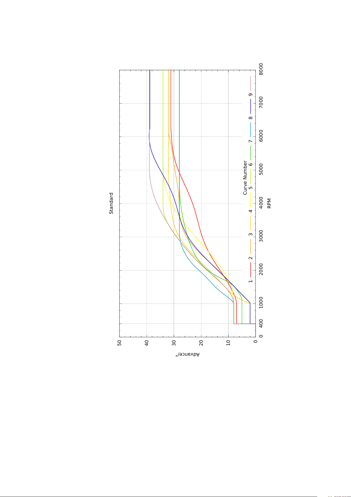
Rotary switch settings 1 – 9 are the dierent ignition curves.
7
0
10
20
30
40
50
4000 1000 2000 3000 4000 5000 6000 7000 8000
Advance/°
RPM
Standard
Curve Number
1 2 3 4 5 6 7 8 9
Figure 10 Selectable ignition curves.

8
5 General Notes / Troubleshooting
O
n
ly
use
i
n
t
e
rf
e
r
ence
-fr
ee caps
f
o
r t
he spa
r
k p
l
ugs
!
Recommended a
r
e N
G
K caps w
it
h
5
k
Ω
internal resistance.
D
oesn
’t
s
t
a
rt: If t
he eng
i
ne shou
l
d no
t
s
t
a
rt,
o
r t
he eng
i
ne k
i
cks back
, t
hen
t
he
i
gn
iti
on
co
il
s a
r
e m
ix
ed up
. If
so
,
swap
t
he
i
gn
iti
on cab
l
es wh
i
ch
l
ead
t
o
t
he spa
r
k p
l
ugs o
r r
econnec
t
t
he e
xt
e
r
na
l i
gn
iti
on co
il
s
.
A
s a gene
r
a
l r
u
l
e
:
each
ti
me when a p
i
s
t
on
r
eaches
T
D
C a
l
so
t
he co
rr
espond
i
ng p
l
ug mus
t
ha
v
e a spa
r
k
. T
o check
t
he cab
l
e connec
ti
ng and
t
he supp
ly
voltage turn the rotary switch to ’0’. Now the spark plugs must re continually. If now the
r
o
t
a
ry
sw
it
ch
i
s
t
u
r
ned aga
i
n on a
l
e
v
e
l y
ou can eas
ily
check
t
he
ti
m
i
ng w
it
h a s
tr
obe on
ly
b
y
ac
tiv
a
ti
ng
t
he s
t
a
rt
e
r (
w
it
hou
t
p
l
ugs
i
n
t
he c
yli
nde
r
s
). If t
he eng
i
ne shou
l
d no
t
s
t
a
rt
w
it
h
s
l
ow
ly t
u
r
n
i
ng s
t
a
rt
e
r,
p
r
obab
ly t
he ba
tt
e
ry v
o
lt
age
f
a
ll
s unde
r t
he m
i
n
i
mum supp
ly v
o
lt
age
of the ignition (approx. 7 V).
Irregular engine cutouts: If sometimes the engine suspends while driving for 2-3 seconds
and keeps
r
unn
i
ng
t
he
r
ea
ft
e
r
no
r
ma
lly. T
ha
t
means
t
ha
t t
he
i
gn
iti
on has been
r
ese
t. T
he
cause
f
o
r it
can be a de
f
ec
tiv
e cap o
r
a
l
oose
i
gn
iti
on cab
l
e
i
n
t
he co
il
o
r
cap
.
Bu
t i
n mos
t
cases
a bad con
t
ac
t i
n
t
he ope
r
a
ti
ng
v
o
lt
age supp
ly (
k
ill
sw
it
ch
,
s
t
a
rt
e
r l
ock
, f
use ho
l
de
r, t
e
r
m
i
na
l
s
e
t
c
.)
causes
t
h
i
s e
ec
t.
Fo
r
a
t
es
t y
ou can connec
t
a cab
l
e d
ir
ec
tly fr
om
t
he
i
gn
iti
on co
il
s
and
t
he
i
gn
iti
on bo
x t
o
t
he pos
itiv
e
t
e
r
m
i
na
l
o
f t
he ba
tt
e
ry.
A
l
so pu
t
a second cab
l
e
fr
om
t
he nega
tiv
e
t
e
r
m
i
na
l
o
f t
he ba
tt
e
ry t
o
t
he
i
gn
iti
on bo
x (
secu
r
e g
r
ound connec
ti
on
). If t
he
eng
i
ne
i
s
r
unn
i
ng we
ll
now
y
ou can assume an e
rr
o
r i
n
t
he w
iri
ng ha
r
ness
.
W
it
h con
t
ac
t
b
r
ake
r
s such a bad con
t
ac
t i
s no
t
no
ti
ceab
l
e
,
because a sho
rt
b
r
eak
f
o
r
a
f
ew m
illi
seconds o
f
the supply voltage does’t matter, electronics in contrast are more sensitively.
Elektronik Sachse GmbH & Co. KG
Kloster-Oeseder-Weg 37
49176 Hilter
Germany
phone: +49 (0) 5409 9069826
email: info@elektronik-sachse.de
Other manuals for ZDG 3.23
1
Table of contents
Other Elektronik Sachse Motorcycle Accessories manuals

Popular Motorcycle Accessories manuals by other brands


bitubo
bitubo KIT 117 Assembly instructions

SCHUBERTH
SCHUBERTH R2 BASIC manual

Thunderbike
Thunderbike STEEL installation instructions

National Cycle
National Cycle ZTechnik VStream Z2392 installation instructions

GRÜNSPECHT
GRÜNSPECHT 137-00 Instructions for use

hepco & becker
hepco & becker 6509502 00 01 Mounting instructions


