12
EN
Operating and assembly instructions HRD www.elektror.com
016309 03.14/08
2 INFORMATION ON TRANSPORT,
HANDLNG AND STORAGE OF THE
MACHINE
2.1 Transportation and handling
• Before installation and putting into service, check all parts
for transit damage. A damaged blower is a potential safety
hazard and, therefore, should not be put into service.
• Do not leave the blower unprotected in the open
(protect against ingress of moisture).
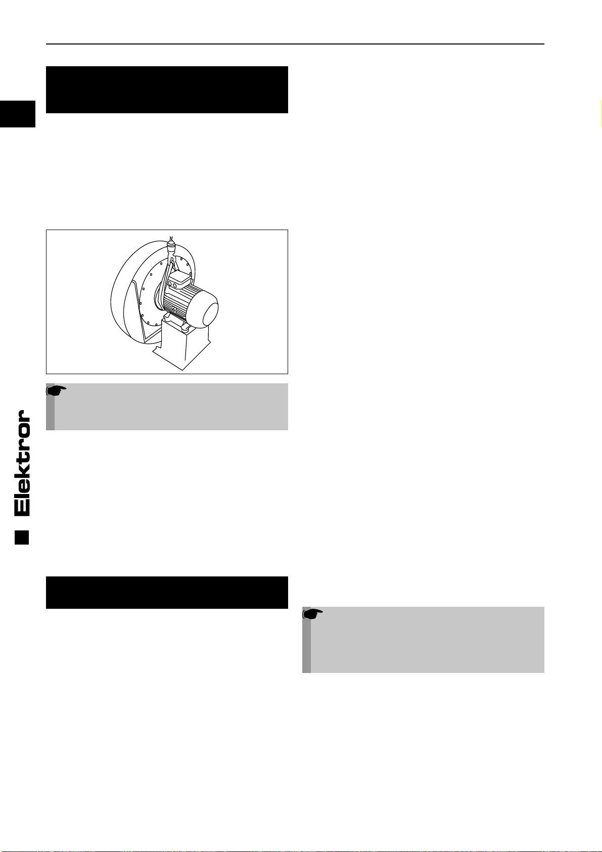
• Attach hoisting gear securely. Only use hoists and load
suspension devices with sufficient load-carrying capacity.
Secure the route of transportation.
Note!
The eye bolt on the motor must not be used to lift
the entire blower. This is used if the motor needs
to be (dis-)assembled.
2.2 Storage
• Ensure that the air intake connection and pressure connec-
tion are closed.
• Store the blower
-> in its original packaging if possible
-> in a closed room
-> in a dry, dust-free and vibration-free area.
• Storage temperature range from -20°C to +60°C
• After a storage period of 6 months, the blower bearings
and/or motor bearings should be checked before they are
mounted in the blower.
3 INFORMATION ON COMMISSIONING
THE MACHINE
3.1 Installation and assembly
• Protect the blower from the weather and install it in a
horizontal position, see also 1.1. For outdoor use, protec-
tion from the weather must generally be provided that
fulfils the requirements listed in 1.1 Intended Use and
protects the blower from the influences of the weather.
• Do not subject the blower subsequently to vibration or
impact loads during operation. Permissible vibrational load
on blower: refer to ISO 14694, BV-3.
• Standard blowers with base: Bolt securely to a level
and firm surface at the place of use, making sure that the
surface has adequate load-bearing capacity and avoiding
vibration transmission or vibrational load.
• Standard blowers without base:
At the place of use, bolt the blower securely to a fixed
base having sufficient load capacity without transmitting
vibrations or vibrational load. In the case of HRD blowers
with suction and/ or pressure side connections, this is
possible with the following types:
up to max. HRD 1/5T or HTD 1T FU(K)-105/1,1,
up to max. HRD 14/5T or HTD 14T FU(K)-105/2,2,
up to max. HRD 2/3T or HTD 16T FU(K)-105-2,2 and
up to max. HRD 2T FU(K)-95/3,0.
• Blower units without motor and belt drive belt guard with
these models, the supplied blower base is intended only
for set-up of the blower unit. The purchaser (plant
engineer, operator or other customer) is responsible for
the secure and stable installation and attachment of the
blower in combination with the motor, belt drive and belt
guard to be supplied by the purchaser in compliance with
the applicable standards and regulations.
• Installation of standard blowers with a vertical drive shaft
is possible with HRD blowers up to the following models:
with flange housing: maximum to HRD 2/5T
FU/FUK blowers: maximum to HRD 60 FU(K)-105/4,0
maximum to HRD 65 FU(K)-100/4,0
• Cover open intakes or outlets with protective grating to
DIN EN ISO 13857.
• Make sure that adequate motor ventilation is provided.
Permissible ambient temperatures:
Standard version with rated voltage (max. +/-10% voltage
tolerance) and a design frequency of 50Hz or 60Hz.
• Ambient temperature -20°C to +60°C
Special voltages, multi-voltage motors, FU compatible
versions, FUK versions, UL certified appliances:
• Ambient temperature -20°C to +40°C
The performance of the drive motor’s ventilation system must
not be impaired by the installation situation.
3.2 Blower units without motor and belt drive
During assembly of the blower with the motor, belt drive and
belt guard supplied by the purchaser, in addition to the in-
structions given in Chapter 1, the purchaser / operator must
pay attention to the following:
• Exact alignment of the belt pulleys
• Exact axial parallelism of the belt pulley axes
• Correct belt type and belt tension
• Max. permissible forces
• The V-belt pulleys must be free from burrs, rust and dirt
• Correct V-belt profile and belt pulley type
• Max. permissible blower speeds
You will find the data relevant to your appliance tabulated in
section 11 and in section 5.4 (where applicable).
3.3 Electrical connection
Note!
The work described in this section may only be
performed by a qualified electrician. Connect the
appliance as per the circuit diagram in the termi-
nal box and in accordance with the relevant local
requirements.
Three-phase or a.c. motors can be used as drive motors.
In the appliance designation, the letter D stands for three-
phase a.c. and the letter E for single-phase a.c.
• The drive motor must be protected using a motor overload
switch (this does not apply to frequency converter operated
appliances). Where appliances are frequency-converter-op-
erated, the existing temperature sensor (PTC resistor sen-
sor) or temperature switch (normally closed contact) must be
connected to the converter and evaluated.
• Check that the mains voltage matches the ratings on the
nameplate.
• The safety earth terminal can be found in the terminal box.


