Elements RO-6-BF User manual

Hankscraft, Inc. 300 Wengel Drive Reedsburg, WI 53959
“Innovative Solutions for Your Water”
RO-6-BF and RO-6-BF-NF

Table of Contents
Introduction 2
System Contents 3
Filtration Stages 4
Pre-Installation 5-6
Connecting standard quick connection push-in fittings 6
Disconnecting standard quick connection push-in fittings 6
System Installation 7-9
Step 1: Tapping into cold water supply 7
Step 2: Installing the dispensing faucet 8
Step 3: Mounting the tank ball valve 8
Step 4: Mounting the drain saddle valve 9
Step 5: Pressure testing and purging 9
System Care and Maintenance 10-12
Pre-filter Change-out Procedure 10
Post filter Change-out Procedure 10
Membrane Change-out Procedure 11
Filter Replacement Chart 12
Connection Diagrams 13-15
6-Stage RO Flow Chart 13
6-Stage RO with Booster Pump Flow Chart 14
6-Stage RO with Permeate Pump Flow Chart 15
Troubleshooting 16
System Specifications 17
Performance Data Sheet 18
Warranty 19
Arsenic Facts Sheet 20
Contact Information 21
1

Congratulations!
Thank you for choosing our Elements Bluefilters Reverse Osmosis Drinking Water Filter System. You now own the world’s
finest water filtration system.
This system uses household water pressure to reverse a natural physical process called osmosis. Water is forced through a
semi-permeable membrane where unwanted constituents are filtered out, sending only clean drinking water to the
faucet.
The system includes innovative and patented NewLine replaceable pre-filters which use cutting-edge technologies and
convenient post-filter cartridges. These pre-filters remove sediment and chlorine from the water supply before they can
enter the RO membrane. The post-filter removes any taste or odors that may remain in the water after passing through
the RO membrane and just before going to the faucet. To prevent water waste, an automatic shut-off valve closes when
the RO faucet is closed and the storage tank is full.
This reverse osmosis system will provide you with a continuous supply of sparkling clear, delicious water for drinking,
cooking and other uses. Foods will look and taste better, too. Having high-quality RO water at your sink eliminates the
need to buy bottled water saving you money and reducing your footprint on the environment.
Bluefilters –when only the best is good enough
Bluefilters is a leader in production of water filtration systems.
The high quality of these systems is based on patented, innovative German technology.
2

Please Note
Please read through the instructions before proceeding with the installation. Be sure to follow all applicable
national, state, county and local plumbing codes and regulations. With proper care, your reverse osmosis
system will produce high-quality, great tasting water for many years. See the Performance Data Sheet for
more information.
SYSTEM CONTENTS:
1. Reverse osmosis unit
2. Water storage tank
3. One length of ¼" tubing
4. Installation kit
5. Tank ball valve
6. Drain saddle valve
7. Brass water feeder with valve
8. Faucet with assembly kit
9. Installation manual
TOOLS NEEDED:
1. Variable speed drill
2. ¼" & ½" drill bits
3. Adjustable wrench, pliers
4. Screwdriver
5. Utility knife or scissors
6. Teflon tape
Caution!
This reverse osmosis system contains many replaceable components critical to the efficiency of the system.
Replacement of any component should be with one of supplied by the manufacturer to ensure the same
efficiency and contaminant reduction performance.
3

3
4
Stage 1 - Sediment Cartridge- p/n AC-PS-10-NL
Water from the cold water supply pipe enters the RO sediment filter first. This sediment cartridge is the best solution
to remove impurities such as sand, silt and other sediments that you may or may not be able to see in your water.
Stage 2 –Activated Carbon Cartridge- p/n AC-GAC-10-NL
The activated carbon cartridge uses the advantages of granulated activated carbon absorption abilities. It removes
even smaller sediments (invisible to human eye) as well as chlorine. Sediment and/or chlorine can destroy the RO
membrane and this filter provides polished, filtered, chlorine-free water to the RO membrane to protect it. It also
improves taste, color and odor of water.
Stage 3 –Sediment-Carbon Cartridge- p/n AC-sC-10-NL
The sediment/carbon cartridge removes any remaining bad tastes and odors from the water as well as chlorine
which can damage the RO membrane.
Stage 4 - Reverse Osmosis Membrane- p/n AC-OM-75-FILMTEC
The RO membrane removes dissolved solids when the water is forced through the cartridge. High quality water exits
the RO cartridge to the storage tank, post-filter and RO faucet. Rejected water is routed through the flow control
valve to the drain.
Stage 5 - Post RO Carbon Cartridge- p/n AC-IL-GAC-S
Made of high quality activated carbon which enhances the flavor and taste of the water, this post-filter removes any
remaining tastes or odors from the RO filtered water.
Stage 6 –Post RO Mineralizing Cartridge- p/n AC-IL-MIN-S
The mineralizing cartridge contains different kinds of minerals which will dissolve into the water to return a
calibrated amount of taste back to the water.
Automatic Shut-off Valve Assembly- p/n AP-ASV-04-JG-S
To ensure proper system operation, this drinking water system has an automatic shut-off valve system. When the
storage tank is filled to capacity and the RO faucet is closed, pressure closes the shut-off valve to stop the flow to
drain. After drinking water is used and pressure in the system drops, the shut-off valve opens to allow water to flow
again.
Storage Tank- p/n (contact Hankscraft)
The storage tank holds processed RO water. A diaphragm inside the tank keeps water pressurized to about 30 psi
when tank is full. This pressure provides a fast flow to the RO faucet. The tank is pressurized to 5-7psi when empty.
Permeate Pump (optional)- p/n RO-PP-BF
This pump is used to increase the efficiency of your RO system. It reduces the amount of water used in the
purification process by balancing the relation between the amount of purified water and water released into the
drain. This pump does not require electricity or any other power source.
Booster Pump (optional)- p/n RO-BP-BF
This 24VDC pump is used to increase the water pressure to the RO membrane. It comes with an internal pressure
switch for on-demand function and a high pressure safety switch to ensure operation only when water is supplied to
the system.

5
Pre-Installation Notes
This RO system is designed for installation under the sink, usually in the kitchen or bathroom. It can be mounted on a wall
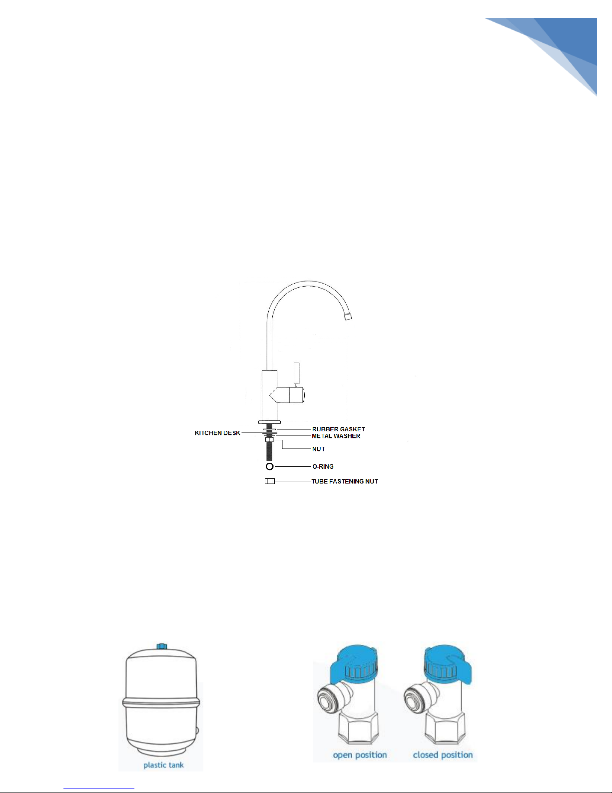
surface or on the cabinet floor next to the storage tank. The RO faucet installs on the sink or into the counter next to the
sink. You can also install the system in any remote location from the faucet, observing the safety guides below. You will
need a nearby water supply and drain point.
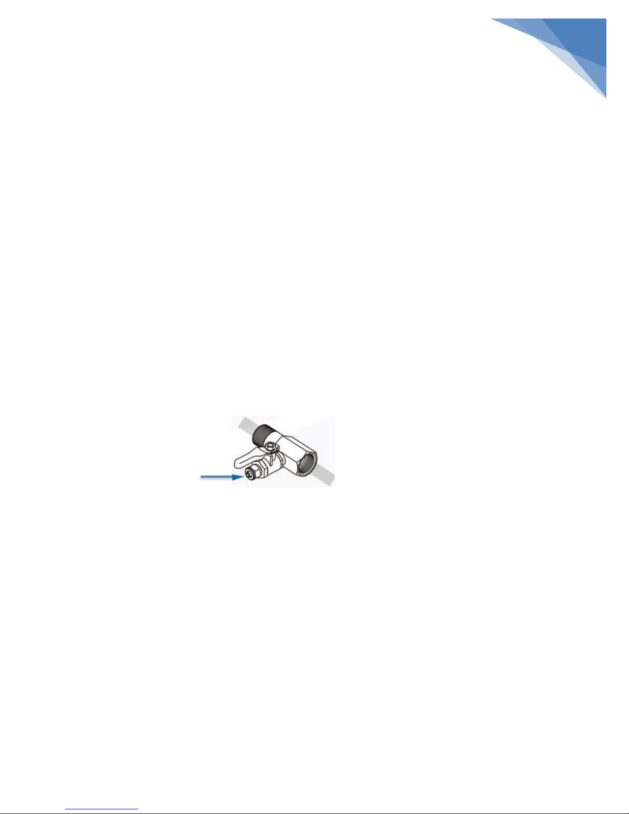
Water Supply: To provide supply water to the RO system, use the included feed supply fittings as described on page 7.
Drain Point: A suitable drain point is needed for the reject water from the RO membrane. A floor drain, laundry tub,
standpipe, sump, etc., is preferred for remote installations. A saddle drain adapter is included to install the system under
the sink where codes permit it as an optional drain point.
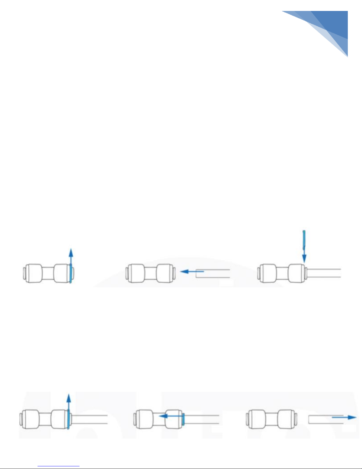
NOTE: Tubing lengths supplied with the system allow for easy moving of the filter assembly for servicing. If tubing
lengths are shortened for a neater appearance, it may be necessary to keep the filter assembly in its installed
location for service. Please keep connecting tubes as long as possible for convenient usage.
CAUTION: A refrigerator icemaker may not operate properly when connected to an RO system that has been
installed on a water system operating outside of the specified pressures listed on the Performance Data Sheet.
CHECK YOUR WATER SUPPLY: The COLD water supply to the RO system must be within certain quality limits. See
the Performance Data Sheet. If the supply water is not within the limits defined, the RO system will not filter
water as it should and will substantially reduce the filter and membrane life.
CAUTION: Chlorine in water will destroy the RO membrane. Most municipalities add chlorine to the water supply
to kill water-borne infectious organisms. The pre-filters will remove the chlorine up to the limits shown in the
Performance Data Sheet before it enters the RO membrane. It is important to replace the pre-filter cartridges at
the recommended time intervals. See the filter change-out procedures and the Performance Data Sheet.
CAUTION: Before consuming any water from the RO system you must purge the RO membrane cartridge. The RO
cartridge contains a food grade preservative that should be removed before consuming the water from the
system. This procedure is explained on page 11.
DO NOT attempt to use this product to make safe drinking water from non-potable water sources. Do not use the
system on microbiologically unsafe water, or water of unknown quality without adequate disinfection before or after the
system. This system is suitable for cyst reduction and may be used on disinfected water that may contain filterable cysts
per the Performance Data Sheet.
Check with your local public works department for applicable plumbing and sanitation codes. You must follow their
guides as you install the system. Follow your local codes if they differ with guidance in this manual.
This reverse osmosis system works on water pressure of 40 psi minimum to 87 psi maximum. You must install a
pressure reducing valve in the water supply pipe to the reverse osmosis system if the water pressure exceeds 87 psi.
DO NOT install this reverse osmosis system outdoors or in extreme hot or cold environments. Temperature of the feed
water supply to the RO system must be between 39⁰ F to 100⁰ F. Do not install on hot water.

Pre-Installation Continued
This RO system uses quick connection push-in fittings. These fittings only require a firm push to connect the tube.
Connecting Standard Quick Connection Push-in Fittings
Step 1: Remove locking clip from the fitting as shown in Fig. 1
Step 2: Push tube into the fitting (Fig. 2). The collet (gripper) has stainless steel teeth which hold the tube firmly in
position while the O-ring provides a permanent leak-proof seal. Pull on the tube to verify it has been
secured. It is a good practice to test the system prior to leaving the site and/or before use.
Step 3: Place the locking clip back (Fig. 3) to lock the tube and prevent it from accidental slip-out.
Figure 1 Figure 2 Figure 3
Disconnecting Standard Quick Connection Push-in Fittings
Caution! Make sure that the system is depressurized before removing fittings.
Step 1: If present, remove locking clip from the fitting as shown in Fig. 4.
Step 2: Push in the collet against the face of the fitting (Fig 5). With the collet held in this position the tube can
be removed (Fig. 6). The fitting can then be re-used.
Figure 4 Figure 5 Figure 6
6

Installation
Step 1: Tapping Into Cold Water Supply
Caution! The water supply to your RO unit MUST be from a COLD water line. Hot water will severely damage your RO
system.
Brass Water Feeder 3/8" –Water Supply Connection:
1. Locate cold water shut-off valve under the sink or main shut-off valve and turn it off. Open the cold water faucet
to release the pressure and make sure there is no water running.
2. Untighten compression nut or under sink shut-off valve. Place supplied gasket and install connector element.
Tighten firmly.
3. Take the ball valve and mount it on the connector element.
4. Connect the supplied line or under sink shut-off valve back to the connector element. Turn the ball valve handle to
close position and open main or cold water shut-off valve and check for any leaks.
5. Use the Teflon tape for sealing the threaded ends.
6. Connect ball valve with the RO system with ¼" plastic tube, which is a part of the RO system installation kit. Please
refer to connection schemes at the end of this manual for appropriate connection.
Connection to RO System Water Supply Line
Step 2: Installing the Faucet
The faucet should be positioned with aesthetics, function, and convenience in mind. An ample flat surface is
required for the faucet base so that it can be installed firmly. Also, check the underside of the sink in the desired
location to see if there is enough space to complete the faucet installation.
If there is not enough space available on the upper sink area, the faucet could be positioned on the counter top at
the edge of the sink. Be sure to watch for obstructions below. i.e., drawers, cabinet walls, support braces, etc. If
the counter top is made of ceramic tile, the method for drilling the hold should be the same as for a porcelain sink.
Note: The sink drilling process, although not complicated, requires a certain amount of caution and forethought. A
porcelain sink can crack if care is not exercised.
Drilling a Porcelain Enamel Sink / Stainless Steel Sink / Aluminum Sink:
A ½" hole is required for the faucet. It is recommended that you obtain a special ceramic drill bit for a porcelain
sink and tile counter. When drilling the faucet hole for the sink or counter, you should wear eye protection and
exercise caution by carefully following the steps below:
7

8
1. Place a piece of masking tape or duct tape on the determined location where the hole is to be drilled.
2. Use a variable speed drill at slow speed with ¼" drill bit and drill a centering hole in the center of the desired
faucet location. Use lubricating oil to keep the drill bit cool while drilling.
3. Enlarge the hole using a ½" drill bit. Keep bit well-oiled and cool, drill slowly.
4. File or clean the surrounding area and then remove the masking or duct tape. Caution! The metal chips on
porcelain will stain very fast.
5. Place the chrome cover plate and the rubber washer onto the threaded mounting tube at the base of the
faucet before placing in drilled hole.
6. From under the sink, install the white plastic locating washer, the small metal washer and screw on the nut
until it is tight against the underside of the sink or counter.
7. With all fittings in place, thread the tube fastening nut and collet. Insert the tubing into the faucet inlet and
tighten the nut.
8. Connect the other free end of the ¼" tubing to the post filter. Please refer to connection diagrams at the end
of this manual for appropriate connection.
Step 3: Mounting the Tank Ball Valve
NOTE: Do not tamper with the air valve on the lower side of the storage tank. Factory preset to 5-7 psi
1. Remove the plastic cap on top of the tank.
2. Put Teflon tape around the thread.
3. Connect the ball valve to the thread. Hand-tighten only. Do not use a wrench or over tighten it.
4. Connect ¼" tubing to the ball valve and connect the other free end of the ¼" tubing to the post filter.
CAUTION! Be careful not to damage plastic thread of the tank ball valve.

9
Step 4: Mounting the Drain Saddle Valve
1. The drain saddle valve will fit most 2" standard plastic drain pipes. It should be installed above the trap and on the
vertical or horizontal pipe under the sink drain.
2. Remove the nuts and bolts from the front half of the saddle valve. Position and hold it in the desired location on
the drain pipe above the trap and water line. Mark the spot for drilling with a 5/32" drill bit or awl through the
hole in the clamp. Do not mount the saddle valve next to a garbage disposal, as this may cause the drain line to
clog. You should carefully consider the route and available space for the ¼" poly drain line tubing before you drill
the ¼" hole.
3. Where you marked the location in Step 1, drill a ¼" hole into the drain pipe and clean the surface of the pipe.
4. Align the drilled hole in the drain pipe with the front half of the saddle valve using the 5/32" drill bit or a narrow
screwdriver.
5. Locate the complementary piece of the saddle valve assembly clamp and join them together with the two bolts.
Tighten the bolts evenly.
6. Connect ¼" tubing to drain saddle valve and the other free end to the flow restrictor valve. Please refer to
connection diagrams at the end of this manual for appropriate connection.
Step 5: Pressure Testing and Purging
1. Check all tubing to be sure there are no kinks or obstructions.
2. Turn the storage tank valve to the OFF position.
3. Turn RO faucet lever to continuous flow ON position (handle pointed up).
4. Turn the cold water supply valve on slowly. When the system is pressurized, check for leaks.
5. You will hear the air purging from the system. Within 5 minutes the water should start dripping from the RO
faucet. Once the water starts to drip, allow 20 more minutes for the water to flow through the system and purge
trapped air.
6. After 10 minutes, turn the storage tank valve to the ON position (handle is parallel to the tubing).
7. Turn the RO faucet handle to the OFF position. Now the purified water will start going into the storage tank.
8. CAUTION! You must purge the first two tanks of water from the system prior to consumption of the product
water. Do not drink the first 2 tanks of water produced by the system!
9. Allow the storage tank to fill for 2 hours. Then open the faucet until the tank is empty and the flow just drips from
the faucet.
10. Close the faucet and allow the storage tank to fill again for 2 hours. Then open the RO faucet and empty the tank
again. After discharging the contents of the storage tank twice, you can start enjoying the pure water.
11. NOTE: Check for leaks daily for the first week after installation.

10
Filter Change-out Procedures
Pre-filter Replacement (lifetime: 3-6 months)
To change the pre-filters, follow these instructions.
CAUTION! Use only Hankscraft Bluefilters NewLine replacement filters and membranes. Using any other filters
will cause severe damage to the system, void all warranties and potentially damage the surrounding area.
1. Shut off the feed water supply to the system by turning the saddle valve on the water supply clockwise until it
stops.
2. Close the storage tank ball valve by turning the handle perpendicular to the valve body.
3. Press down on the faucet handle to release pressure.
4. Allow 3-5 minutes for pressure in the system to drop.
5. Turn the cartridge counter-clockwise to loosen it and remove the cartridge from the head (cap). Be careful as the
cartridges are filled with water.
6. Unpack new cartridges from any protection foil and line up the new cartridge with the center of the head.
7. Turn the cartridge clockwise to tighten it.
8. Turn on the feed water supply to the system.
9. Turn the RO faucet on to rinse the new cartridge for 15 minutes before using the water.
10. Open storage tank ball valve.
11. CAUTION! A higher frequency of filter changes may be necessary, dependent upon your feed water quality. You
should inspect the filters periodically and maintain a service record, using the chart located later in this manual, to
establish a maintenance schedule that is unique to your water conditions.
Post-filter Replacement (lifetime: 6 months)
To change the post-filter, follow these instructions.
1. Shut off the feed water supply to the system by turning the saddle valve on the water supply clockwise until it
stops.
2. Close the storage tank ball valve by turning the handle perpendicular to the valve body.
3. Press down on the faucet handle to release pressure.
4. Allow 3-5 minutes for pressure in the system to drop.
5. Remove the ¼" tubing from the ends of the post-filter you want to change by following the instructions on page 6
of this manual.
6. Now, using an adjustable wrench, remove the male adaptor and tee on each end of the post filter and dispose of
the filter properly.
7. Unpack new post-filter from any protection foil.
8. Wrap the threaded end of each fitting with Teflon tape (male adaptor and tee) and use an adjustable wrench to
screw them into the new post-filter.
9. Reattach the ¼" tubing to the male adaptor on the left end of the post-filter. Reattach the ¼" tubing to the tee on
the right end of the filter. Lastly, reattach the ¼" tubing auto shut-off line to the tee. Snap the filter back into the
membrane clips. Please refer to the system scheme at the end of this manual for appropriate connection.
10. Turn on the feed water supply to the system.
11. Turn the RO faucet on to rinse the new cartridge for 15 minutes before using the water.
12. Open storage tank ball valve.

11
Membrane Replacement (lifetime 2-5 years)
To change the membrane, follow these instructions.
1. Shut off the feed water supply to the system by turning the saddle valve on the water supply clockwise until it
stops.
2. Close the storage tank ball valve by turning the handle perpendicular to the valve body.
3. Press down on the faucet handle to release pressure.
4. Allow 3-5 minutes for pressure in the system to drop.
5. Remove the ¼" tubing from the cap end of the membrane housing by following the instructions on page 6 of this
manual.
6. Unscrew the membrane cap by turning it counter-clockwise until it is completely removed. Be sure that the O-ring
remains properly seated on the collar of the housing.
7. Unpack the membrane from any protection foil.
8. CAUTION! Use food-grade silicone grease for membrane seals before membrane installation.
9. With a pair of pliers, gently grab the membrane plastic tube end and pull it out. This procedure may require a little
back and forth twisting and pulling motion, as the membrane is press-fitted into the housing. Be careful not to
damage the inside walls of the membrane housing.
10. Insert the new membrane into the membrane housing and use your thumbs to apply pressure to the membrane in
the direction shown making sure the brine seal and permeate O-rings seat into the housing completely.
11. Turn on the feed water supply to the system.
12. Turn the RO faucet on to rinse the membrane for 20 minutes before using the water.
13. Open storage tank ball valve.
Insert new membrane into the housing in this direction
Feed Water
Figure 13 –Regular Membrane Scheme
Filter Lifetimes:
NewLine Pre-filters –3-6 months
NewLine Post filters –6 months
NewLine RO membrane –2-5 years
NOTE: Regularly (i.e. once per month) check your TDS* level of feed water and purified water. Results will keep you
updated about the filtration efficiency and the filter condition. RO membrane should lower TDS value of the feed
water by around 90%. If the TDS level of purified water is out of range the pre-filters, post filters, and/or membrane
should be replaced.
*TDS (Total Dissolved Solids) –total content of substances dissolved in water measured in ppm (parts per million = mg/L)
Purified Water

12
Filter Replacement Date Chart
Installation Date:
Stage 1
Stage 2
Stage 3
Stage 4
Stage 5
Stage 6

13
Standard RO System Flowchart
PARTS LIST:
A-Sediment Cartridge p/n AC-PS-10-NC
B-Activated Carbon Cartridge p/n AC-GAC-10-NL
C-Sediment/Carbon Cartridge p/n AC-SC-10-NL
D-RO Membrane p/n AC-OM-75-FILMTEC
E-Storage Tank (3gal)
F-Inline Carbon Cartridge p/n AC-IL-GAC-S
G-Inline Mineralizing Cartridge p/n AC-IL-MIN-S

14
RO System with Booster Pump Flowchart

15
RO System with Permeate Pump Flowchart

16
Troubleshooting
Taste and/or Smell of Chlorine in Clean Water
Cause: Concentration of chlorine in feed water is above the limit, which damaged the membrane. Pre-filter does
not work or does not remove chlorine from feed water.
Solution: If the concentration of chlorine in feed water is above 2.0 ppm an additional pre-filtration stage should
be used. Replace the pre and post filters, membrane and flow restrictor.
Changed Smell and Taste of Clean Water
Cause: Used post-filters. Used membrane. Storage tank contains unfiltered water.
Solution: Replace the post-filter. If the smell and taste lingers, replace the membrane and flow restrictor. Disinfect
the whole system and storage tank.
Low System Capacity
Cause: Pre-filters or membrane are clogged with sediments. Feed water does not comply with the standard
requirements.
Solution: Replace the pre-filters. If the capacity does not improve, replace the post-filters, membrane and flow
restrictor. Increase water pressure, carry out additional filtration, etc. before doing the service.
Filtration Speed is Lower than Usual
Cause: Water pressure in the storage tank is below 5-7 psi.
Solution: Open the faucet valve and empty the tank completely. Check the pressure in the storage tank (keeping
the faucet valve open). If the pressure is low, increase it up to 0.4 bar (6 psi). Close the faucet in order to fill the
tank.
High TDS Value of Clean Water
Cause: Feed water does not comply with the standard requirements. Used membrane.
Solution: Increase water pressure, carry out additional filtration, etc. Replace the pre-filters, membrane and flow
restrictor.
Constant Water Flow to the Drain
Cause: Shut-off valve is clogged.
Solution: Clean or replace if necessary.

17
System Specifications
RO-6-BF and RO-6-BF-NF
Parameters
Minimum
Maximum
Operating Temperature
39˚F
100˚F
Operating Water Pressure
40 psi
87 psi
pH
2
11
Iron
0 ppm
0.2 ppm
Hardness
0 grains
10 grains
TDS
0 ppm
1500 ppm
Chlorine
0 ppm
2.0 ppm
RO System Modules
p/n
Change
Every
Stage 1- Sediment Filter
AC-PS-10-5-NL
3-6 mo.
Stage 2- Activated Carbon Filter
AC-GAC-10-NL
3-6 mo.
Stage 3- Sediment and Carbon Filter
AC-SC-10-NL
3-6 mo.
Stage 4- RO Membrane
AC-OM-75-FILMTEC
2-5 yrs.
Stage 5- Activated Carbon Filter
AC-IL-GAC-S
6 mo.
Stage 6- Remineralization Cartridge
AC-IL-MIN-NL
3-6 mo.
System Performance
Daily Production Rate
27.94 gpd
Efficiency Rating
14.05%
Recovery Rating
30.44%
RO Filtration Unit
Height
17"
Width
13 7/8"
Depth
5 7/8"
Weight
15 lbs.
Storage Tank
Height
16 1/2"
Diameter
9 1/4"
Weight (empty)
6.5 lbs.
Weight (full)
31.5 lbs.
Capacity
3 gal
Note: This system is to be used with municipal or well water sources treated and tested on a regular basis to ensure bacteriological
safe quality. DO NOT use with water that is microbiologically unsafe or unknown quality without adequate disinfection before and
after the system. Systems certified for cyst reduction may be used on disinfected water that may contain filterable cysts.
Depending on water chemistry, water temperature and water pressure, Elements by Hankscraft’s Bluefilters RO system production
and performance will vary. Efficiency rating means the percentage of the influent water to the system that is available to the user as
reverse osmosis treated water under operating conditions that approximate typical daily usage. Recovery rating means the percentage
of the influent water to the membrane portion of the system that is available to the user as reverse osmosis treated water when the
system is operated without a storage tank or when the storage tank is bypassed. There is an average 4 gallons of reject water for every
1 gallon of product water produced.

18
Performance Data Sheet
RO-6-BF and RO-6-BF-NF
This system has been tested according to NSF/ANSI 58 for reduction of the substances below. The concentration of the
indicated substances in water entering the system was reduced to a concentration less than or equal to the permissible limit
for water leaving the system as specified in NSF/ANSI 58.
Average Influent
Concentration
(mg/L)
Average
Effluent
Concentration
(mg/L)
Average
%
Reduction
Maximum
Effluent
Concentration
(mg/L)
Influent Challenge
Concentration
(mg/L)
Maximum
Allowed
Concentration
(mg/L)
Arsenic (Pentavalent)
0.29
0.002
99.3
0.003
0.3±10%
0.01
Barium
9.5
0.14
98.5
0.35
10.0±10%
2
Cadmium
0.031
0.0006
98.1
0.001
0.03±10%
0.005
Chromium
(Hexavalent)
0.30
0.007
97.7
0.013
0.3±10%
0.05
Chromium (Trivalent)
0.31
0.003
99
0.006
0.3±10%
0.05
Copper
3
0.038
98.7
0.069
3.0±10%
1.3
Cysts
11000 cfu/mL
6 cfu/mL
99.99%
32 cfu/mL
≥50,000 cfu/mL
99.95%
Fluoride
8.6
0.39
95.5
0.51
8.0±10%
1.5
Lead
0.16
0.003
98.1
0.019
0.15±10%
0.01
Radium 226/228
25 pCi/L
5 pCi/L
80
5 pCi/L
25 pCi/L
5 pCi/L
Selenium
0.1
<0.006
>94.0
<0.006
0.10±10%
0.05
Total Dissolved Solids
780
52
93.4
88
750±40 mg/L
187
Turbidity
11 NTU
0.1 NTU
98.9
0.4 NTU
11±1 NTU
0.5 NTU
Note: This system has been tested for the treatment of water containing pentavalent arsenic (also known as
As(V), As(+5) or arsenate) at concentrations of 0.30 or less. This system reduces pentavalent arsenic but may not
remove other forms of arsenic. For arsenic removal, this system is to be used on water supplies containing a
detectable free chlorine residual at the system inlet or on water supplies that have been tested to contain only
pentavalent arsenic. Treatment with chloramine (combined chlorine) is not sufficient to ensure the complete
conversion of trivalent arsenic to pentavalent arsenic. Please see the arsenic facts section on page 20 of this
manual for further information.

19
LIMITED WARRANTY
As described herein, Hankscraft Inc., d/b/a H20 Products (“Hankscraft”), warrants its products are free from defects in
material and workmanship only when properly installed, operated, and maintained. This warranty is subject to the exceptions
herein.
Hankscraft warrants to the original owner that the items listed below, excluding but not limited to, wear parts like O-rings,
gaskets, filters and seals, will be free from defects in materials and workmanship for the period of time specified below from
the original purchase date.
Control valves and all internal valve parts and the salt storage tank –FIVE (5) YEARS
Mineral tank –TEN (10) YEARS
Any other POE system component –ONE (1) YEAR
Ceramic disc for rotary valve (applicable to RevV series valves only) –LIFETIME
RO and UF Filter Systems- ONE (1) YEAR
Media/resin is not warrantied due to water supply quality differences
Any parts used for replacement are warrantied for the remainder of the original warranty period applicable to the part from
the date of manufacture so long as the parts are installed by a Hankscraft factory-trained and authorized installer.
Hankscraft’s obligation by this Limited Warranty, at its option, is to repair or replace any warrantied product only. Labor for
repair or replacement is not included as part of this warranty. Prior to returning the product to Hankscraft, a valid return
materials authorization (RMA) number must be obtained from Hankscraft. Any product returned to Hankscraft without a valid
RMA will be rejected. Any product found to be defective will, at the sole discretion of Hankscraft, be repaired or replaced.
Hankscraft is not responsible for shipping cost to the repair facility. This section lists the sole remedies for any valid warranty
claim.
This warranty does not apply to defects reported to Hankscraft outside of the warranty period.
This warranty does not apply to defects caused by installing, operating, servicing, modifying, repairing or maintaining (or lack
of maintaining) the product outside of Hankscraft’s recommendations. Filters, membrane elements and flow restrictors that
become fouled or plugged due to excessive turbidity, dissolved solids, or microorganisms are not covered by this warranty.
This warranty does not apply to defects caused by damage during shipment, neglect, misuse, modification, accident,
noncompliance with local codes and ordinances, hot water, frozen water, sediment, corrosive liquids, gases, chemicals,
bacteria, animals, sand, salt, flood, wind, fire, outdoor installations where the product is not reasonably covered, pneumatic
use, natural disasters, war, terrorism or acts of God. No other person is authorized to make any other warranty on behalf of
Hankscraft either during or after the applicable warranty period.
Hankscraft assumes no liability for determining the proper products and equipment or installation necessary to meet the
requirements of the user of the product, and Hankscraft does not authorize others to assume such liability on its behalf.
THE WARRANTIES AND REMEDIES HEREIN ARE EXCLUSIVE AND IN LIEU OF ANY AND ALL OTHER WARRANTIES OR REMEDIES EITHER
EXPRESSED OR IMPLIED, HEREIN OR ELSEWHERE, INCLUDING WITHOUT LIMITATION WARRANTIES OF MERCHANTABILITY, FITNESS
FOR ANY PARTICULAR PURPOSE, NON-INFRINGEMENT OR WARRANTIES RESULTING FROM COURSE OF PERFORMANCE, COURSE OF
DEALING OR FROM USAGE OF TRADE. HANKSCRAFT HEREBY DISCLAIMS ALL OTHER WARRANTIES. HANKSCRAFT’S LIABILITY SHALL
NOT EXCEED THE COST OF THE PRODUCT. HANKSCRAFT IS NOT RESPONSIBLE FOR INCIDENTAL OR CONSEQUENTIAL DAMAGES OR
EXPENSES OF ANY KIND WHATSOEVER, INCLUDING LOSS OF PROFITS, UNDER ANY CIRCUMSTANCES AND REGARDLESS OF WHETHER
HANKSCRAFT WAS AWARE OF THE POSSIBILITY OF ANY SUCH LOSS.
This manual suits for next models
1
Table of contents
Popular Water Filtration System manuals by other brands

DeWalt
DeWalt DXCM019-0352 quick start guide

Siemens
Siemens FDCL221 Technical manual

Panasonic
Panasonic ET-EMF320C operating instructions

Berkey
Berkey Go Berkey Kit manual

amiad
amiad Filtomat MG112 Installation, operation and maintenance instructions

Applied Membranes
Applied Membranes L Series Operation, maintenance & instruction manual