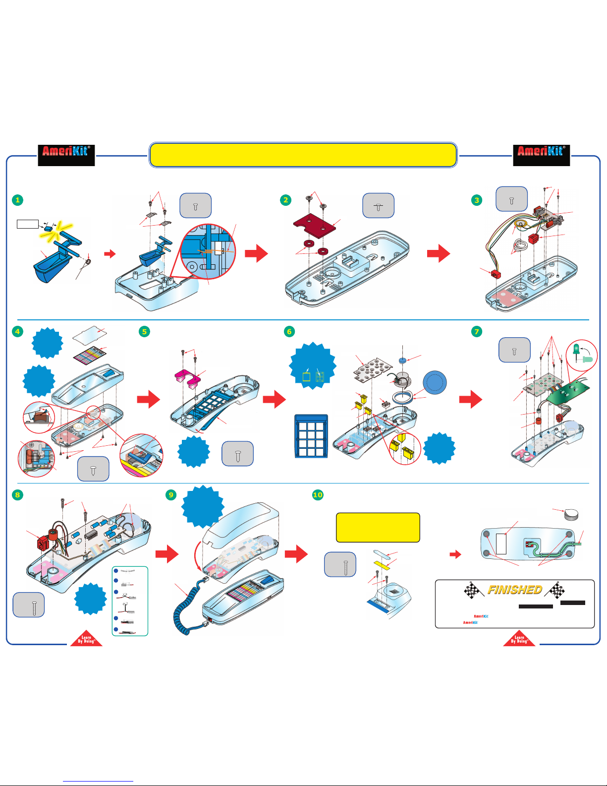
The AK-750 is a push-button pulse/tone dial electronic telephone kit that you put
together.The kit is mechanically and electronically assembled by the user with no
soldering required.
In addition to the experience of building the unit, there is also an overview of how
to use it, an electronic road map showing the electrical circuits, and a
troubleshooting section in case of problems.
The Model AK-750 is equipped with the following features:
1. Tone/pulse switch
2. Mute button
3. Automatic redial last number
4. Ringer ON/OFF switch
5. Neon bulbs flash as telephone is ringing
6. Lighted dial key pad
7. Flash button
8. Desk top or wall mounting
Recommended for ages 8 and up.It takes about 3 hours to build.
YOU WILL NEED:
• 9V battery (if you want to test while building).
• Scissors, sharp knife, or a pair of flush cutting diagonal pliers
• Screwdriver phillips medium size
TELEPHONE KIT
Manufactured by
Elenco®Electronics, Inc.
150 Carpenter Avenue
Wheeling, IL 60090
Copyright © 2005 Elenco®Electronics, Inc. Revised 2005 REV-B
WHATIT IS ELECTRONIC ROAD MAP
AK-750/FUN-755
2
753063
WARNING:
CHOKING HAZARD - Small Parts.
Not for children under 5 years.
Contains functional sharp edges
and points.
!!
HOW TO USE IT
Plug the telephone line into a modular jack connected to a telephone line.
1. Tone/Pulse Dialing - If your home is equipped with touch tone dialing service,
set the tone/pulse switch to tone position. If your home is equipped with rotary
dialing service, set the tone/pulse switch to pulse position.
2. Ringer ON/OFF Switch- The ringer can be turned OFF by setting the
RINGER ON/OFF SWITCH TO OFF.
3. ToPlace and Receive Calls - Lift handset to place or receive calls.Upon
completion, return handset to cradle, or press the hook switch or FLASH
BUTTON once if you want to make another call.
4. Last Number Redial - Whether or not you complete a call, the number dialed
is retained in memory until a new number is dialed. Just press to get new dial
tone then redial button. Y
our telephone remembers the last number dialed even
overnight. If you do not want anyone to know which number you dialed last,
pick up the phone and press any number, and hang up.
5. Mute Button - Allows you to hear the other party without them hearing you. To
use the MUTE function, press the mute button. Release the button to return to
normal. If your telephone is wall mounted to temporarily rest the handset
without hanging up, during a conversation, place on top TAB.
6. Flash Button - When you are finished with a call and wish to make another
press the FLASH BUTTON to obtain a dial tone.If you have CALL WAITING
(a custom calling feature) and wish to access a second call, press the FLASH
BUTTON. Press the FLASH BUTTON again to return to the first call.
7. Y
our telephone has neon bulbs to give a visual indication that it is ringing. The
LEDs illuminate the dial key pad.
34
78
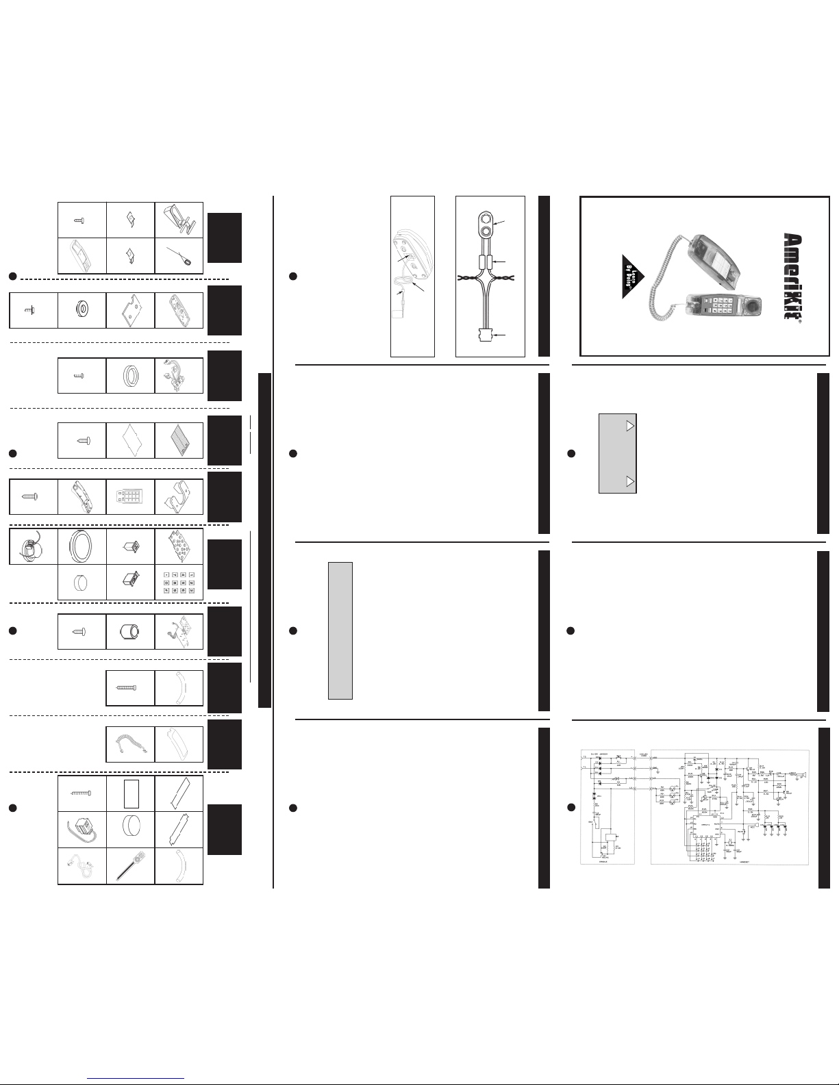
(SCHEMATIC DIAGRAM)
HOW IT WORKS
The telephone was invented in 1876. The primary purpose of the telephone is to
transmit and receive voice signals allowing two people with telephones to
communicate with each other. To be of practical value, the telephone must be
connected to a switching. Each subscriber telephone is connected to the
telephone company's Central Office (CO) by two wires referred to as the "Local
Loop." A simplified diagram of this connection is shown in the Block Diagram.
The TIP and RING designation of the "+" and "--" leads come from the days of the
manual switchboard. The tip of the plug the operator use to connect telephones
carried the "+" lead and the ring immediately behind the tip carried the "--" lead.
The central office provides 48 Volts DC to operate telephones.When a telephone
is on the hook, no current flows, and approximately 48 VDC can be measured at
the Tip and Ring terminals on the telephone.A capacitor in series with the ringer
prevents DC current flow through the ringer.When the handset is picked up, the
hook switch connects the voice circuit to the line, and DC current flows from the CO
battery,through the wires and the telephone.Due to the resistance in the wires and
CO equipment, the voltage at the telephone will drop to about 6 to 12 Volts.
The current flow is detected by a current sensor in the CO, and the switching and
control system (from here on we'll just call it "the system") responds by sending a
dial tone to the telephone.The system then waits for dialing to begin. When
dialing is complete, the CO checks to see if the dialed telephone is busy; if the
dialed telephone is on hook (the current sensor on the dialed telephone line
provides this information), then a 90 Volt AC ringing signal is sent to the dialed
telephone and the ringer will ring, signaling that someone is calling. When the
handset is picked up, DC current will be drawn from the CO battery, signaling the
system that the called party has answered. The system stops providing 90 VAC
ringing voltage and connects the two phone lines together, letting the parties talk.
As you can imagine, the system is not simple.Along with the tasks mentioned
above,it must generate busy signals, keep track of the length of calls for billing
purposes,route calls to other COs, and connect voice recordings to advise you of
problems in completing calls.
The ringer circuit is connected directly across the Tip and Ring inputs.The
capacitor blocks the 48 VDC that is present on the inputs when the phone is on
the hook. To signal an incoming call, the Central Office places a 90 VAC 20Hz
signal on top of the 48 VDC.A special circuit oscillates the frequency at about
3kHz. The buzzing sound is thus produced by the buzzer changing dimensions
at 3kHz. During the positive portion of the 20Hz ringing signal, the three neon
bulbs give a visual indication of the incoming call.
When the hook switch is not depressed the telephone is ready to transmit and
receive. The rectifier protects the integrated circuit (IC) and other components
that may be damaged by a reversal of polarity transmission begins when you
speak into the microphone.The main elements of the dialer are the keyboard and
the dialer IC.
PARTS LIST & IDENTIFICATION
Contact Elenco®Electronics if any parts are missing or damaged. DO NOTcontact your place of purchase as they will not be able to help you.
Spring
6AK75016
Bracket Right
6AK75015
Bracket Left
6AK75014
Cradle Case
Front
6AK75001
Screw
2.6 x 6mm
Phillips
6AK75018
STEP 1
PARTS
Lever
6AK75017
Screw
2.6 x 6mm
w/washer
6AK75041
Big Washer
6AK75013
Plate
6AK75011
STEP 2
PARTS
Cradle Case
Back
6AK75002
STEP 3
PARTS
STEP 4
PARTS
Index Label
6AK75007
Screw
3 x 7mm Phillips
6AK75019
Index Label
Shield
6AK75008
Screw
2.6 x 10mm
Phillips
6AK75038
Handset Case
Front
6AK75020A
Push Button
Panel
6AK75024
STEP 5
PARTS
Decorative Piece
6AK75026
Keypad Buttons
6AK75025
Flash and Redial
Buttons
6AK75028
Mute Button
6AK75027
Speaker Pad
Blue (small)
6AK75042
Speaker Pad
Blue (large)
6AK75031A
STEP 6
PARTS
Keypad Contact
6AK75029
STEP 7
PARTS
PC Boards
6AK75023B
Screw
2.6 x 6mm
Phillips
6AK75018
Rubber
Microphone Cup
6AK75034
STEP 8
PARTS
Screw
2.6 x 14mm
Phillips
6AK75039
T
ubing #14 1.5”
890014
STEP 9
PARTS
Handset Case
Back
6AK75021A
Coiled Cord
6AK75022A
Phone Number
Shield
6AK75033
Foam Feet
6AK75009
FCC Label
6AK75010
Screw 2.6 x 14mm
Phillips
6AK75039
STEP 10
PARTS
Phone Number
Label
6AK75032
912
X2
X2
X2 X4
X2
X2
X6
THIS UNIT COMPLIES WITH
PART 68 FCC RULES FCC NO.
GXA1CHN-74412-TE-E REN NO. 1.3B
USE STRANDARD JACK USOC RJ11C X4
X2
X2
BatterySnap
590098
Test Jack
621019
Straight
Telephone Line
6AK75003
Tubing #14 1.5”
890014
PC Board
(with line and
cradle jacks)
6AK75004B
Buzzer Pad
780125
Screw
2.6 x 6mm
Phillips
6AK75018
X3
TROUBLESHOOTING
Symptom: Have a dial tone, but can’t dial out.
·
Check the assembly of the cradle set. Is the lever located over the hook switch?
(see Step 4 on the other side).
·Are you in a rotary area? Move the tone/pulse switch to pulse.
·Trya different phone in the jack. If the problem persists, the fault is not in your
phone.
Symptom: The telephone doesn’t work (no ring or dial tone).
·Check for loose telephone line. Try another telephone line.
·Trya different phone in the jack. If the problem persists, the fault is not in the
phone.
Symptom: No ring. No visual indication that the phone is ringing.
·Try a different phone.If the problem still exists, the fault is not in the phone.
Symptom: No ring. Visual indication that the phone is ringing.
·Check the ringer switch. Is it set to OFF?
Symptom: No dial tone.
·Are the line cord plugs ends (to the jack and phone) pushed in firmly until they
click?
·Wiggle the coil cord. Does it fit firmly?
·T
est the phone in a different wall jack.
·Plug a different phone in the wall jack and check for a dial tone.
Symptom: Some of the wires break off.
·Solder them if you have the necessary tools and know how to do it.
·Contact ElencoTM Electronics.
If you need additional assistance,contact ElencoTM.
Elenco®Electronics, Inc.
150 Carpenter Avenue Website: www.elenco.com
Wheeling, IL 60090 e-mail: elenco@elenco.com
(847) 541-3800 Fax: (847) 520-0085
Speaker
(with 2 wires)
6AK75036A 1110
6
5
TRANSMIT - RECEIVE TEST
(Black)
Green
Red
3/4” Tube
Battery Snap Test Jack
Test Cable Assembly
TRANSMIT - RECEIVE TEST
Connect the telephone to the test cable with the 9V battery connected to it using
telephone line cable.
1. Put your ear to the speaker and depress and release the hook switch.
You do not hear the click, then:
a. Check that the assembly of the test cable is correct.
b.
Check the assembly of the cradle set. Is the lever located over the hook
switch? (see Step 4 on the other side).
c. Check that the wires from PC board to the speaker have a good
connection.
2. Put your ear to the speaker and gently tap or scratch the case where the
microphone is located. You should hear the tapping on the speaker.
3. As you are tapping, push and hold the mute button down. You should not hear
the tapping sound.
If the 2nd and 3rd test fail, then:
a. Check the microphone and speaker wires.
b. Check if the mute button is installed correctly.
For all the tests you need to make a test cable using a 9V battery snap, a test jack, 3/4” tubing,
and a 9V battery. Twist the wires together and slide the tubing over the twisted wires.
Red
Black
(Green)
Input Jack
Test Cable
Straight Telephone Line
9V
Battery
Test Jack
DIAL TEST
Connect the telephone to the test cable with the 9V battery connected to it using
telephone line cable.
1. Switch the P-T (Pulse/Tone) Switch to P-position. Depress and release the
hook switch and push the "1" button. You should hear a click and see the green
LEDs blink. Push the "2" button, you should hear two clicks and see the green
LEDs blink. Press each of the remaining numbered buttons from "3" to "0" to
verify that each is operational.
Press the yellow "FLASH" button. You should see the green LEDs blink.
Dial a telephone number.Depress and release the hook switch and push the
"REDIAL" button. The number should redial and the green LEDs should blink.
If above tests fail, then:
a. Check that the buttons are installed correctly.
b. Check the assembly of the push-button panel, yellow buttons ("REDIAL"
and "FLASH"), keypad contact and the PC boards.
c. Check the P-T switch
2. Switch the P-T switch to T- position. Depress and release the hook switch and
push button "1". You should hear a tone.Push button "2". You should hear a
tone again.
Press each of the remaining numbered buttons from "1" to "0" and buttons "*"
and "#" to verify that each is operational.
If test fails, then:
a. Check the P-T switch
Remove the test cable from the telephone line.Return to Step 10 of the
AssemblyInstructions.
DIAL TEST