Elesa UC-RF User manual

DD51-E-RF
CONTROL UNIT FOR DD52R-E-RF
MPI-R10-RF
OPERATING INSTRUCTIONS
UC-RF
(GN 9150)*
*(Product series valid only for Germany)

2
EN
UC-RF Control unit for DD51-E-RF DD52R-E-RF MPI-R10-RF
PLC connection, data transmission via radio frequency
Models all rights reserved in accordance with the law. Always mention the source when reproducing our drawings.
Contents
1. Safety instructions 3
2. Description
2.1. Compatible devices 5
2.2. Avaliable bus interfaces to the PLC 5
2.3. RF Communication 5
2.3.1. Security 5
3. Connections and mounting 6
3.1. Power supply 6
3.2. PLC connection 6
3.3. Antenna 6
4. System configuration 7
4.1. IP address 9
5. UC-RF status leds 9
6. BUS variants 10
6.1. ETHERNET/IP (CE.99225) 10
6.2. PROFINET (CE.99231) 12
6.3. MODBUS/TCP (CE.99229) 14
APPENDIX A – Status and command word 16
APPENDIX B – BUS interface connector 17
APPENDIX C – Technical data 18

3
EN
UC-RF Control unit for DD51-E-RF DD52R-E-RF MPI-R10-RF
PLC connection, data transmission via radio frequency
Models all rights reserved in accordance with the law. Always mention the source when reproducing our drawings.
1. Safety Instructions
The product has been designed and manufactured in accordance with the current regulations.
The product leaves the factory ready for use and complies with the safety standards.
To maintain the product in this state, it is necessary that it is assembled and used properly, in the
closest compliance with this instruction manual and with the following specific safety precautions.
Before installing and using the UC-RF read carefully this manual.
This manual is intended as an indispensable supplement to the existing documentation (catalogues,
data sheets and assembly instructions).
In addition to this instruction manual, all the rules of law must be observed, in regard to accident
prevention and environmental protection.
The use without complying with the descriptions/specific para , in combination
with systems/machines/processes to be controlled, can lead to a malfunction
of the product, causing:
• health hazards,
• environmental hazards,
• damage to the product and its proper functionality
The device must not be used:
- in explosion hazard areas;
- in medical/life support areas and equipment.
Do not open the equipment and do not tamper with it! Any tampering might have a negative impact
on reliability of the device and might be dangerous. Do not attempt any repair. Return any defective
equipment to the manufacturer! Any violation of the integrity of the device as delivered will cause the
warranty loss.
Changes or modifications not expressly approved by the party responsible for compliance could void
the user’s authority to operate the equipment.
Setup/Commissioning
In case of any malfunction (even in case of change in operating conditions), the device must be
switched off immediately. Switch off power supply during any installation work at the equipment.
Installation and commissioning are allowed by trained and authorised staff only. After correct setup
and commissioning, the device is ready for operation.

4
EN
UC-RF Control unit for DD51-E-RF DD52R-E-RF MPI-R10-RF
PLC connection, data transmission via radio frequency
Models all rights reserved in accordance with the law. Always mention the source when reproducing our drawings.
Maintenance/repair
Switch off the power supply of the equipment before any action. Maintenance should be performed
by trained and authorised staff only.
Do not open or modify the case of the indicator. Tampering with this product may endanger the
correctness and accuracy of its operation.
In case of malfunction, do not attempt any repair to the units and contact Elesa sales office.
NOTE
This equipment has been tested and found to comply with the limits for a Class A digital device,
pursuant to part 15 of the FCC Rules. These limits are designed to provide reasonable protection
against harmful interference when the equipment is operated in a commercial environment. This
equipment generates, uses, and can radiate radio frequency energy and, if not installed and used
in accordance with the instruction manual, may cause harmful interference to radio communications.
Operation of this equipment in a residential area is likely to cause harmful interference in which case
the user will be required to correct the interference at his own expense.

5
EN
UC-RF Control unit for DD51-E-RF DD52R-E-RF MPI-R10-RF
PLC connection, data transmission via radio frequency
Models all rights reserved in accordance with the law. Always mention the source when reproducing our drawings.
2. Description
The control unit allows the communication between the RF electronic position indicators and measuring
system to a PLC.
Connected to an UC-RF, the PLC can read the current position of each indicator and transmit
a target position to all devices. This allows the PLC and consequently the operator to know the exact
situation and position of the command shaft and/or of the components of the machine.
The control unit (UC-RF) is a standard DIN rail module. This unit is provided with a socket for connection
to a power source, a standard industrial bus interface connector for the communication with the PLC
and an antenna output for the RF communication with the RF electronic position indicator and
measuring system (to be ordered separately).
2.1. Compatible devices
The UC-RF allows RF communication with the following Elesa products:
DD51-E-RF
DD52R-E-RF
MPI-R10-RF
2.2. Avaliable bus interfaces to the PLC
The standard interfaces available for the UC-RF are:
Ethernet/IP
Profinet
Modbus/TCP
Other interfaces (Profibus, Canbus, RS 232, RS 485 etc.) can be evaluated on request.
2.3. RF communication
The data exchange uses ISM SRD range of 2.400-2.480GHz.
The communication between the remote devices and the UC-RF follows a proprietary ELESA protocol.
2.3.1. Security
Since the communication between the indicators and the UC-RF follows a proprietary ELESA protocol
and the control unit cannot process anything different from the expected data, it is not possible to have
direct access to the PLC via the UC-RF. For this reason, the radiofrequency connection is protected
against system alteration or industrial espionage.
WARNING
The presence of interferences (various WI-FIs, BLUETOOTHs, etc.) will not affect the correct functioning
of the system but could increase the scan time due to discarded transmission packet.
Placing the UC-RF close to power elements (contactors, inverters, motors, etc.) should be avoided or,
if impossible, a minimum safety distance and/or shielding must be provided.
6
EN
UC-RF Control unit for DD51-E-RF DD52R-E-RF MPI-R10-RF
PLC connection, data transmission via radio frequency
Models all rights reserved in accordance with the law. Always mention the source when reproducing our drawings.
3. Connection and mounting
The UC-RF can be mounted on a DIN Rail thanks to a snap on connector on the rear of the device.
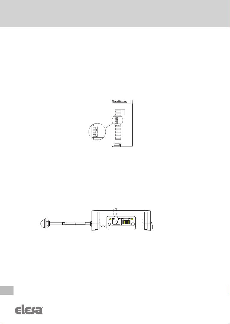
3.1. Power supply
The UC-RF control unit must be connected to a 24VDC +/-5% power supply with minimum current
capacity of 60mA. Even if the UC-RF power supply input is protected from the polarity inversion it’s
mandatory to pay attention to the polarities as printed near the power supply input on the plastic box
of the UC-RF; see the drawing below.
WARNING: The power supply line of the UC-RF has to be protected by a 100mA F type fuse.
The plug for the power supply connector is supplied with the UC-RF.
3.2. Connection to the PLC
The UC-RF must be connected to the PLC via an Ethernet RJ45 cable by using one of the two ports on the
front of it (see drawing below). Both ports are equivalent. In case two PLCs (or PLC+PC) are connected,
make sure that conflicts are avoided. For further specifications, refer to the specific communication bus
requirements.
3.3. Antenna
The antenna is supplied with the control unit. The antenna is suitable for mounting in applications
where the counterpoise will not be shielded from the antenna. The antenna must not be mounted inside
a metal cabinet; non-conductive or open metal enclosures or fixings must be used.
If the counterpoise is within a shielded enclosure it will affect the antenna performance.
The antenna must be placed in the middle of the area where the remote devices are mounted. Ideally
where it is possible to avoid any metallic shielding in between. If necessary, extension cables can be
used. RG 174/U coaxial cable (fitted with SMA male/female connectors) must be used, see on the Elesa
catalogue the available connection cables.
+ - T
+ - T

7
EN
UC-RF Control unit for DD51-E-RF DD52R-E-RF MPI-R10-RF
PLC connection, data transmission via radio frequency
Models all rights reserved in accordance with the law. Always mention the source when reproducing our drawings.
However, the best solution is to keep the antenna directly connected to the UC-RF and install it where
it’s more convenient, following the hints above.
WARNING
The range of the radio link is up to 30m in line of sight. However, in industrial environments the real
range depends on many factors - presence of walls, machine parts, metal obstacles, etc.
An accurate choice of antenna position avoids communication issues.
4. System configuration
The Elesa wireless network consists in up to 100 sub networks identified by a NetId number from 0 to 99.
Each subnet can address up to 36 remote devices, each transmitting on a different channel (Net CH).
The purpose of the subnets is to allow different machines to work near to each other with the same
device configuration (as the communication channel) without interference.
Even though it is possible to switch a UC-RF to work on different subnets (different NetID), it is strongly
recommended to dedicate one UC-RF for each subnet.
Before starting the UC-RF, please fix the parameter of the desired network by choosing NetId and Net_CH
for each remote device. Refer to the remote device user manual for their configuration and setting.
WARNINGS
fNetID 3 must be avoided because it is reserved for special uses
fPay attention to the following compatibility notes:
UC-RF
Sw
release
0F3EXXXX - 0F3AXXXX 0F051120 (from 12/2020)
Remote
device sw
release
PROFINET ETH/IP MODBUS ALL BUSES
F3.X_XX - F4.0_00
(before 06/2020)
or earlier
UC-RF and the remote devices
communicate on the same channels.
CH1 on UC-RF => CH1 on remote device.
CH2 on UC-RF => CH2 on remote device.
UC-RF communication
channels are shifted 3
positions ahead with respect
to the channels used by the
remote devices.
CH1 to CH3 on remote device:
NOT usable.
CH1on UC-RF => CH4 on
remote device.
CH2 on UC-RF => CH5 on
remote device.
CH33 to CH36 on UC-RF:
NOT usable.

8
EN
UC-RF Control unit for DD51-E-RF DD52R-E-RF MPI-R10-RF
PLC connection, data transmission via radio frequency
Models all rights reserved in accordance with the law. Always mention the source when reproducing our drawings.
UC-RF
Sw
release
0F3EXXXX - 0F3AXXXX 0F051120 (from 12/2020)
Remote
device sw
release
PROFINET ETH/IP MODBUS ALL BUSES
F5.2 (from 06/2020)
F5.3 (from 06/2020
only for MPI-R10)
NOT COMPATIBLE
The same as
for devices
with sw relea-
se F5.4 UC-RF and the remote devices
communicate on the same
channels.
CH1 on UC-RF => CH1 on
remote device.
CH2 on UC-RF => CH2 on
remote device.
F5.4 (from 12/2020)
Remote device communication channels
are shifted 3 positions ahead with respect
to the channels used by the UC-RF.
CH1 to CH3 on UC-RF Not usable.
CH4 on UC-RF => CH1 on remote device.
CH5 on UC-RF => Ch2 on remote device.
CH33 to CH36 on remote device NOT usable.
fIn systems using UC-RF with software release 0F 3E 10 18, avoid channels lower than CH 04.
fThe UC-RF will not start the network scan until it receives a valid networkID from the PLC after
power-on.
fThe parameter config code can be left =1; the UC-RF will check continuously the networkID coming
from the PLC and will change it immediately.
fUC-RF uses little endian number format. The quote/target is signed four bytes number presenting
always 0.01 mm counts.
Ex. 64 00 00 00 == 1.00 mm
1.00 mm = 100 · 0.01 mm
100 00 00 00 64 64
Hex little 00
Endian 00
00
9
EN
UC-RF Control unit for DD51-E-RF DD52R-E-RF MPI-R10-RF
PLC connection, data transmission via radio frequency
Models all rights reserved in accordance with the law. Always mention the source when reproducing our drawings.
4.1. IP address
MODBUS/TCP, Profinet and Ethernet/IP protocol identify the interfaces with an IP address.
The UC-RF is factory set with the following parameters:
IP: 192-168.1.10 static
SN Mask: 255.255.255.0
A different IP/subnet can be assigned by the PLC, or using IPConfig utility downloadable from:
https://www.anybus.com/support/file-doc-downloads/compactcom-30-series-specific/?ordercode=AB6224
It is possible to enalble the DHCP function too.
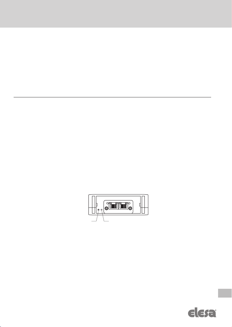
5. UC-RF status LEDs
If the connection to a channel is successful, the GREEN LED flashes.
If the connection is lost/transmission packet discarded, the RED LED flashes.
During normal operation, occasional RED LED flash can be observed. This is not an indication of failure.
If the control unit does not establish a connection to a channel after several consecutive connection
attempts, it will set the “off-air” flag for that channel.
In power, on the RED and GREEN LEDs flash for a few seconds. If the RED LED and the GREEN LED
keep flashing alternatively, please check the connection to the PLC and/or the IP address configuration.
If RED LED and GREEN LED stay ON, the UC-RF is waiting for the NEtId to be set. If RED LED stays
ON, please, contact Elesa customer service.
GREEN LED RED LED

10
EN
UC-RF Control unit for DD51-E-RF DD52R-E-RF MPI-R10-RF
PLC connection, data transmission via radio frequency
Models all rights reserved in accordance with the law. Always mention the source when reproducing our drawings.
6. BUS VARIANTS
6.1. ETHERNET/IP (CE.99225)
The module uses Class 1 (explicit) messaging.
For configuration the EDS file is available at the following link:
https://www.anybus.com/support/file-doc-downloads/compactcom-30-series-specific/?ordercode=AB6224
If the link is not reachable, please contact the Elesa customer service.
The EDS allows the PLC to recognize the UC-RF on the Ethernet/IP bus. Then it is needed to configure
all the I/O instances as described below (refer to Appendix A for status and command word definition).
Input assembly UC-RF PLC
Instance 0x64h (100 DEC), 224 bytes transfer as follows:
• offset 0x00 - channel 1 - 4 bytes actual quote, followed by 2 bytes status word
• offset 0x06 - channel 2 - 4 bytes actual quote, followed by 2 bytes status word
• ...
• offset 0xD2 - channel 36 - 4 bytes actual quote, followed by 2 bytes status word
• offset 0xD8 - current network ID
• offset 0xD9 - UC-RF status
• =0 - UC-RF waiting for networkID
• =1 - networkID initialized, scanning enabled channels in progress
• =2 to 255 reserved
• offset 0xDA - reserved
• offset 0xDB - reserved
• offset 0xDC - 4 bytes software release
Output assembly PLC UC-RF
Instance 0x96 (150 DEC), 224 bytes transfer as follows:
• offset 0x00 - channel 1 - 4 bytes target, followed by 2 bytes command word
• offset 0x06 - channel 2 - 4 bytes target, followed by 2 bytes command word
• ...
• offset 0xD2 - channel 36 - 4 bytes target, followed by 2 bytes command word
• offset 0xD8 - config byte
• offset 0xD9 - config byte content
• 0x00 - invalid config byte
• 0x01 - config byte contains network ID
• 0x02 to 0xFF reserved
• offset 0xDA - reserved
• offset 0xDB - reserved
• offset 0xDC - reserved
• offset 0xDD - reserved
• offset 0xDE - reserved
• offset 0xDF – reserved

11
EN
UC-RF Control unit for DD51-E-RF DD52R-E-RF MPI-R10-RF
PLC connection, data transmission via radio frequency
Models all rights reserved in accordance with the law. Always mention the source when reproducing our drawings.
Status LEDs
Network Status LED
LED State Description
Off No power or no IP address
Green Online, one or more connections established (CIP Class 1 or 3)
Green, flashing Online, no connection established
Red Duplicate IP address, FATAL error
Red, flashing One or more connections timed out (CIP Class 1 or 3)
Module Status LED
LED State Description
Off No power
Green Controlled by Scanner in Run state
Green, flashing Not configured, or Scanner in Idle state
Red Major fault (EXCEPTION-state, FATAL error etc.)
Red, flashing Recoverable fault(s)
Ambient conditions
LED State Description
Off No link, no activity
Green Link (100 Mbit/s) established
Green, flickering Activity (100 Mbit/s)
Yellow Link (10 Mbit/s) established
Yellow, flickering Activity (10 Mbit/s)

12
EN
UC-RF Control unit for DD51-E-RF DD52R-E-RF MPI-R10-RF
PLC connection, data transmission via radio frequency
Models all rights reserved in accordance with the law. Always mention the source when reproducing our drawings.
6.2. ProfiNET (CE.99231)
The GSD file is available at the following link:
https://www.anybus.com/support/file-doc-downloads/compactcom-30-series-specific/?ordercode=AB6221
If the link is not reachable, please contact the Elesa customer service.
The GSD file allow the PLC to recognize the UC-RF on the Profinet bus. Then it is needed to configure
56 8bits long slots as follows:
- Slot 0 to Slot 27 - output (PLC to UC)
- Slot 28 to Slot 55 - input (UC to PLC)
Each data block length is 224 bytes.
Input assembly UC-RF PLC
• offset 0x00 - channel 1 - 4 bytes actual quote, followed by 2 bytes status word
• offset 0x06 - channel 2 - 4 bytes actual quote, followed by 2 bytes status word
• ...
• offset 0xD2 - channel 36 - 4 bytes actual quote, followed by 2 bytes status word
• offset 0xD9 - UC-RF status
=0 - UC-RF waiting for networkID
=1 - networkID initialized, scanning enabled channels in progress
=2 to 255 reserved
• offset 0xDA - reserved
• offset 0xDB - reserved
• offset 0xDC - 4 bytes software release
Output assembly PLC UC-RF
• offset 0x00 - channel 1 - 4 bytes target, followed by 2 bytes command word
• offset 0x06 - channel 2 - 4 bytes target, followed by 2 bytes command word
• ...
• offset 0xD2 - channel 36 - 4 bytes target, followed by 2 bytes command word
• offset 0xD8 - config byte
• offset 0xD9 - config byte content
• 0x00 - invalid config byte
• 0x01 - config byte contains network ID
• 0x02 to 0xFF reserved
• offset 0xDA - reserved
• offset 0xDB - reserved
• offset 0xDC - reserved
• offset 0xDD - reserved
• offset 0xDE - reserved
• offset 0xDF - reserved

13
EN
UC-RF Control unit for DD51-E-RF DD52R-E-RF MPI-R10-RF
PLC connection, data transmission via radio frequency
Models all rights reserved in accordance with the law. Always mention the source when reproducing our drawings.
Status LEDs
Network Status LED
LED State Description Comments
Off Offline - No power
- No connection with IO Controller
Green Online (RUN) - Connection with IO Controller established
- IO Controller in RUN state
Green, 1 flash Online (STOP)
- Connection with IO Controller established
- IO Controller in STOP state or IO data bad
- IRT synchronization not finished
Green, blinking Blink Used by engineering tools to identify the node on
the network
Red Fatal event Major internal error (this indication is combined
with a red module status LED)
Red, 1 flash Station Name error Station Name not set
Red, 2 flashes IP address error IP address not set
Red, 3 flashes Configuration error
Expected identification differs from Real Identifica-
tion
Module Status LED
LED State Description Comments
Off Not Inizialized No power OR Module in SETUP or NW_INIT state.
Green Normal Operation Module has shifted from the NW_INIT state.
Green, 1 flash Diagnostic Event(s) Diagnostic event(s) present
Red
Exception error Device in state EXCEPTION
Fatal event Major internal error (this indication is combined
with a red network status LED)
Alternating Red/
Green Firmware update
Do NOT power off the module. During this phase
turning the module off could cause permanent
damage.
LINK/Activity LED
LED State Description Comments
Off No Link No link, no communication present
Green Link Ethernet link established, no communication present
Green, flickering Activity Ethernet link established, communication present

14
EN
UC-RF Control unit for DD51-E-RF DD52R-E-RF MPI-R10-RF
PLC connection, data transmission via radio frequency
Models all rights reserved in accordance with the law. Always mention the source when reproducing our drawings.
6.3. MODBUS/TCP (CE.99229)
The memory of the UC-RF is organised as follows (refer to Appendix A for command and status
word). Each location is 2 Bytes (16bits) long. Use function code 3 (Read/write multiple registers).
READ/WRITE - updated by the PLC
• 0x00, 0x01 - channel 1 - 4 bytes target
• 0x02, 0x03 - channel 2 - 4 bytes target
• ...
• 0x46, 0x47 - channel 36 - 4 bytes target
• 0x48 - channel 1 – command
• 0x49 – channel 2 - command
• ...
• 0x6B - channel 36 - command
• 0x6C - configuration
• LSB - config byte
• MSB - config byte content
• 0 - config byte not valid
• 1 - config byte contains network ID
• 0x02 to 0xFF reserved
• 0x6D - reserved
• 0x6E - reserved
• 0x6F - reserved
READ only - updated by the UC-RF
• 0x100, 0x101 - channel 1 - 4 bytes position
• 0x102, 0x103 - channel 2 - 4 bytes position
• ...
• 0x146, 0x147 - channel 36 - 4 bytes position
• 0x148 - channel 1 status word
• 0x149 - channel2 status word
• ...
• 0x16B - channel 36 status word
• 0x16C – Configuration status
• LSB - current network ID
• MSB - reserved
• 0x16D – reserved
• 0x16E-0x16F - 4 bytes software release
15
EN
UC-RF Control unit for DD51-E-RF DD52R-E-RF MPI-R10-RF
PLC connection, data transmission via radio frequency
Models all rights reserved in accordance with the law. Always mention the source when reproducing our drawings.
Status LEDs
Network Status LED
LED State Description
Off No power or no IP address
Green Module is in Process Active or Idle state
Green, flashing Waiting for connection
Red Duplicate IP address, or FATAL error
Red, flashing Process Active Timeout
Module Status LED
LED State Description
Off No power
Green Normal operation
Red Major fault; module is in state EXCEPTION (or FATAL event)
Red, flashing Minor fault in diagnostic object
IP conflict
LINK/ACTIVITY LEDS
LED State Description
Off No link, no activity
Green Link established, 100 Mbit/s
Green, flickering Activity, 100 Mbit/s
Yellow Link established, 10 Mbit/s
Yellow, flickering Activity, 10 Mbit/s

16
EN
UC-RF Control unit for DD51-E-RF DD52R-E-RF MPI-R10-RF
PLC connection, data transmission via radio frequency
Models all rights reserved in accordance with the law. Always mention the source when reproducing our drawings.
Appendix A – Status and command word
Status word:
bit0-bit5 - reserved.
bit6-bit9 - units. These bits indicate the actual unit of measurement of the channel. Source – remote device.
0000 - 0.01mm 0101 - 0.1 inch
0001 - 0.1mm 0110 - 1 inch
0010 - 1mm 0111 - 0.01 deg
0011 - 0.001 inch 1000 - 0.1 deg
0100 - 0.01 inch 1001 - 1 deg
bit10 - speed error: indicates rotation speed larger than programmed. The error is displayed on
the remote device. Source – remote device.
bit11 - in position: set when the target is reached within the programmed tolerance. Cleared,
when the target is outside the programmed tolerance. Source - DD52R-E-RF.
bit12 - positioning: set when the target is outside the programmed tolerance. Cleared, when the
target is reached within the programmed tolerance.
bit13 - reserved.
bit14 - battery low: set when the battery voltage is low. Source - DD52R-E-RF.
bit15 - channel off-air: If set, this bit indicates that the connection with the corresponding channel
has been lost. Possible reasons:
• DD52R-E-RF is off
• channel disabled
• Net_id not set correctly
• excessive distance to UC-RF
Source - UC-RF.
Command word:
bit0 - enable channel. Set to enable the corresponding channel. Clear to disable. When disabled,
the UC-RF will ignore it.
In case a quick connection with a single channel is needed, it is recommended to disable
momentarily the other channels - then the UC-RF will communicate only with the channel
enabled.
bit1-bit14 - reserved
bit15 - Set to indicate the target field contains a valid target. If cleared, no target will be transmitted
to the remote device. Once a valid target is set, this bit can be left on and the target is
transmitted continuously to the remote device.
17
EN
UC-RF Control unit for DD51-E-RF DD52R-E-RF MPI-R10-RF
PLC connection, data transmission via radio frequency
Models all rights reserved in accordance with the law. Always mention the source when reproducing our drawings.
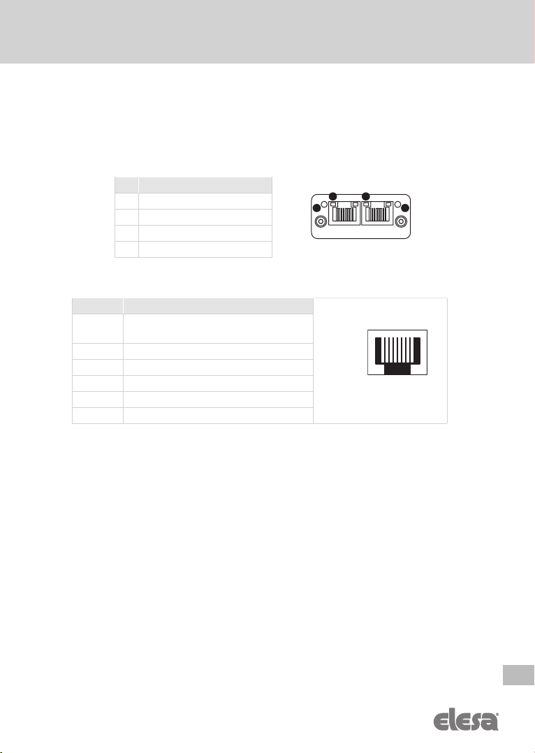
Appendix B – Bus interface connector
The ethernet interface supports 10/100Mbit, full or half duplex operation.
# Item
1 Network Status LED
2 Module Status LED
3 Link/Activity LED (port 1)
4 Link/Activity LED (port 2)
Pin n. DESCRIPTION
1, 2, 3, 4 Connected to chassis ground over
serial RC circuit
5 RD-
6 RD+
7TC-
8TC+
Housing Cable Shield
1 2
3 4
18

18
EN
UC-RF Control unit for DD51-E-RF DD52R-E-RF MPI-R10-RF
PLC connection, data transmission via radio frequency
Models all rights reserved in accordance with the law. Always mention the source when reproducing our drawings.
Appendix C – Technical data
Electrical data
Supply voltage 24 VDC ±5 %
Power consumption 50 mA
Reverse polarity Protected
Voltage transitions Protected
Frequency range 2.400-2.480GHz
Interface options
Ethernet/IP
Profinet IO
Modbus/TCP
Antenna connector SMA RP female
Power supply connector 3-way terminal block 3.81 mm pitch
Mechanical data
Mounting DIN RAIL
Weight ≈50 g
Housing material
white-gray ABS reinforced
polycarbonate,
self-extinguishing
Dimensions 79x101x35 mm
Ambient conditions
Operating temperature 0 ÷ +50°C
Storage temperature -20 ÷ +70°C
Relative humidity max. 80 %, not condensing
Environment indoor use
Altitude up to 2000 m
Ratings
protection class II
overvoltage category II
pollution degree 2

19
EN
UC-RF Control unit for DD51-E-RF DD52R-E-RF MPI-R10-RF
PLC connection, data transmission via radio frequency
Models all rights reserved in accordance with the law. Always mention the source when reproducing our drawings.
EU DECLARATION OF CONFORMITY (DOC)
WE
COMPANY NAME: Elesa S.p.a.
POSTAL ADDRESS: Via Pompei 29
POSTCODE AND CITY: 20900 Monza
TELEPHONE NUMBER: +39 039 28111
Declare that the DoC is issued under our sole responsibility and belongs to the
following product:
PRODUCT: Control unit for DD51-E-RF DD52R-E-RF MPI-R10-RF
APPARATUS MODEL: UC-RF
TRADE MARK: Elesa
The object of the Declaration described above is in conformity with the relevant
Union harmonization legislation:
2014/30/EU(EMC): Radio Equipment Directive
2011/65/UE (RoHS): Restriction of the use of certain Hazardous Substances in electrical and electronic
equipment
The following harmonized standards and technical specifications have been applied:
EN 61326-1:2013
Notified Body:
Not Involved (Annex II - Conformity Assessment Module A)
Additional information:
Software Version: 5.1 or higher
PLACE, DATE OF ISSUE: CARLO BERTANI
Monza – Italy MANAGING DIRECTOR
18/05/2020 GENERAL MANAGER

Elesa S.p.A., Monza, January 2021
The texts and examples have been written with great care. Nonetheless, mistakes can
always happen. The Company Elesa S.p.A. can neither be held legally responsible nor
liable for lacking or incorrect information and the ensuing consequences. The Company
Elesa S.p.A. reserves the right to alter or improve the electronic position indicators or
parts of them and/or the enclosed brochures without prior notice.
© COPYRIGHT ELESA 2021
Art. Nr. ZDOIU-UC-RF-EN-R0
ELESA S.p.A.
Via Pompei, 29
20900 Monza (MB) Italy
phone +39 039 28111
www.elesa.com
This manual suits for next models
1
Table of contents
Popular Control Unit manuals by other brands


CSW
CSW RECTORSEAL EZ TRAP EZT180 Product data sheet

Kantech
Kantech Ethernet Four-Door Controller KT-400 quick start guide

Navim Group Company
Navim Group Company EsiWelma Sensigas UCE1 installation instructions

APS
APS EPM205-MRS Technical reference

Enclustra
Enclustra Mars ZX3 user manual

Runxin
Runxin 55504 user manual


