manuals.online logo
Brands
  1. Home
  2. •
  3. Brands
  4. •
  5. Kantech
  6. •
  7. Control Unit
  8. •
  9. Kantech Ethernet Four-Door Controller KT-400 User manual

Kantech Ethernet Four-Door Controller KT-400 User manual

Other manuals for Ethernet Four-Door Controller KT-400

1

This manual suits for next models

1

Other Kantech Control Unit manuals

Kantech KT-MOD-OUT16 User manual

Kantech

Kantech KT-MOD-OUT16 User manual

Kantech KT-PC4216 User manual

Kantech

Kantech KT-PC4216 User manual

Kantech KT-MOD-REL8 User manual

Kantech

Kantech KT-MOD-REL8 User manual

Popular Control Unit manuals by other brands

Seitz 14A80 user manual

Seitz

Seitz 14A80 user manual

Wilo RS485 Installation and operating instructions

Wilo

Wilo RS485 Installation and operating instructions

Becker CentralControl CC41 Commissioning Instruction

Becker

Becker CentralControl CC41 Commissioning Instruction

SICK CDB650 operating instructions

SICK

SICK CDB650 operating instructions

Panduit NetKey NKP5E88M Series installation instructions

Panduit

Panduit NetKey NKP5E88M Series installation instructions

MX Options Concentric Petite Fitting instructions

MX

MX Options Concentric Petite Fitting instructions

Clean Water Systems Fleck 2510 Installation & start?up guide

Clean Water Systems

Clean Water Systems Fleck 2510 Installation & start?up guide

Fairchild FSB44104A user guide

Fairchild

Fairchild FSB44104A user guide

LEGRAND Wattstopper LMIN-104 installation instructions

LEGRAND

LEGRAND Wattstopper LMIN-104 installation instructions

PMK ATT10BNCS instruction manual

PMK

PMK ATT10BNCS instruction manual

Tektronix TDS3FFT user manual

Tektronix

Tektronix TDS3FFT user manual

Woodward easYgen Technical manual

Woodward

Woodward easYgen Technical manual

Balluff BNI EIP-502-105-R015 user guide

Balluff

Balluff BNI EIP-502-105-R015 user guide

NXP Semiconductors TWR-LS1021A Getting started

NXP Semiconductors

NXP Semiconductors TWR-LS1021A Getting started

Advantech PCM-3117 Startup manual

Advantech

Advantech PCM-3117 Startup manual

Danfoss MCO 101 manual

Danfoss

Danfoss MCO 101 manual

Moons' Lin Engineering R701P user manual

Moons'

Moons' Lin Engineering R701P user manual

Aventics RV1 operating instructions

Aventics

Aventics RV1 operating instructions

manuals.online logo
manuals.online logoBrands
  • About & Mission
  • Contact us
  • Privacy Policy
  • Terms and Conditions

Copyright 2025 Manuals.Online. All Rights Reserved.

Tel.: 1 (450) 444 2030 •Toll Free: 1-888-222-1560 •Fax: 1 (450) 444 2029 •Internet: www.kantech.com DN1786-1112
Copyright © 2008 Tyco International Ltd. and its Respective Companies. All Rights Reserved. •Specifications may change without notice.
Kantech and the Kantech logo are trademarks of Tyco International Ltd. and its Respective Companies.
KT-MOD-REL8
KT-400 Expansion Module 8-Relay with SPI Cable Install Sheet
1. Introduction
The KT-MOD-REL8 is an 8-relay outputs expansion module used
as general relays or elevator control outputs.
The module supports daisy chaining which can add up to 32 KT-
MOD-REL8 modules for a total of 256 external relays per KT-400
controller. You can mix relays and outputs in the same SPI group,
up to 256 outputs.
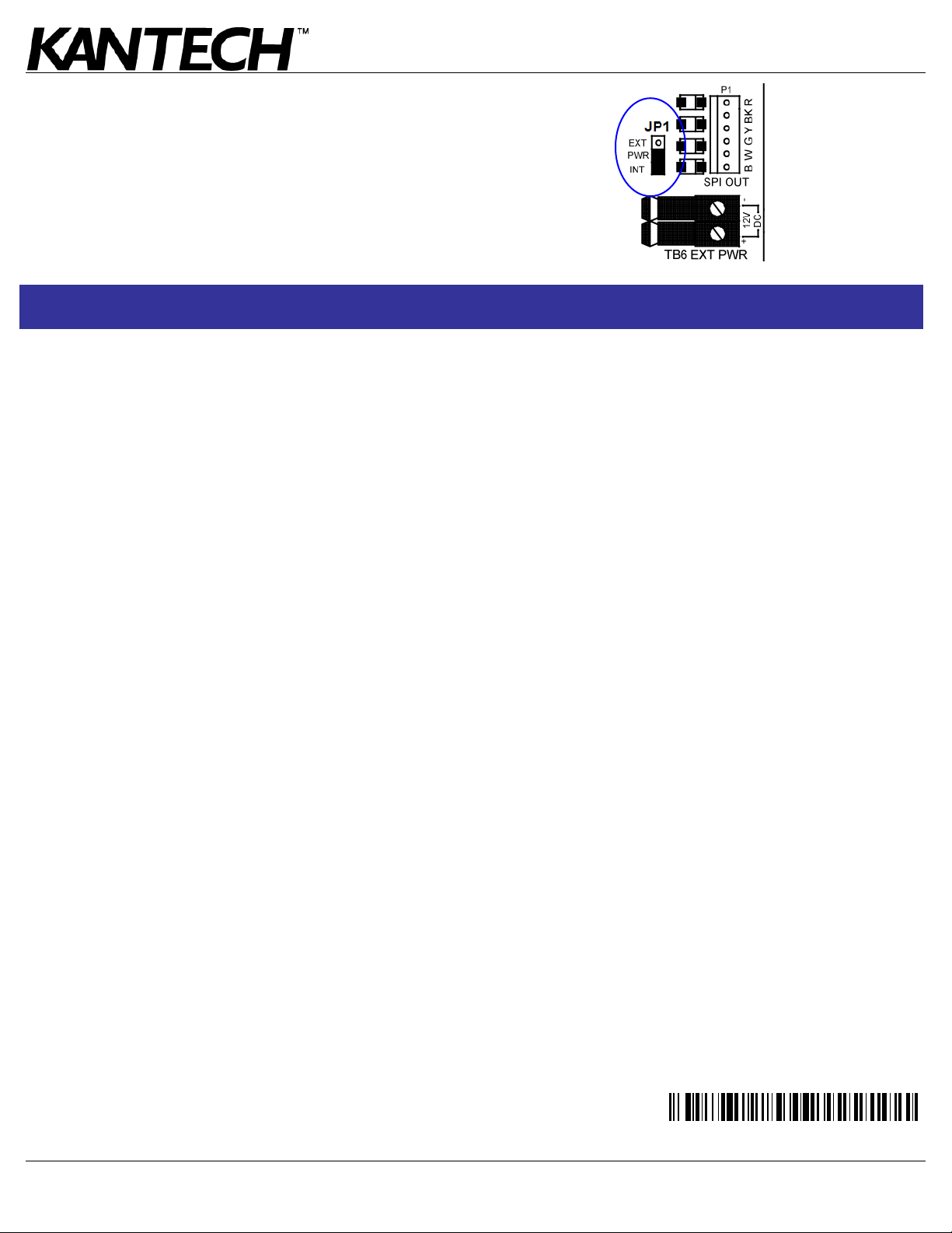
Note 1: The KT-400 SPI port maximum current draw, when the
12V AUX terminals are not used, is 500 mA.
Note 2: External power supply (12 VDC, 2 Amps) is required
when the total current draw exceeds 500mA on the SPI Port.
Note 3: There are already 4 relays available on the KT-400.
Make sure to check the relays number assignments to prevent
redundancy unless it has been planned on purpose.
2. Specifications
•Maximum Current Draw: up to 330 mA per module
•Each relay supports the 2 conditions, NO (Normally Open)
and NC (Normally Closed), the C (Common) terminal is +12
VDC
•Each relay has its own LED to indicate status, ON for active
•Eight (8) programmable relay contacts rated 30 VDC, 3 A
•Can be used for elevator control
•Can be mixed with output module KT-MOD-OUT16 in the
same group
•Operating Temperature: -10C to +55C
•Maximum Humidity: 93% (non condensing)
•IP Class 3X, IK Rating 04 (when mounted in Kantech
cabinet)
3. Installing the KT-MOD-REL8 Module
3.1. Unpacking
The KT-MOD-REL8 package includes the following parts:
•One (1) module - 14 cm x 8 cm (5.7 in x 3.25 in)
•One (1) SPI cable with 1 SPI connector 41 cm (16 in)
•Four (4) plastic standoffs
•Two (2) installation sheets, English and French
3.2. Mounting
The KT-MOD-REL8 can be installed inside a compatible cabinet
(KT-MOD-CAB or KT-400) or mounted in a dry and secure
location at less than 1 m (3 ft) from the KT-400.
Perform the following steps to mount the unit:
1. Press the four (4) plastic standoffs through the mounting
holes of the cabinet,
2. Secure the cabinet to the wall in the desired location. Use
appropriate wall anchors when securing the cabinet to
drywall, plaster, concrete, brick or other surfaces,
3. Press the module into the plastic standoffs to secure the
module to the cabinet.
3.3. Installation and Wiring
Before beginning to wire the unit, ensure that all power (AC
transformer and battery) is disconnected from the KT-400.
Perform the following steps to complete wiring:
1. Connect the 6-pin SPI connector to:
•
the KT-400 SPI port, or
•
the SPI OUT of the previous output module (KT-MOD-
REL8 and KT-MOD-OUT16 only), or
•
the SPI EXP of the 1st input module KT-MOD-INP16
connected to the KT-400 SPI port.
2. Connect the six SPI wires (blue (BLU), white (WHT), green
(GRN), yellow (YEL), black (BLK) and red (RED)) to the SPI
IN (TB1) terminals.
3. Connect the 6-pin SPI connector from the SPI OUT to the
next output module (KT-MOD-REL8 and KT-MOD-OUT16
only).
4. Complete all output wiring.
Tel.: 1 (450) 444 2030 •Toll Free: 1-888-222-1560 •Fax: 1 (450) 444 2029 •Internet: www.kantech.com DN1786-1112
Copyright © 2008 Tyco International Ltd. and its Respective Companies. All Rights Reserved. •Specifications may change without notice.
Kantech and the Kantech logo are trademarks of Tyco International Ltd. and its Respective Companies.
KT-MOD-REL8
KT-400 Expansion Module 8-Relay with SPI Cable Install Sheet
3.4. Check the power jumper JP1 position. Put it on EXT if you
need external power or INT if no external power is required.
3.5. Applying Power
After all wiring is completed, connect the 16 VAC to the KT-400.
Connect the battery leads to the battery, and then apply power to
the AC transformer.
Note: Do not connect power until all wiring is complete.
This module provides access point control (5) as per EN50133-1.
Terminal Connections
Module no.:_______________________________________________________________________________________
Date of installation: ________________________________________________________________________________
KT-400 Name: _____________________________________________________________________________________
KT-400 SITE NAME: ________________________________________________________________________________
KT-400 Serial Number:______________________________________________________________________________
AUX: ____________________________________________________________________________________________
SPI BUS (FROM): __________________________________________________________________________________
SPI BUS (TO): _____________________________________________________________________________________

NO RLY1: _____________________________________

NO RLY5: ____________________________________

NC

NC

NO RLY2: _____________________________________

NO RLY6: ____________________________________

NC

NC

NO RLY3: _____________________________________

NO RLY7: ____________________________________

NC

NC

NO RLY4: _____________________________________

NO RLY8: ____________________________________

NC

NC
FCC COMPLIANCE STATEMENT
CAUTION: Changes or modifications not expressly approved by Kantech could void your authority to use this equipment.
This equipment generates and uses radio frequency energy and if not installed and used properly, in strict accordance with the manufacturer’s instructions, may cause interference to radio and
television reception. It has been type tested and found to comply with the limits for Class B device in accordance with the specifications in Subpart “B” of Part 15 of FCC Rules, which are
designed to provide reasonable protection against such interference in any residential installation. However, there is no guarantee that interference will not occur in a particular installation. If this
equipment does cause interference to television or radio reception, which can be determined by turning the equipment off and on, the user is encouraged to try to correct the interference by one
or more of the following measures:
• Re-orient the receiving antenna
• Relocate the alarm control with respect to the receiver
• Move the alarm control away from the receiver
• Connect the alarm control into a different outlet so that alarm control and receiver are on different circuits.
If necessary, the user should consult the dealer or an experienced radio/television technician for additional suggestions. The user may find the following booklet prepared by the FCC helpful:
“How to Identify and Resolve Radio/Television Interference Problems”. This booklet is available from the U.S. Government Printing Office, Washington, D.C. 20402, Stock # 004-000-00345-4.
This device complies with Part 15 of the FCC rules. Operation is subject to the following two conditions: (1) this device may not cause harmful interference, and (2) this device must
accept any interference received including interference that may cause undesired operation.
This class B digital apparatus complies with Canadian ICES-003.
The KT-400 is also compliant with EN55022: Class B.
D29008294R001