GENERAL
The UCE1 control unit can be used to connect one detector (model
URx13 or URx20/21..) to create gas detection systems in
environments such as boiler rooms, workshops, warehouses,
laboratories etc.; the incorporated alarm relay can be used to
control a solenoid valve or an accessory device (siren, flashing
light, extractor, etc.). The installation of a gas or carbon monoxide
detection system does not constitute a release from compliance
with all regulations for the installation and use of gas devices and
with the relative safety standards and legal provisions in force for
this kind of system. Installation, periodic inspections and
maintenance of devices and systems must be carried out by
qualified service technicians.
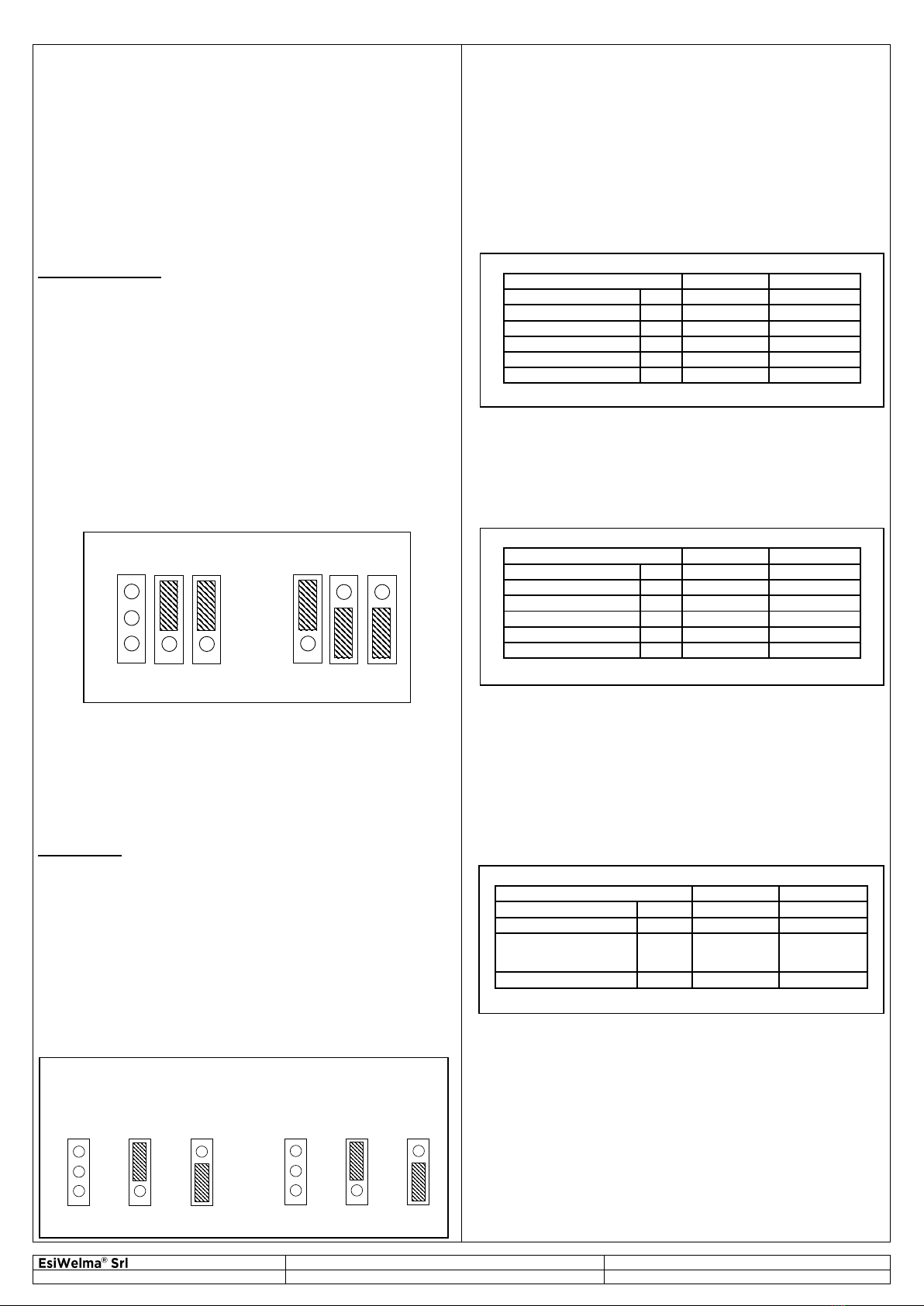
TECHNICAL SPECIFICATIONS
UCE1 control unit (data URx20/21.. detectors in brackets)
Power supply: 12 Vac/dc 10%
Consumption: about 160mA (320mA) with the detector only
460mA (620mA) with detector and failure
output
Connections: two terminals of 2.5 mm2
Protection: Power input fuse 1A 5x20mm
Inputs: one, for UGR13, URP13, URO13 detectors, or
URx20/21.. detectors (different types of gas)
Detector connection: three terminals of 2.5 mm2:
C (-12...24V); S (+4…20mA); A (+12...24V)
Max cable run length: 50 m
Diameter of the 3 wires: 1.5 mm2
Alarm output: 1 relay with one contact SPDT 8A 250Vac
Failure output: one open collector 12Vdc / 300mA max
Output connections: three terminals of 2.5 mm2for C-NC-NO relay
two terminals of 2.5 mm2for open collector
Visual alarms: 1 green LED: power on
1 yellow LED: failure
1 red LED: gas alarm
Audible alarms: 1 buzzer noise level > 60db at 1m
“Reset/Test” button: 1 for alarm Reset and detector Test
Enclosure: RAL7035 grey, self-extinguishing plastic house
Dimensions and weight: 105x90x58 mm (6 modules to standard DIN
43880), 185 g
Mounting: Back panel Omega DIN rail (EN 50022)
Protection rating: IP20; IP40 when correctly installed in
electric panel
Room temperature: -20…+55°C
Humidity 90% RH (non condensing)
Conformity 0474 / xxxx (manufacturing year)
CERTIFICATE n. MED327120CS
MED Directive / Standards MED 2014/90/EU / IEC 60092-504
EMC Directive / Standards EMC 2014/30/EU / EN50270 / EN 61326-1
LVD Directive / Standards LV 2014/35/EU / EN60730-1
Product Standard EN60079-29-1
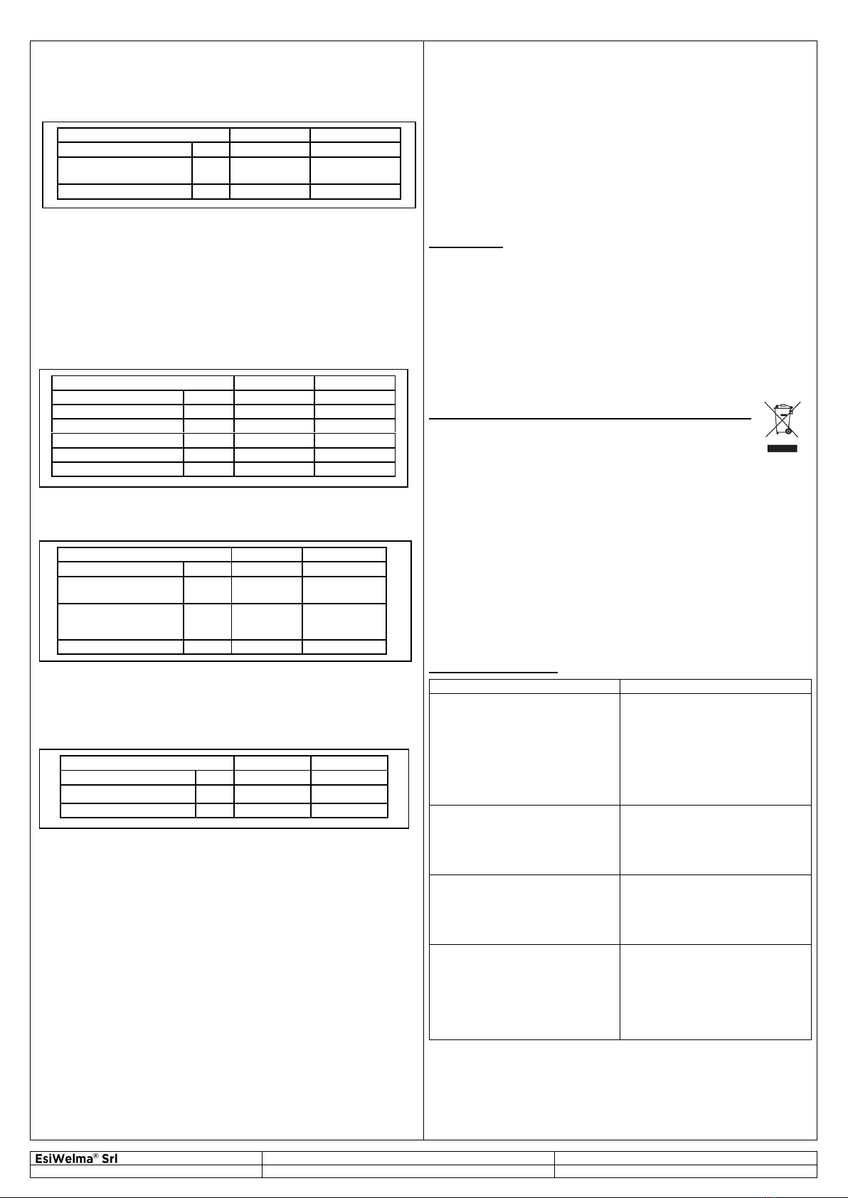
URx13 (URx20/21..) detectors
Power supply: from the UCE1 control unit
Consumption: 40 mA (200mA)
Connections: three terminals of 2.5 mm2:
C (-12...24V); S (+4…20mA); A (+12...24V)
URx13 models: Methane Gas URG13
LPG URP13
Carbon Monoxide URO13
URx20/21.. models: Various gases, see dedicated data sheet
Calibration: URG13: 10% LEL of Methane
URP13: 12% LEL of LPG
URO13: 200ppm of CO
(URx20/21..: 20% LEL, 100ppm CO)
Enclosure: self-extinguishing plastic
Dimensions and weight: 66x90x45 mm (depending on model), 65 g
Mounting: wall-mounted using plastic screws and anchors
Protection: IP44 (IP44, IP55 or IP65 depending on model)
Room temperature: 0…+50°C (-20…+50°C till -40…+70°C)
Humidity: 90% RH (non condensing)
LVD Directives/Standards Not applicable
EMC Directives/Standards EMC 2014/30/EU / EN50270
Other features of URx20/21.. detectors
See their technical features on dedicated data sheet.
INSTALLATION
MOUNTING
Ensure correct environmental conditions (See Technical
Specifications).
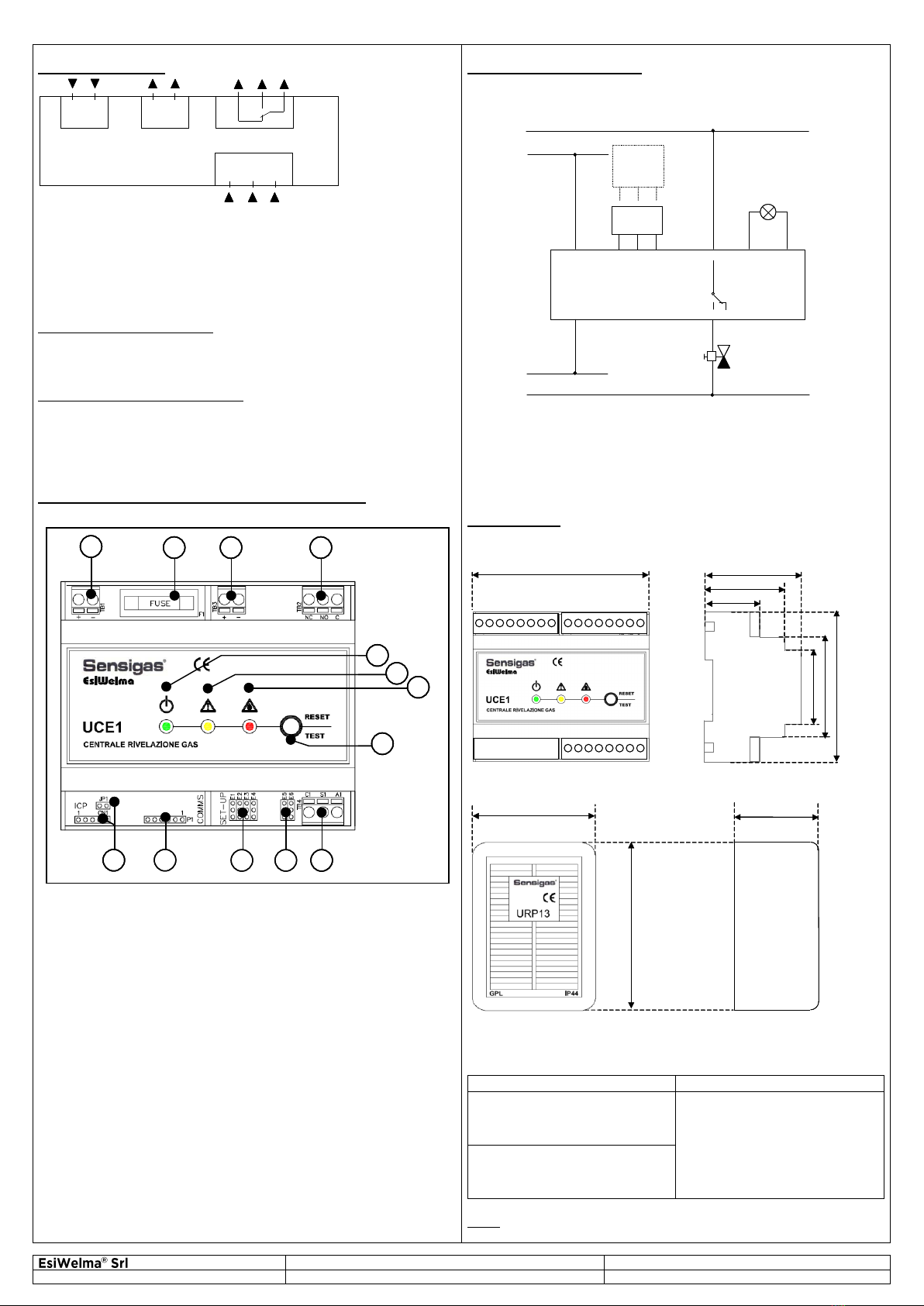
UCE1 control unit
To guarantee the correct protection rating for the device it must
be installed in an electric panel manufactured according to the
laws in force for workplaces and that can also house the power
supply system. Mount the control unit on a rail (to DIN EN
50022), using accessories for standard electric panels. It can be
installed on a mounting plate or in DIN rail modules.
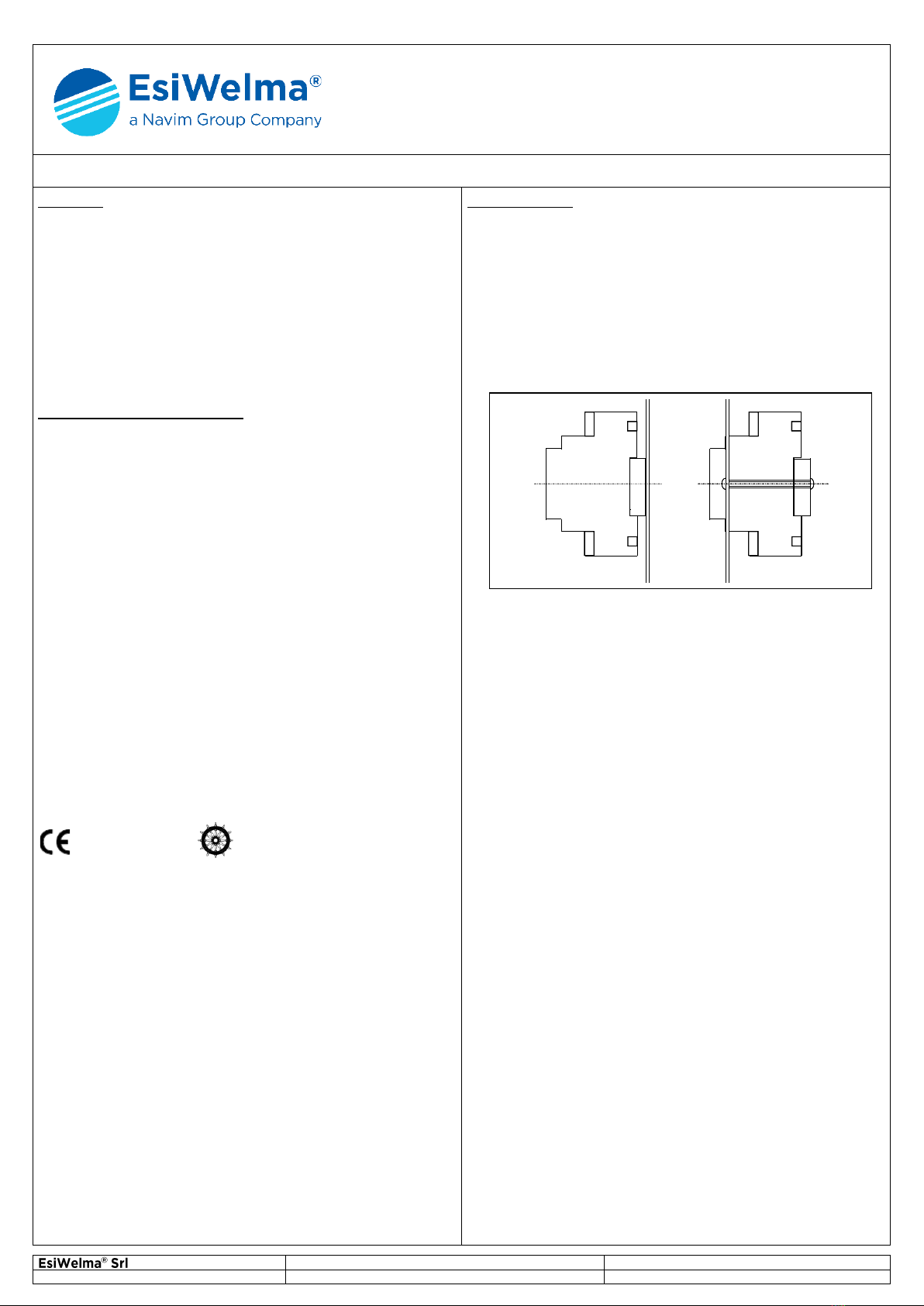
URx13 (URx20SW) detectors
To be used for wall-mounting (vertical), attached by plastic
screws and anchors. To install, insert a screwdriver in the recess
at the bottom of the enclosure to open it; avoid damage to the
sensor and do not touch the calibration devices. The detectors
must be correctly positioned for the system to operate properly.
For this purpose, the control units must be installed:
-in zones with constant natural air circulation
-in zones free of dust and dirt that could clog up the sensor and
make it ineffective
-never near running water, exhaust vents, windows, openings
etc.
-at a suitable distance from the gas-fuelled equipment to avoid
the system taking inappropriate action due to possible
functional loss.
The positioning also depends on the type of gas that is to be
detected, in particular:
-URG13: Methane gas - high, about 20-30 cm from ceiling
-URP13: LPG - low, about 20-30 cm from floor
-URO13: CO - about 1.5 m from floor
For new plants, the detector must be installed at the last possible
moment so that typical worksite activities (particularly welding,
painting, sealing etc.), do not damage the actual detector
(particularly the sensing element).
URx20/21.. detectors
See installation instructions on dedicated data sheet.
ELECTRICAL CONNECTIONS
Normal electric cables can be used. Still, if detectors are to be
installed in environments with high exposure to EMI, it is
advisable to use shielded cables. The detection system must
always be operating, so power switches or other devices that
could inadvertently make the detector inoperative must not be
used. Do not touch the sensing element and the electronic circuits
for any reason whatsoever. Tampering of any kind may cause the
system to operate incorrectly.
Ensure compliance with all current electric standards.