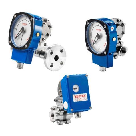
Eletta EMF Series User manual

EMFA2E21
Manual EMF Series
Electromagnetic Flow Meters

2
Content Page
1. General Information 3
1.1. Product Description 3
1.2. Unpacking and Inspection 3
1.3. Transport and Handling 3
2.
Technical Data 4
2.1. Measuring system 4
2.2. Design 4
2.3. Measuring Accuracy 4
2.4. Operating conditions 5
2.5. Installation conditions 5
2.6. Materials 5
3. Models and Selection 6
4. Cautions for Installation 7
4.1 Mounting Positions 7
4.2. Required Lengths of the Straight Runs 8
4.3 Grounding 8
4.4 Connections 9
5. Electrical Wiring 10
5.
1. Safety Instructions 10
5.2 Terminal Configuration Diagram 10
5.2.1 Compact Converter Terminal Configuration 10
5.2.2. Remote Converter Terminal Configuration 11
6. Programming and Setup 11
6.1. Description of Outputs 11
6.1.1. Digital Frequency Output 11
6.1.2. Digital Pulse Output 12
6.1.3. Alarm Output 12
6.2. Output Connection 12
6.2.1. Current Output 12
6.2.2. Digital Voltage Output 13
6.2.3. Digital Voltage Output to Photoelectric Coupling 13
6.2.4. Digital Output to Relay 13
7. Operation and Setup 14
7.1. Display and Keys 14
7.1.1. Compact Version 14
7.1.2 Remote Type 14
7.2. Function Selection Menu 15
7.3. Parameters Setting 15
7.4. Parameter Function Table 17
8. Alarm Information 19
9. Troubleshooting 19
10. Contact 20

3
1. General Information
This manual will assist you in installing, using and maintaining the Eletta flow meter. lt is your
responsibility to make sure that all operators have access to adequate instructions about safe
operating and maintenance procedure.
For your safety, review the major warnings and cautions below before using your equipment.
Use only fluids that are compatible with the housing material and wetted components of your meter.
When measuring flammable liquids, observe precautions against fire or explosion.
When handling hazardous liquids, always follow the fluids manufacturer's safety precautions.
When working in hazardous environments, always apply appropriate safety precautions.
During meter removal, fluids may spill. Follow the fluids manufacturer's safety precautions for clean up
of minor spills.
When tightening the meter, use a wrench only on the wrench flats.
For best results, calibrate the meter at least 1 time per year.
1.1. Product Description
Electromagnetic flow meters are intended for fluid measurement in most industries including water,
wastewater, food and beverage, pharmaceutical and chemical.
The Eletta electromagnetic flow meter consists of two main components:
1) The Detector, which includes the flow tube, isolating liner and measuring electrodes, and
2) The Converter, which is the electronic device responsible for signal processing, flow calculation,
display and output signals.
The materials of construction of the wetted parts (liner and electrodes) should be appropriate for the
specifications on the intended use. Review of the compatibilities of the specifications is
recommended.
Eletta's electromagnetic flow meters are factory tested and calibrated. A calibration certificate is
included in the shipment of each meter.
1.2. Unpacking and Inspection
Upon receipt, check your meter for visible damage. The meter is a precision measuring instrument and has
to be handled carefully. Remove the protective plugs and caps for a thorough inspection, If any items are
damaged or missing, contact us.
Make sure the flow meter model meets your specific needs. For your future reference, it might be useful to
record this information on nameplate in the manual in case it becomes unreadable on the meter.
1.3.Transport and Handling
Do not lift the detector from the Converter housing, the junction box or the connecting cable. The
use of lifting lugs for larger sizes is recommended. Very large meter sizes are packed and crated
with the meter laying on its side for shipping safety and stability reasons. In order to lift the meter in
vertical position, it's recommended to use a sling rigged method as shown below.

4
Warning: NEVER insert the forklift`s fork,
chains, wire slings or any other sharp object inside the flow tube for lifting or handling purpose.
This could permanently damage the isolating liner and could render the meter inoperable.
lf using a forklift, do not lift the detector on its body between the flanges. The housing could be
accidentally dented and permanent damage could be caused to the internal coil assemblies.
2. Technical Data
2.1. Measuring system
Measuring principle
Faraday's law
Application range
Electrically conductive fluids
Primary measured value
Flow velocity
Secondary measured value
Volume flow
2.2. Design
Fully welded maintenance-free sensor
Flange version with full bore flow tube
Large diameter range from DN25 -DN3000 with rugged liners approved for drinking water
Industry specific insertion lengths
Modular construction: The measurement system consists of a flow sensor and a signal converter.
lt is available as compact and as remote version.
Compact version power supply: 110-VAC Power, 18-36V DC Power, Battery Power
Remote version power supply: 110-240VAC Power, 18-36VDC Power, Battery Power
Measurement range: -12 ... +12 m/s
2.3. Measuring Accuracy

5
2.4. Operating conditions
Process temperature Hard rubber liner:
-5 ...
+60°C
Polypropylene liner: -5 ... +90°C
PTFE liner:
-5 ...
+120°C
Ambient temperature -20 ... +60°C
(Protect electronics against self-heating with ambient temperatures >55°C)
Storage ternperature -20 ... +70°C
Pressure PN16
Pressure drop negligible
Fluid Physical condition: conductive liquids
Electrical conductivity 5 μSiemens/cm
Permissible gas content (volume) <=5%
Permissible solid content (volume) <=70%
2.5. Installation conditions
Take care that the flow sensor is always fully filled.
For detailed information see chapter 4. "Cautions for Installation".
Flow direction forward and reverse. Arrow on flow sensor indicates positive flow direction.
Inlet run 5DN
Outlet run 2DN
2.6. Materials (also see Chapter 3, Models and Selection)
Sensor housing Sheet steel, Polyurethane coated
Measuring tube
Austenitic stainless steel
Flanges Carbon steel; Polyurethane coated
Option: stainless steel
Liner DN10-DN40: F46
DN50-DN300: PTFE or Hard Rubber
>DN300: Hard Rubber
Connection box (only remote versions): polyurethane coated die-cast aluminium
Measuring electrodes: Standard: Stainless steel 316L
Option: Hastelloy C, Titanium, Tantalum
Grounding rings Standard: Stainless steel
Grounding electrodes (option) Same material as measuring electrodes
Measurable Flow Range
Generally, the Flow Meter is calibrated between 0.3-6m/s if there is not special request

6
3. Models and Selection

7
4. Cautions for Installation
4.1 Mounting Positions
Pipes must be fully filled with liquids. It is essential that pipes remain fully filled at all times,
otherwise flow rate indications may affected, and measurement errors may be caused.
Avoid Air Bubbles. If air bubbles enter a measurement pipe, flow rate indications may be affected
and measurement errors may be caused.
If the electrodes are vertical to the ground, air bubbles near the top or precipitates at the bottom may
cause measurement errors.. Ensure that the terminal box is mounted above the piping to prevent
water from entering them.
Avoid all pipe locations where the medium is pulsating, such as in the outlet side of piston or
diaphragm pumps.
Avoid locations near equipment producing electrical interference such as electric motors,
transformers, variable frequency etc.
Install the meter with enough room for future access for maintenance purposes.
The magnetic meter isolating liner, whether if it is PTFE or rubber, ls not intended to be used as
gasket material. Standard gaskets (not provided) should be installed to ensure a proper hydraulic
sealing. When installing the gaskets, make sure they are properly centered to avoid flow restriction
or turbulence. Do not use graphite or any electrically conductive sealing compounds to hold the
gaskets in place during installation. This could affect the reading accuracy of the measuring signal.
Take precautions against direct sunshine and rain when the meter is installed outside.

8
4.2. Required Lengths of the Straight Runs
For optimum accuracy, it is required to provide sufficient inlet and outlet straight pipe runs. An equivalent
to 5 diameters of straight pipe is required on the inlet side, and 2 diameters on the outlet side. There are
no special requirements for standard concentric pipe reducers. See diagram
1
for required straight runs.
When the meter contains removable cover plates, leave the cover plate installed unless accessory
modules specify removal. Don't remove the cover plates when the meter is powered, or electrical shock
and explosion hazard can be caused.
4.3 Grounding
In this section, the term “grounding” will be defined as the arrangement of process wetted metal
materials (piping, grounding rings, grounding electrodes), cabling (grounding straps, grounding wires),
and connections to stable references (often, but not always earth ground) required to achieve
satisfactory operation of a magnetic flowmeter. As such, it applies to instrumentation aspect of
grounding, rather than to "safety grounding”.
Proper installation and grounding of the flowmeter is important for accurate, reliable measurement
performance. Stray AC or DC currents, through the fluid or instrument can produce noise signals that
may in turn interfere with the relatively low flow signals generated in today's modern pulsed DC
magmeters.
Manufacturers provide a variety of elements (ground straps, ground electrodes, ground rings) and
directions for the standard grounding of the magmeter.
Applications exist in which the user cannot, or should not make use of the traditional grounding
connection to adjacent piping or to earth ground. These flow measurement applications are frequently
encountered in electrolytic processes. In this case, the fluid passing through the magmeter flow tube
may be at a potential significantly higher or lower than earth ground, and a connection to earth ground
may be detrimental to the performance and even the reliability of the magmeter. These applications are
typically compounded by the use of non-conductive or lined pipe and may feature acid or caustic flows
which may necessitate the use of expensive wetted electrodes and grounding materials such as
titanium, platinum, or tantalum.

9
4.4 Connections
Use a gasket between the meter flange and mating flange Determine the material of the gasket based
on the operating conditions and type of fluid.
Do not overtighten the flange bolts. This may cause the gaskets to be compressed into the flow stream
and may decrease the accuracy of the meter.
Installation dimensions:

10
POUT Frequency (Pulse) Output for Bi-Directional Flow
ALM1 Alarm Upper Limit
ALM2 Alarm Lower Limit
COMM Frequency, Pulse and Current Common (GND)
COMM Frequency, Pulse and Current Common (GND)
IOUT Current Output of Flow Rate
IVIN 24VDC Power Supply for 2-Wire 4-20mA Output
TRX+ + Communication RS485 (+)
TRX- - Communication RS485 (-)
LN+ L: Live Wire of 110-240VAC +: 24VDC +
LN+ L: Naught Wire of 110-240VAC -: 24VDC -
5. Electrical Wiring
5.1. Safety Instructions
All work on electrical connections may only
carried out when the power disconnected.
Observe the national regulations for electrical installations!
Observe the local health and safety regulations. Any work done on the electrical components of the
measuring device may only be carried out by properly trained specialists.
Look at the device`s product plate to ensure that the device is delivered according to your order.
Check for the correct supply voltage shown on the nameplate.
Use suitable cable entries for the various electrical cables.
The sensor and the converter are configured together in the factory. Therefore, please connect the devices
in pairs. Ensure that the sensor constant GK are identically set.
5.2 Terminal Configuration Diagram
5.2.1 Compact Converter Terminal Configuration

11
Pulse Output POUT Frequency Pulse Output for Bi-Directional Flow
PCOM Pulse Output Ground
Alarm Output ALMH Alarm Upper Limit
ACOM Alarm Output Ground
RS485 (optional) TRX+ Communication RS485+
TRX- Communication RS485-
Analog Current Output
VDIN 24VDC Power Supply for 2-Wire 4-20mA Output
IOUT Analog Current Output
ICOM Analog Current Output Ground
Power Supply L/+ L: Live Wire 110-240VAC; +:24VDC +
N/- N: Naught Wire 110-240VAC; -24VDC -
Signal from Sensor SIG1 Signal 1
SGND Signal Ground
SIG2 Signal 2
TCOM Reserved
EXT+ Exciting Current +
EXT- Exciting Current -
DS1 Shielded Exciting 1
MTSR Reserved
DS2 Shielded Exciting 2
5.2.2. Remote Converter Terminal Configuration
6. Programming and Setup
Magnetic flow meters are designed exclusively to measure the flow and conductivity of electrically
conductive, liquid media.
Your flow meter is supplied ready for operation. The factory settings for the operation data have been
made in accordance with your order specifications.
6.1. Description of Outputs
6.1.1. Digital Frequency Output

12
6.1.2. Digital Pulse Output
6.1.3. Alarm Output
6.2. Output Connection
6.2.1. Current Output

13
6.2.2. Digital Voltage Output
6.2.3. Digital Voltage Output to Photoelectric Coupling
Generally, photoelectrical coupling current is 10mA. When E/R=10mA, E= 5-24VDC
6.2.4. Digital Output to Relay
Generally, E (Vollage) of lhe relay is 12V or 24V; D is exlended diode, rnost middle relays have this
diode inside. lf not, user should connect one outside.

14
7.0 Operation and Setup
7.1. Display and Keys
7.1.1. Compact Version
7.1.2. Remote Type

15
7.2. Function Selection Menu
7.3. Parameters Setting
Press > and Enter, this leads to functions election menu and the first menu is “Parameters Set”, press
Enter to confirm this menu. Enter the password and press > + Enter.
There are 54 menus totally in “Parameters Set” and users can access and modify these menus depending
on the input password grade. See table for more information on the password grade:

16
Menu Parameter Name Setting Method Grades Range
M1 Language Select Parameter 2 English
M2 Comm Address Input Value 2 0-99
M3 Baud Rate Select Parameter 2 600-14400
M4 SNSR Size Select Parameter 2 3-3000
M5 Flow Unit Select Parameter 2 l/h, l/min, l/s, m³/h, m³/min, m³/s
M6 Flow Range Input Value 2 0-99999
M7 Fleo RSPNS Select Parameter 2 1-50
M8 Flow Direct Select Parameter 2 Rlus/Reverse
M9 Flow Zero Input Value 2 0- +/-9999
M10 Flow Cutoff Input Value 2 0-599,99%
M11 Cutoff Ena Select Parameter 2 Enable/Disable
M12 Total Unit Select Parameter 2 0,001m³-1m³, 0,001l-1l
M13 SegmaN Ena Select Parameter 2 Enable/Disable
M14 Analog Type Select Parameter 2 0-10mA/4-20mA
M15 Pulse Type Select Parameter 2 Frequen/Pulse
M16 Pulse Fact Select Parameter 2 0,001m³-1m³, 0,001l-1l
M17 Freque Max Select Parameter 2 1-5999 Hz
M18 MTSNSR Ena Select Parameter 2 Enable/Disable
M19 MTSNSR Trip Input Value 2 59999%
M20 Alm Hi Ena Select Parameter 2 Enable/Disable
M21 Alm Hi Val Input Value 2 0-599,99%
M22 Alm Lo Ena Select Parameter 2 Enable/Disable
M23 Alm Lo Val Input Value 2 0-599,99%
M24 Sys Alm Ena Select Parameter 2 Enable/Disable
M25 Clr Sum Key Input Value 3 0-99999
M26 Snsr Code 1 User Set 4 Finished Y N
M27 Snsr Code 2 User Set 4 Product Number
M28 Field Type Select Parameter 4 Type 1,2,3
M29 Sensor Fact Input Value 4 0-5,9999
M30 Line Crc Ena Select Parameter 4 Enable/Disable
M31 Linearity CRC1 User Set 4 Set Velocity
M32 Linearity Fact 1 User Set 4 0-1,9999
M33 Linearity CRC2 User Set 4 Set Velocity
M34 Linearity Fact 2 User Set 4 0-1,9999
M35 Linearity CRC3 User Set 4 Set Velocity
M36 Linearity Fact 3 User Set 4 0-1,9999
M37 Linearity CRC4 User Set 4 Set Velocity
M38 Linearity Fact 4 User Set 4 0-1,9999
M39 Fwd Total L Correctable 5 00000-99999
M40 Fwd Total Hi Correctable 5 00000-9999
M41 Rev Total Lo Correctable 5 00000-99999
M42 Rev Total Hi Correctable 5 00000-9999
M43 PlsntLmtEna Select Parameter 5 Enable/Disable
M44 PlsntLmtVal Select Parameter 5 0,01-0,800ms
M45 Plstn Delay Select Parameter 5 400-2500ms
M46 Password 1 User Correct 5 00000-99999
M47 Password 2 User Correct 5 00000-99999
M48 Password 3 User Correct 5 00000-99999
M49 Password 4 User Correct 5 00000-99999
M50 Analog Zero Input Value 5 0,0-1,9999
M51 Anlg Range Input Value 5 0,0-3,9999
M52 Meter Fact Input Value 5 0,00-5,9999
M53 Meter Code 1 Factory Set 6 Production Date Y/M
M54 Meter Code 2 Factory Set 6 Product Serial Number
Specific Menu –Parameters Set

17
Menu Function
Settings/Description
M1 Language
English/Chinese Language selection
M2 Comm Address
RS485 Value: Integer 01-++ Device Address for RS485 (if present)
M3 Baud Rate
Select: 600, 1200, 2400 ,4800 ,9600, 19200
M4 SNSR Size
Selsnor Size, select according to Nameplate
M5 Flow Unit
Selectable flow unit
M6 Flow Range
max. flow rate parameter. A change will affect parameter M10 and current output value
M7 Fleo RSPNS
Damping time/time constant. Default value: 3 seconds. Setting a large value can enhance
the stability of the flow display and digital output, which is suitable for accumulative total
from pulse output. A small value means a fast response rate which is suitable for
production control
M8 Flow Direct
Defines polarity of flow direction. Plus/Forward according to the direction arrow or
Rerverse/Backwards in the opposite direction of the arrow
M9 Flow Zero
Zero calibration. First row - small words: FS new zero calibration value. Second row - large
words: zero point correction. To ensure the accuracy, FS should be 0. Change the value at
the second row tro ensure FS is 0. ONLY perform "Flow Zero" if pipe is filled full static fluid.
M10 Flow Cutoff
Sets output value of all values to "0" (low flow cutoff). For example: Flow Cutoff value =
20%. Then the min flow rate is 20% of the max flow rate (the value in M6). This function is
only effective if M11 isn set to ENABLE
M11 Cutoff Ena
Selectable: Enable -Disable the switch on M10 (flow cutoff)
M12 Total Unit
Selectable m³ or liter values, 9 digits. This parameter can control the resolution for the
totalizer
M13 SegmaN Ena
Switch to control outputs of reverse flow. Current or pulse output. Only effective for
reverse flow if M13 is enabled. For example: If M13 is disabled, then there is no output
shown, even if there is reverse flow in the pipe.
M14 Analog Type
Selectable 4-20mA or 0-10mA. Select the correct current mode according to the
application
M15 Pulse Type
Selectable: frequency/pulse for frequency or pulse output
M16 Pulse Fact
The scaled pulse output value for each pulse. ONLY effective if M15 is selected as "Pulse".
For eample: M16="0,1l" means that each pulse is 0,1l. Max pulse output: 100 pulses/s
M17 Freque Max
Value: 1-5000Hz. Max. frequency is corerexponding to M6 flow range
M18 MTSNSR Ena
Empty pipe detect. Only valid if M18 = enable
M19 MTSNSR Trip
First row: neasured conductivity value (V1). Second roe: the value V2 that can trigger the
empty pipe alarm. Generally, Set V2 as 3-5 times of V1. Flow indication, Pulse and Current
utput are zero, when pipe is empty. Set this parameter when the pipe is full.
M20 Alm Hi Ena
Upper flow limit alarm is only valid if M20 is ENABLE
M21 Alm Hi Val
Upper Flow limit Alarm. Only triggered when M20 = Enable and flow rate >M21 * M6
M22 Alm Lo Ena
Low flow limit alarm is only valid if M22 = ENABLE
M23 Alm Lo Val
The value to trigger the low flow limit alarm. Only triggered when M22=ENABLE and flow
rate >M10 * M6
M24 Sys Alm Ena
System Exciting alarm only valid if M24=ENABLE
M25 Clr Sum Key
Reset Totalizer password. Please set M25 first, and use this password to perform reset
according to Function Selection Menu
M26 Snsr Code 1
Sensor production date can be set to track whether the sensor factor is correct
M27 Snsr Code 2
Sensor serial number
M28 Field Type
Selectable: 1/16, 1/20, 1/25. Three values of exciting frequency. Typically, use 1/16 for
small sensor sizes and the others for large sensor sizes.
M29 Sensor Fact
Input Measuring Sensor Constant: GK. User can get this factor from the calibration
certificate.
M30 Line Crc Ena
Used to control the correction function for the linearity. Enable: Use the linearity
correction; Disable: linearity correction is not used, even if M31 to M38 are set.
7.4. Parameter Function Table

18
Menu Function
Settings/Description
M31 Linearity CRC1
Correction Point 1: the velocity of point1
M32 Linearity Fact 1
The correction factor for point 1
M33 Linearity CRC2
Correction Point 1: the velocity of point2
M34 Linearity Fact 2
The correction factor for point 2
M35 Linearity CRC3
Correction Point 1: the velocity of point3
M36 Linearity Fact 3
The correction factor for point 3
M37 Linearity CRC4
Correction Point 1: the velocity of point4
M38 Linearity Fact 4
The correction factor for point 4
M39 Fwd Total Lo
Set value for total flow: For maintenance or replacement, the previous total flow value
should be set. Change of M39-M42 can accomplish that function. Set value 00000-99999,
low byte of positive total flow
M40 Fwd Total Hi
Set value 00000-99999, high byte of positive total flow
M41 Rev Total Lo
Set value 00000-99999, low byte of negative total flow
M42 Rev Total Hi
Set value 00000-99999, high byte of negative total flow
M43 PlsntLmtEna
Peak Suppression Function: enable - peak supression on, disable: peak suppression off. For
paper, pulp and slurry etc, "Peak Interference" can occur, when the solid contents scrub or
strike the electrodes. Peak suppression can restrain this interference via the settings of
M43-M45.
M44 PlsntLmtVal
Determines the change rate of peak interference, based on the percentage of flow
velocity. 10 grades: 0,01m/s (grade 1), 0,02m/s (grade 2), 0,03m/s, 0,05m/s, 0,08m/s,
0,1m/s, 0,2m/s, 0,3m/s, 0,5m/s, 0,8m/s (grade 10). The sensitivity of peak suppression is
highest for grade 1.
M45 Plstn Delay
Determines the time delay to suppress Peak Interference in milliseconds
M46 Password 1
Can be changed using grade 5 password to enter parameter settings
M47 Password 2
Can be changed using grade 5 password to enter parameter settings
M48 Password 3
Can be changed using grade 5 password to enter parameter settings
M49 Password 4
Can be changed using grade 5 password to enter parameter settings
M50 Analog Zero
Factory use only. Zero point calibration for current output, to set zero point to 0mA/4mA
M51 Anlg Range
Factory use only. Full scale calibration for current output, to set full scale to 10mA/20mA
M52 Meter Fact
Factory use only.
M53 Meter Code 1
Production date
M54 Meter Code 2
Serial number

19
8. Alarm information
The converter has a self-diagnose function. This signal shows at the left of the LCD display:
Alarm messages:
FQH
Upper Flow Limit Alarm
FQL
Low Flow Limit Alarm
FGP
Empty Pipe Alarm
SYS
System Alarm
9. Troubleshooting

20
10. Contact
Eletta Messtechnik GmbH
Grosbeerenstrase 169
DE-12277 Berlin, Deutschland
Tel: +49 30 757 66 566
Fax: +49 30 2025 3333
Eletta Instrumentation India Private LImited
#175, Tower-A, The Corenthum
A-41, Sector-62
Noida (U.P.) - 201301
www.eletta.com
Telefon +91 120 4292444
Table of contents
Other Eletta Measuring Instrument manuals
Popular Measuring Instrument manuals by other brands
Laserworld
Laserworld MK3 Series manual
Grundfos
Grundfos AQC-D5 Installation and operating instructions

PCB Piezotronics
PCB Piezotronics 354C02 Installation and operating manual

ExtraHop
ExtraHop Discover 9200 manual
HBM
HBM SomatXR CX23-R user manual

HydroAir
HydroAir OVAL TOUCH 25-2613-11 quick start guide

