Eletta TIVG-S Series User manual
Manual
Eletta Flow Monitor
TIVG-S
Modell
S2 o05
2021-04-20 80A2E22

3
5041
D
2E1
8
About this manual
• This manual relates to the TIVG-S series Flow Monitor.
• Note that the latest version of this manual is always available as a PDF file
on our web site www.eletta.com.
• On our site you will find other interesting information such as our product
configurator where you can build your own Monitor, leaflets, certificates etc.
Proprietary Rights
This manual contains confidential technical data, including trade secrets and
proprietary information, that are the property of Eletta Flow AB, Sweden.
Any changes or alterations to downloaded or printed Eletta original docu-
mentation such as manuals, drawings, leaflets, etc, are not permitted without
a written permission from Eletta Flow AB, Sweden.
These data are only disclosed to you under permission of limited use within
your company. Use for manufacturing or processing is not permitted.
Any other use of data and information is strictly prohibited without prior
written permission from Eletta Flow AB, Sweden.
Distributors
Eletta has appointed a number of distributors all over the world. You will
find more information about your closest distributor at our web site
www.eletta.com, or by contacting our Customer Service Center.
Contact
Orders/inquiries: +468 603 07 80
Switchboard: +468 603 07 70
E-mail: info@eletta.com
Web: www.eletta.com
Address: Eletta Flow AB
P.O Box 5084
SE-141 05 Kungens Kurva
Sweden

Contents
General Information ........................................................................... 4
1.1
Description................................................................................ 4
1.2
Specifications............................................................................ 5
Installation .......................................................................................... 7
2.1
Unpacking................................................................................. 7
2.2
Procedures before Installation.................................................. 7
2.3
Installation of the Pipe Section ................................................. 7
2.4
Installation and changing the Control Unit................................ 9
2.5
Electrical Installation ............................................................... 10
Operation .......................................................................................... 11
3.1
Principle of operation, DP-Flow Measurement....................... 11
3.2
Change of Flow Range ........................................................... 11
3.3
Adjustment of switch point, S2 and S25................................. 13
3.4
Change of Flow Direction ....................................................... 14
3.4.1
Flow Direction Selector .......................................................... 14
3.5
Change of Dial Orientation ..................................................... 15
Trouble shooting............................................................................... 16
4.1
Verification of Flow ................................................................. 16
4.2
Electrical connections ............................................................. 17
4.3
Spares..................................................................................... 18
Tables ..........................................................................................................19
5.1 Measuring Ranges.................................................................. 19
5.2 Weight and Dimensions TIVG V15R ...................................... 20
Weight and Dimensions TIVG S25R………………………… 21
Weight and Dimensions TIVG S25F …………………………22
Spare Parts ....................................................................................... 23
6.1 Exploded Drawing TIVG-V15-15 and 25R.............................. 23
6.2 Exploded Drawing TIVG-V15-40R ......................................... 24
6.3 Exploded Drawing TIVG-S25-15 and 25 R…………………….25
6.4 Exploded Drawing TIVG-S25-40R ……………………………26
6.5 Exploded Drawing TIVG-S25F ………………………………..27
Distributors .............................................................................. 28
Recycling…………………………………………………………..28
1
2
3
4
6
5
7
8

4 80A2E22
1.1 Description
The Eletta Flow Monitor is used to control and measure flow of liquids in
pipes from size 15 mm to 400 mm (larger pipes as an option). They have
been manufactured for over 70 years and are well known for its reliability.
They are used where operational safety demands, efficient supervision and
rugged installation is needed, all over the world. Eletta Flow AB in Sweden is
certified according to ISO9001 and ISO14001 and certified by the nuclear
industry in several countries.
The Eletta TIVG-S series is replacing the old TIVG-F and -R series with updated
materials and functions. The upgrade gives a higher quality indicator allowing
a higher flow rate and wider flow turndown.
The Eletta Flow Monitor is based on the proven and dependable differential
pressure principle, using interchangeable orifice plates for different measu-
ring ranges. The Flow Monitors are working a different differential pressure
range of 22 – 550 mbar depending on the desired and ordered flow range.
The Instrument consists of two parts mainly i.e. the Pipe Section and the
Control Unit. The Pipe Section is the part that is to be mounted in the process
pipe and the Control Unit is mounted directly (standard) or remote on/to the
Pipe Section. The Control Unit is giving you the Flow information and also
contains all electrical connections for input and output.
The Pipe Sections are available in different process connections with the
following standards;
Threaded connections in BSP from 15 mm (1/2”) to 40 mm (1 1/2”).
Flanged (wafer) connection from DN15 - 200/PN16. DN250 - 400 PN10.
The Control Units type TIVG-V15 series has an indicating window which
indicates roughly how the flow is which makes it easy to check if there is a flow
or not. The TIVG-V15 has one SPDT microswitch settable within the chosen
measuring range. This is replacement for TIVG-R series with one microswitch.
The Control Units type TIVG-S S series has a local readout and are also
equipped with two independent adjustable alarms (micro switches) which can
be set for low and high flow alarm. This is replacement for TIVG-F series.
The scale goes from 1 to 5 and hence, this is the value you use together with the
multiplier at the bottom of the scale, to read the actual Flow through the
General Information
1

5 80A2E22
1
Monitor. As an option you can order a direct reading scale in different measuring
units i.e. m3/h, l/min etc.
1.2 Specifications
Accuracy: <+/–5% F.S (full scale) of the chosen Flow range
The accuracy stated is achievable if the installation instruction
is followed given in this manual. It is recommended that you
always choose the Flow Range of the Flow Monitor so that the
normal flow is in the middle of the Monitor Flow Range.
Make sure that the expected alarm set points are within the
chosen flow range.
Repeatability: < 2 % actual
Pressure: Max:16 bar PN16, DN250-400 10 bar PN10.
Min: Line pressure of apx.: 0,7 – 1,0 bar (10 – 14,5 PSI) is
required for proper operation.
Temperature: Control Unit
–5°C to 90°C standard
–20°C to 90°C only for DN40 threaded version
Indicating window (TIVG-V15):
Acrylic.
Dial TIVG-S25 120 mm diameter with mechanical pointer and a linear scale.
Front glass: PC, Polycarbonate.
Process
connection: DN15, 25 and 40 BSP threaded
DN15 – 400 flanged (wafer)
Alarm/
Contacts: TIVG-V15 has one micro switch SPDT contact.
TIVG-S25 has 2 (two) micro switch SPDT contacts, inde-
pendently adjustable within the ordered flow range.

6 80A2E22
Contact surfaces are silver plated as standard.
Hystereses:
+/–10%
Voltage:
max. 460 VAC
Current:
max.15 A
Inductive load: 15A @ 380
VAC
0,03A @ 230 VAC
5A @ 30 VDC
Type: SPDT
Material; Pipe Section
and Diaphragm
Housing: Type GL; SM 2862 (B.S CZ132) de-zincificated – copper
1
Micro switch spec:
Contact surfaces are silver plated as standard.
Hystereses: 10%
Rated voltage: 480 VAC/15A
Breaking current: 15@125, 250, 480 VAC
Resistive load: 2A@30 VDC
4A@125 VDC
0,2A@230 VDC
Type: SPDT
Enclosure: IP65 (NEMA 4x)
Electrical terminal: Ceramic
Indicating unit: Powder coated aluminum alloy
Wetted material:
Stainless steel units:Stainless steel 316L /1.4404
Brass unit DN40:Dezincification hardened brass CW602N, EN12420
Rubber parts: For stainless steel units Fluorinated rubber FPM
and for brass unit (DN40) Nitril HNBR
Spacer G40 only: The spacer that holds the orifice plate inside the
pipes section and they are made of Polyamide plastic
(PA) as a standard. Max.liquid/gas temperature is
150°C (300°F).
CE-approvals:
The Eletta Flow Monitors conforms with the EU directive for low voltage no:
72/23/EEC (EN 60 204-1, Part 1.) We refer to the certificates issued, which will be sent
to you upon request. They are also available at www.eletta.com.
PED-Directive:
Complies with applicable parts in Pressure Equipment Directive 2014/68/EU.
Conformity assessment has been performed according to module A. Internal
production control combined with module A2. Internal manufacturing checks
with monitoring of the final assessment, for category 2. Performed by Kiwa
Inspecta. PED Declaration of conformity will be sent to you upon request and
are also available on www.eletta.com.

7 80A2E22
2
2.1 Unpacking
We appreciate that you have decided to purchase our Products and we would
like to ask you to begin the installation by checking your delivery against the
Packing List. Please make sure to check the box for external damages before
opening. If you find external damages, which have also led to damages to the
Flow Monitor inside, you should contact the forwarder/shipper to claim repla-
cement (or the cost of replacement). Check the Monitors’ identification tag
against your purchase order to make sure you have got the right parts with
the right specifications.
All Monitors are individually packed in a carton. The box is made from
recycled environmental friendly material and we kindly ask you to deal with
the waste material in a way that will have as little impact on the environment
as possible.
2.2 Procedures before Installation
Note!!! Before any installation or maintenance work, disconnect all
electrical power!
Please check that you are going to mount the Monitor at the lowest point in the
piping system if you are measuring liquids and at the highest point if you are
measuring gases. Also check if the planned flow direction in the system
matches the one indicated on the Monitor.
Check that the pipe section has the right threads or the right flange standard to
match your piping or counter flange.
2.3 Installation of the Pipe Section
Note!!! Before starting to install the Pipe Section, please make sure
that the piping is not under pressure from flow of liquid/gas!
The pipe section can be installed in any desired direction, vertically or hori-
zontally or angular and the direction arrow on the pipe section denote the di-
rection of the flow. It is very important that the pipe section is mounted with
the correct direction, as the function of the Flow Monitor otherwise will be
prevented. The piping shall be rigid and free from vibrations and hoses con-
nected directly into the Monitors should be avoided as much as possible. The
straight runs before and after the Monitor should not be too short, in order to
avoid disturbances, which can cause the Monitor to show incorrect values.
We recommend giving at least 10 - 15 diameters up- stream and 5 diameters
downstream. (Please see Fig. 1)

8 80A2E22
If you are installing the threaded version
, please make sure that you are not
using so called ”tube fittings”. We have often seen them to have a much
smaller inside diameter than the pipe section, even though the size of the
thread match. This can create a jet stream of the fluid/gas, which will c
ause
the differential pressure to be too low and you will not get a good or
accurate reading.
2
Recommended installation of Pipe Section
Figure 1
The reasons for this procedure is to achieve a stable flow profile inside the
pipe and by doing so, get a true reading. Please be aware of the fact that it is
practically impossible to predict when the flow is stable after disturbances in
the piping, so this must serve as a guideline only. The straight runs must be
free from valves, bends or in/decreasing diameters. Any of these disturbances
must be placed before and preferably after you start counting the straight
runs.
The following inside diameters apply for the threaded PipeSections:
Treaded stainless steel DN 15 = 16 mm
Threaded stainless steel DN 25 = 26 mm
Threaded brass DN40 = 41 mm
Make sure that the Control unit, if mounted directly on the Pipe Section, is
placed on top of the Pipe Section and not under to prevent particles in the flu-
id to collect in the diaphragm housing. Please use a filter in the pipeline if you
suspect the fluid to contain particles.

9 80A2E22
2
The flanged models must be aligned with the counter flange and not placed in
stress by tightening the bolts uneven. The flanged models come with a gasket
and we recommend using this, as it is dimensioned to suit the installation.
Please see to that the gasket is properly aligned and not disturbing the flow. It
is also of outmost importance that the connecting pipe and flange is of the
same diameter (inside) and standard as the pipe section. A mismatch can
cause an erratic or incorrect reading of the flow. If needed, please support the
Flow Monitors with rigid brackets. There is no problem in attaching the
brackets directly to the Flow Monitor, but we recommend mounting them in
the pipeline downstream and upstream to avoid unnecessary stress in the
installation area.
2.4 Installation and changing of the Control Unit
Start with making sure that there is no pressure in the system. Turn the electric
power supply off and then disconnect the cables from the micro switch electric
terminal.
On the Brass G40 Pipe Section; loosen the four (4) hexagon screws that
hold the diaphragm housing (do not remove the blue housing at any time) to
the Pipe Section. Replace the flow direction selector (3.4.1) if damaged, or if
other material is required. Install the new Control Unit and tighten the four
(4) hexagon screws firmly again.
On the threaded stainless steel Pipe Section; loosen the two (2) hexagon
screws that hold the diaphragm housing and replace the O-rings to the right
material, if necessary. Install the new Control Unit and tighten the two (2)
screws firmly again.
On the flanged stainless steel Pipe Section; Loosen the four screws that hold
the diaphragm housing and replace the flow direction selector (3.4.2) if
damaged. Install the new Control Unit and tighten the four (4) screws firmly
again.
Connect the electrical cables according to your new Control Unit’s possibilities
and for detailed information regarding wiring, please see section 2.5 Electrical
installation”.
As an option we have a manifold with shut-off valves, this enables you to
dismount the control unit from the pipe-section during full operation.

10 80A2E22
2
2.5 Electrical Installation
Note!!! An authorized professional person should make all electrical
installations.
Before you connect any cables, please make sure that you have the right
power supply within the specifications (see section 1.2 “Specifications”).
All terminal block connections are to be made through the included cable
gland PR22,5/PG16 (and please note that you can have two alternative moun-
tings of the cable gland depending on what side you want to enter with the ca-
bles). The terminal block connections are described in fig.5 below. A
grounding screw is to be found at the side of the terminal block.
Before any circuit is connected/disconnected, make sure that all power is
off!
Wiring diagram for the TIVG-S25
Wiring diagram for the TIVG-V15
1 = C (common)
2 = NO (normally open)
3 = NC (normally closed)
The wiring diagram shows the switching function
when the flow is zero or below the setpoint.
Figure 5
Figure 6

11 80A2E22
3.1 Principle of operation, DP-Flow Measurement
The Eletta Flow Monitor’s function is based on the proven and dependable di-
ferential pressure principal, using interchangeable sharp-edge orifice plates
for different measuring ranges. This is perhaps the oldest and most widely
used principle for flow metering, mainly because of its simplicity, its relative-
ly low cost and high volume of research data available for predicting the Flow
Monitors behavior. In the Pipe Section, a fixed area flow restriction (the orifi-
ce plate) causes a pressure drop, which varies with the flow rate. This pressu-
re drop has a high and a low pressure, which is lead through two channels
from each side of the orifice plate, to the Control Unit. By measure the pres-
sure drop allows flow rate measurement by means of a mathematical formula.
A short form of the calculation can be described as Q=√∆ρ.
In most Eletta Flow Monitors, the differential pressure is sensed and measured
mechanically via a rubber diaphragm and linked to an outside of the process
liquid/gas, mechanism. This mechanism transforms the movement into a Flow
rate value shown on the dial. All Indicating units of the Eletta Flow Monitors
are tested and approved according to the European CE-mark regulations. (Pls.
contact your Distributor or Eletta Sweden for copy of certificate or go to
www.eletta.com).
3.2 Change of Flow Range
The Eletta Flow Monitor features an orifice mechanism that does not require
recalibration after replacement and can easily be rebuild in the field to
change the flow range to another from the flow rate ordered. The orifice plate
inside the pipe section is the only part in the liquid/gas that has to be
changed. You can order and change any flow range that suits your specific
application, as long as the new flow rate falls within the total possible span
for the actual Flow Monitor (see section 5.1).
In each case of rebuilding the flow Monitor in the field, we kindly ask you to
consult Eletta or your local Distributor for advise of the right orifice plate be-
fore ordering.
First empty the piping system so it is un-pressurized and has no flow!
Operation
3

12 80A2E22
3
For threaded model in Brass G40:
Untighten the bolts that hold the Pipe Section between the flanges in the piping
(do not remove the threaded parts from the piping). Remove only the number
of bolts necessary to pull the Monitor from the piping, normally it takes only
one bolt from the highest position, to get the Monitor out. Take out the spacer
that holds the orifice plate. Change the orifice plate to the new ordered orifice
plate and remember that you can install it in any direction. Reinstall the spacer
that holds the orifice in place inside the Pipe Section. Install the Monitor in the
piping system again and tighten the bolts firmly to avoid leakage.
For threaded model stainless steel:
In this model there is no loose replaceable orifice plate and therefore it is ne-
cessary to change the complete orifice section with holder, to achieve a new
flow range.
Please follow the above instructions for the brass model for dismounting the
whole orifice plate with holder. Remove the Control Unit from the old Pipe
Section (orifice section) and install this to the new Pipe Section. Remount the
Flow Monitor into the piping system again and tighten the bolts firmly.
For flanged stainless steel model:
Loosen the Pipe Section from the counter flanges in the piping system. Take
away the locking ring and the orifice plate. Install the new orifice-plate and
locking ring and remount the Flow Monitor into the piping system again and
tighten the bolts firmly.
Always check that no gaskets will interfere, by misaligning, with the flow
when installing the Flow Monitor.
Type plate and measuring constant
When you change the orifice plate in order to get a new flow range, it is ne-
cessary to change the identification plate to a plate with the new range mark-
ed and for TIVG-S25 series also the measuring constant. This identification
plate and constant must be specified separately on the order.
13 80A2E22
3
3.3 Adjustment of switch point
All the Indicating units on Eletta Flow Monitors are tested and calibrated
according to the customers’ orders before shipping. If the customer does not
specify a desired switch point for the flow alarm, the TIVG-S25 Monitor’s
micro switches are preset to trip at the min- and max flow value. For the
TIVG-V15 the micro switch is preset to trip at 50% (decreasing flow) of the
ordered max flow value, for example a 10 - 20 l/min flow range would have the
switch set to trip at 15 l/min, decreasing flow.
Please note!! We have calibrated each Indicating unit of the Flow Monitor in
our flow rig and set the switches according to the Flow values we achieve in
the rig under good conditions. We must stress that under actual field
conditions, the flow profile can be different from the one in our flow rig
depending on valves, hoses, bends or other obstructions and therefore the
switching can be off from our preset values. There is a possibility to adjust the
switch/alarm points in the field by adjusting the micro switches’ position me-
chanically.
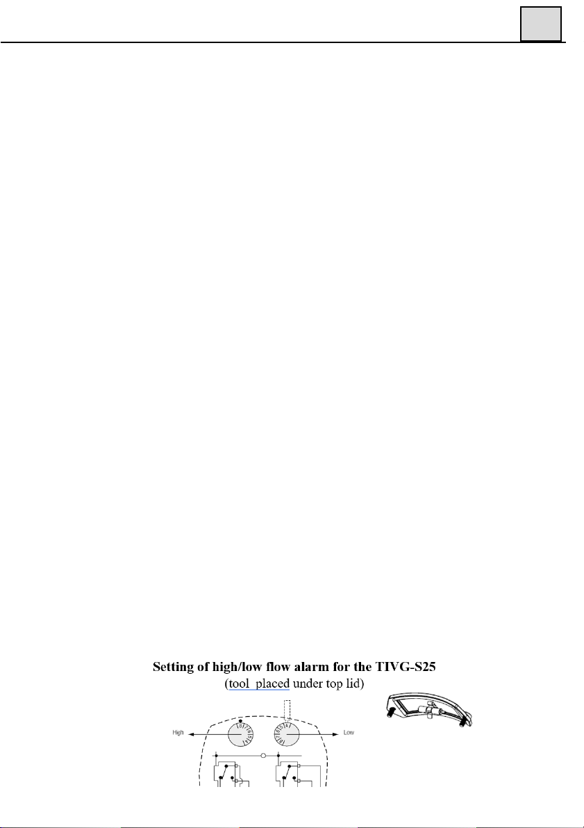
For TIVG-S25: To readjust, remove the two screws that hold the cover at the
top of the blue housing. The two adjusting dials are then visible through the
opening. Underneath the removed cover, you will find a small tool necessary
to use in order to change the adjusting dials position.
The adjusting dials are marked the same as the scale in the front and this mar-
king can be used to approximately find the right switch/alarm point for the ac-
tual application. Put the tool inside the drilled hole on the top of the adjusting
dial and gently move the dial sideways to the desired position. If the two ad-
justing dials are set to the same position, the micro switches will trip at the
same time. If possible, use the left adjusting dial for the high flow alarm (hig-
her end of the scale) and the right for the min. flow alarm (the lower end of the
scale), in order to get the best accuracy. If you use the alarms the other way
around, the spring mechanism inside the diaphragm housing will be affected
with lower accuracy as a result, so please try to avoid that. Repeat the
procedure for the next adjusting dial and then put the tool back in its bracket at
the cover.
Figure 7

14 80A2E22
3
For TIVG-V15: To re-adjust, remove the cover and the adjusting dial is then
visible at the top. Put a screwdriver in the slot of the adjusting dial and gently
turn the dial to the desired position. Your will find that you by doing this are
moving the plate, where the micro switch is mounted mechanically.
Adjusting of high/low flow alarm for TIVG-V15
Adjusting dial
Figure 8
If you have the possibility to check against a flow meter in the system, you
will get the best on site adjustment of the switch point.
Reinstall the cover at the top with the two screws and start up the process
again.
3.4 Change of Flow Direction
Empty the pipe system so that it is un-pressurized and has no flow!
At the time of ordering, you must specify in which direction the Flow Monitor
shall be mounted i.e. from which side is the flow entering the Pipe Section and
how you would like to read the scale. (Please refer to fig. 6 below for alternatives.)
If, for some reason, the Flow Monitor is ordered with the wrong flow direction,
it is possible to change this in the field.
3.4.1 Flow direction Selector
The threaded brass version DN40 and the flanged stainless steel version are
delivered with a flow direction selector that can be used for both directions.
To change the direction, loosen the four (4) hexagon screw, which hold the di-
aphragm housing to the Pipe Section.
1,5
174A2E
15 80A2E22
3
Remove the diaphragm housing and you will see the flow direction selector (it
might have attached itself to the bottom side of the diaphragm housing). Replace
the flow direction selector in the configuration for your system (see fig. 6).
Please also remember to turn the red arrow mounted on the Pipe Section
only available on the brass threaded version G40.
Change of the flow direction on our threaded Stainless Steel Pipe Sections is not
possible in the field without ordering a new Pipe Section and we kindly ask you
to contact your local representative or Eletta Flow AB, Sweden for help.
3.5 Change of Dial Orientation
As the Eletta Flow Monitors are not limited to a certain mounting position in
the piping system, the large visible dial can be mounted in several positions to
suit the application. (please refer to fig. 7). If you need to change the orienta-
tion in the field, please do as follows;
Note! Make sure that all electrical connections are set to power off before
starting the following procedure!
Remove the front glass with the four screws that hold it in place. Push the
pointer towards the dial and then upwards until the round hole in the pointer
matches the spindle coming out from the mechanism and then remove the
pointer. Undo the two screws that hold the dial and turn the dial 90° to the des-
ired position and tighten the screws in the predrilled holes. Reinstall the poin-
ter according to the new orientation with the reverse procedure from when it
was removed.
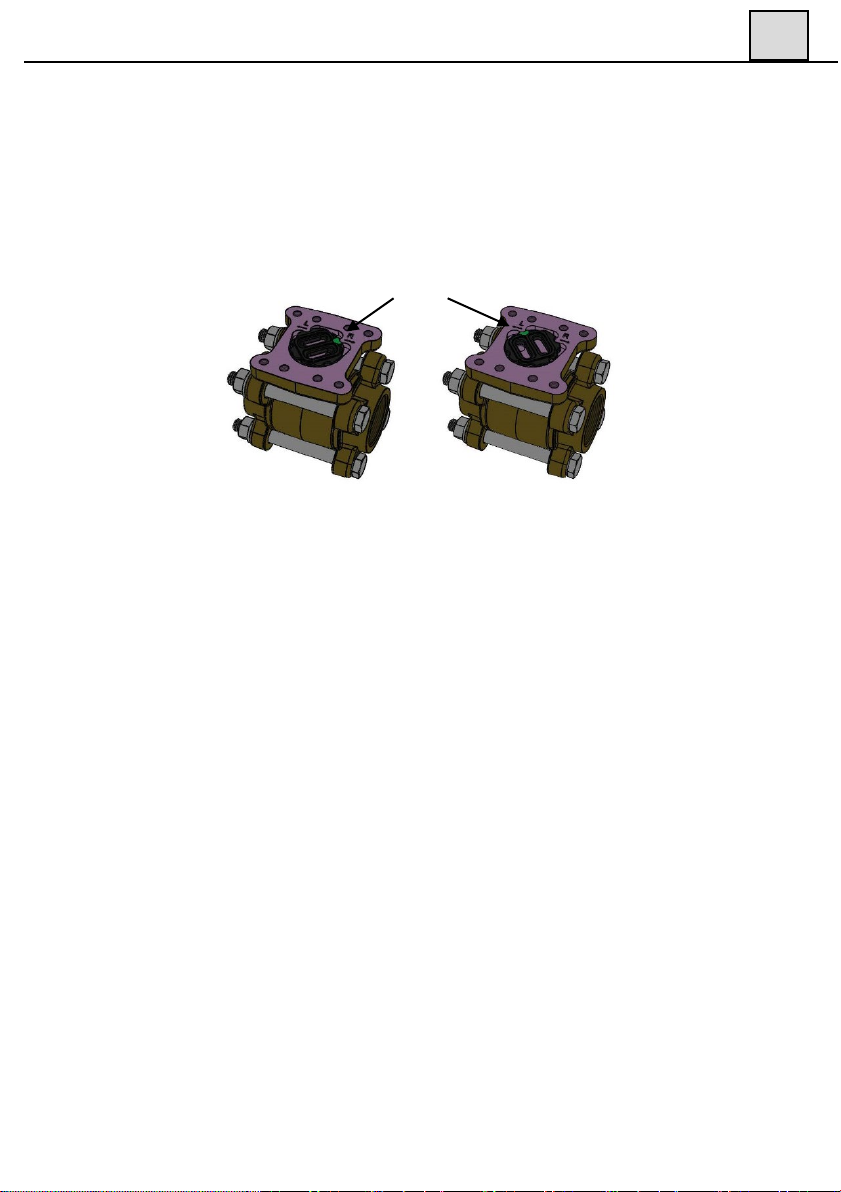
The green dot marks the chosen flow
direction, R for right and L for left.
Figure 9

16 80A2E22
Figure 6
mount
Trouble shooting
4
Dial orientation and ordering code
The spindle and the pointer has a square fitting which make s it possible to in-
stall the pointer in four (4) different positions and make sure that you put it
firmly in the right position for your application. When there is no flow
through the Monitor, the pointer shall point to the beginning of the red part of
the scale = zero position.
Note that a change of the mounting direction of the dial also can make it ne-
cessary to change the flow direction selector (see section 3.4).
4.1 Verification of flow
We would like to stress the fact that all Indicating units on the Eletta Flow
Monitors are calibrated and adjusted individually in water in a specially
purpose built calibrated flow rig in our workshop. This means that we have
calibrated/adjusted the Monitors under reference conditions with enough
straight runs before and after, always the same liquid, temperature, flows and
pressure. If you find our Monitors to show another value compared to a
reference meter on site, it can well be due to the fact that the reference meter
has been calibrated under other reference conditions and that our Monitor
have other conditions on site in the actual application, than we used under the
calibration prior to shipping.
3
Figure 10

17 80A2E22
4
The Monitor is not showing any or the wrong value:
Is the Monitor mounted correctly with respect to the flow direction? Please
check the arrow on the outside of the pipe section with the actual (true) flow
direction For threaded version DN40 and stainless flanged -models, check the
flow direction selector inside the monitor. Make sure that it is corresponding
to the true flow, see 3.4.
Is there any flow in the pipe? And is it enough to create the needed ∆ρ?
Do you have the right orifice plate for the application? Check the stamped
values on the orifice plate. (pipe section model number and flow)
If you are using compression couplings into the Monitor inlet, check that the
inside diameter is enough to avoid the “nozzle” effect described above in
section 2.3 and also check the table for the minimum correct inner diameter in
the same section.
Are there enough straight runs upstream and downstream the Monitor? (10
diameters upstream and 5 downstream.)
Do you have valves or bends in more than one plane within the above straight
runs? If so, move the Monitor further away to achieve enough straight runs.
You can of course verify the flow in the Eletta Flow Monitor versus an- other
flow meter in the system or take the Monitor out and put in a flow test rig, if
you have the possibility.
If the above is not the case there is a need to send the Monitor to the
Distributor or directly to The Eletta Service department for control.
If you find process liquid/gas coming out of the Control Unit;
Most probably you will find a broken lever, the small stainless steel shaft
going through a rubber sealing and it is attached to the diaphragm in the end.
If you have exposed the Monitor to excessive pressure (over 16 bar/232PSI
standard) or if the process liquid/gas is too aggressive to the rubber in the sea-
ling, it can cause the sealing to break.
Please check the identification plate/tag on the Monitor and write down the
serial number, flow range and liquid before ordering a new lever from your re-
presentative or us.
4.2 Electrical connections
Please always see to that you are using the right voltage and current (see sec-
tion 1.2) and that you have connected all the leads in a proper way (see section
2.7). If you open the cover on the Control Unit of the Monitor it is normally

18 80A2E22
4
very easy to see, if a component is broken/burned. If you find the micro swit-
ches are malfunctioning, it is possible to order new ones from Eletta Flow
or your representative and replace them on site.
If you need to order a complete Monitor or a Control Unit for any reason, ple-
ase check the identification plate/tag and write down the serial number, flow
range and liquid and order a new Unit from us. We will ship you the complete
Control Unit with diaphragm housing and you can then easily fit the new
Control Unit to your existing Pipe Section with only four (4) screws, (please
see section 2.5 for details).
4.3 Spares
We are proud to say that our Flow Monitors are well known for their long life-
time and robust construction but inevitably, it is sometimes needed to order
spare parts. We refer to section 7 where you can find an exploded drawing
showing all replaceable components included in the Flow Monitor.
19 80A2E22
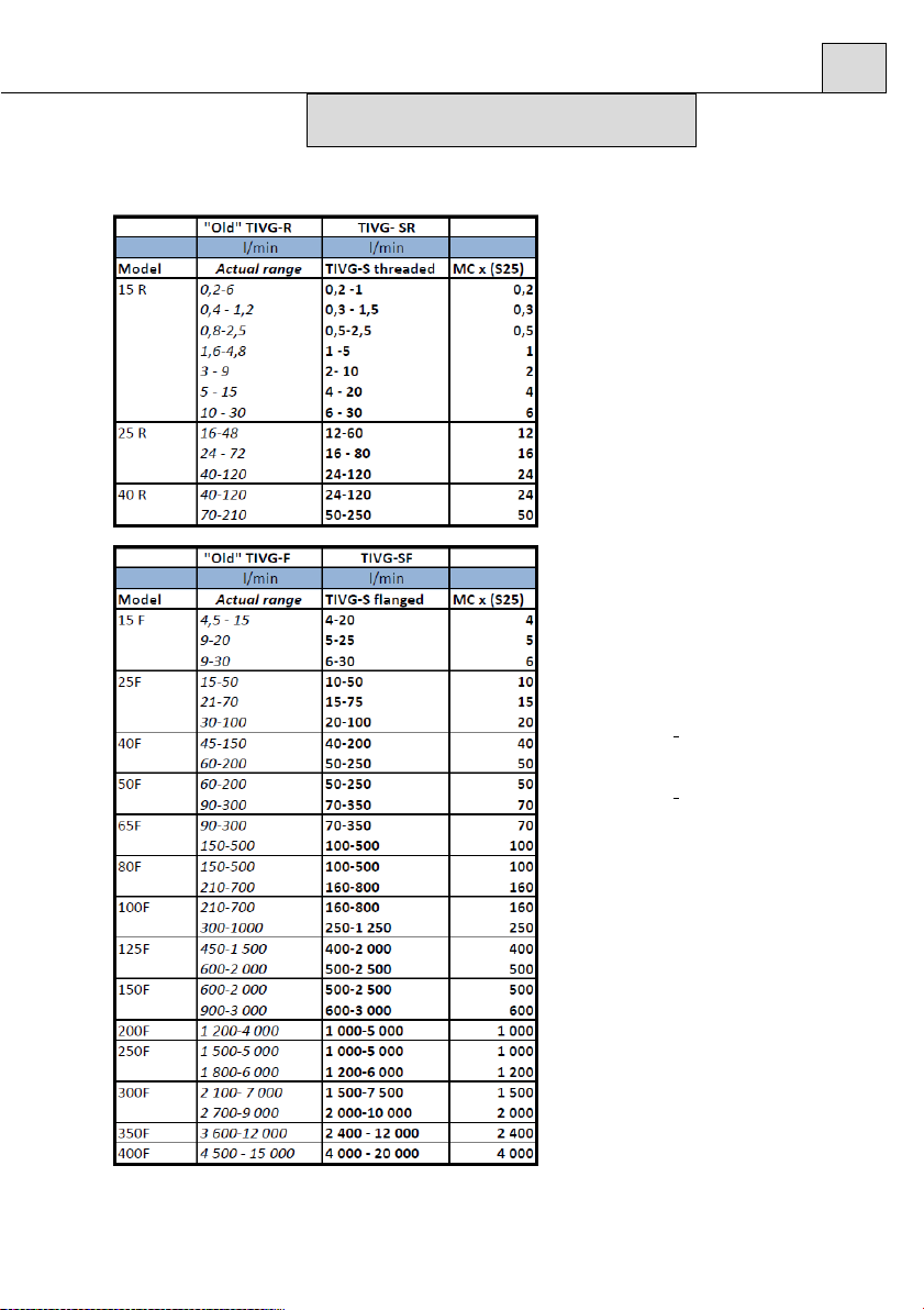
5.1 Measuring Ranges
Tables
5
MC = Measuring constant
on TIVG-S25

20 80A2E22
5
5.2Weight and Dimensions
TIVG-
15 and 25R
TIVG-
V15-40R
This manual suits for next models
25
Table of contents
Other Eletta Measuring Instrument manuals


